3D DISCRETE DISLOCATION DYNAMICS APPLIED TO ... - NUMODIS
3D DISCRETE DISLOCATION DYNAMICS APPLIED TO ... - NUMODIS
3D DISCRETE DISLOCATION DYNAMICS APPLIED TO ... - NUMODIS
You also want an ePaper? Increase the reach of your titles
YUMPU automatically turns print PDFs into web optimized ePapers that Google loves.
2.2 Computation of stresses and displacements of dislocations 15<br />
includes four contributions:<br />
(i) the force due to the internal stress field produced by all the other dislocation segments in the<br />
simulation volume except by two neighboring segments and the considered segment itself<br />
(ii) the force due to applied stress fields<br />
(iii) the force due to the line tension<br />
(iv) the force due to the Peierls stress<br />
The forces due to atomistic-level interactions, such as dragging forces by solute atoms or jogs, are not<br />
treated explicitly. They can be included implicitly, however, by modifying the motion rule which de-<br />
fines the relation between the glide velocity and the effective shear stress of a segment (see Sec. 2.3).<br />
Internal stresses<br />
To compute the internal stresses at the center of a segment, the expression of the stress field of a<br />
single finite straight segment is required. This problem has been addressed by Li ([Li 64]). Li has<br />
found an interesting fact from the stress solution of an angular dislocation made of two semi-infinite<br />
dislocations joined together at one point. According to Li, the stress field of an angular dislocation<br />
is the sum of the stress fields of each dislocation arm, i.e., a semi-infinite dislocation. Although the<br />
stress field of a semi-infinite dislocation does not obey the equations of equilibrium, the sum of the<br />
stress fields of two semi-infinite dislocations satisfies the equilibrium.<br />
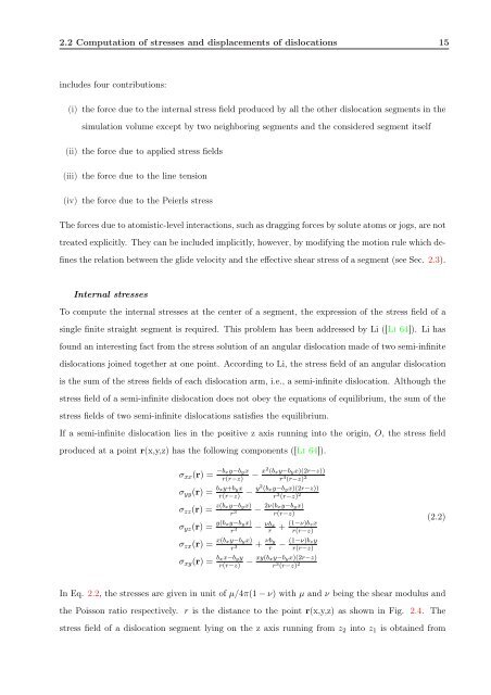
If a semi-infinite dislocation lies in the positive z axis running into the origin, O, the stress field<br />
produced at a point r(x,y,z) has the following components ([Li 64]).<br />
σxx(r) = −bxy−byx<br />
r(r−z) − x2 (bxy−byx)(2r−z))<br />
r 3 (r−z) 2<br />
σyy(r) = bxy+byx<br />
r(r−z) − y2 (bxy−byx)(2r−z))<br />
r 3 (r−z) 2<br />
σzz(r) = z(bxy−byx)<br />
r 3<br />
σyz(r) = y(bxy−byx)<br />
r 3<br />
σzx(r) = x(bxy−byx)<br />
r 3<br />
σxy(r) = bxx−byy<br />
r(r−z)<br />
− 2ν(bxy−byx)<br />
r(r−z)<br />
− νbx<br />
r<br />
+ νby<br />
r<br />
+ (1−ν)bzx<br />
r(r−z)<br />
− (1−ν)bzy<br />
r(r−z)<br />
− xy(bxy−byx)(2r−z)<br />
r 3 (r−z) 2<br />
In Eq. 2.2, the stresses are given in unit of µ/4π(1 − ν) with µ and ν being the shear modulus and<br />
the Poisson ratio respectively. r is the distance to the point r(x,y,z) as shown in Fig. 2.4. The<br />
stress field of a dislocation segment lying on the z axis running from z2 into z1 is obtained from<br />
(2.2)


