Installation and start-up - Stange Energietechnik GmbH
Installation and start-up - Stange Energietechnik GmbH
Installation and start-up - Stange Energietechnik GmbH

You also want an ePaper? Increase the reach of your titles
YUMPU automatically turns print PDFs into web optimized ePapers that Google loves.
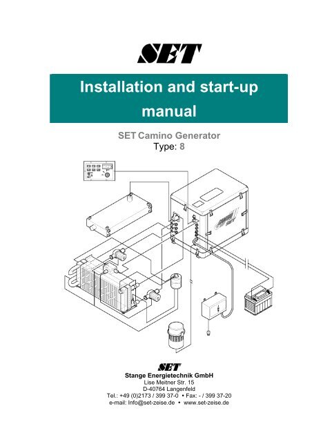
<strong>Installation</strong> <strong>and</strong> <strong>start</strong>-<strong>up</strong><br />
manual<br />
SET Camino Generator<br />
Type: 8<br />
<strong>Stange</strong> <strong>Energietechnik</strong> <strong>GmbH</strong><br />
Lise Meitner Str. 15<br />
D-40764 Langenfeld<br />
Tel.: +49 (0)2173 / 399 37-0 Fax: - / 399 37-20<br />
e-mail: Info@set-zeise.de www.set-zeise.de
Preface<br />
Camino Generator<br />
SET-CAMINO Generator for safe <strong>and</strong> mains-independent power s<strong>up</strong>ply.<br />
The SET-CAMINO Generator is designed for installation in vehicles.<br />
It is particularly suited due to:<br />
• Its ideal construction, workmanship <strong>and</strong> function.<br />
• High safety in operation <strong>and</strong> nearly unlimited service life.<br />
• Low power consumption.<br />
• Compact installation dimensions.<br />
• Excellent sound insulation.<br />
Mains-independent power s<strong>up</strong>ply powerful, small <strong>and</strong> low-noise only by<br />
<strong>Stange</strong> <strong>Energietechnik</strong> <strong>GmbH</strong> with original SET-CAMINO Generators.<br />
.<br />
Have installation <strong>and</strong> mounting carried out only by a specialised workshop authorised<br />
by SET.<br />
Please do not hesitate to contact us for mounting, planning <strong>and</strong> installing the SET-<br />
CAMINO Generator:<br />
<strong>Stange</strong> <strong>Energietechnik</strong> <strong>GmbH</strong><br />
Lise Meitner Str. 15<br />
D-40764 Langenfeld<br />
Tel.: +49 (0)2173 / 399 37-0<br />
Fax: +49 (0)2173 / 399 37-20<br />
e-mail: Info@set-zeise.de<br />
www.set-zeise.de<br />
03-04-01 Introduction 1-2
Table of contents<br />
Camino Generators<br />
1 Introduction......................................................................................................1-5<br />
2 Basic safety notes ...........................................................................................2-6<br />
2.1 Safety provisions....................................................................................................................2-6<br />
2.1.1 Obligations of the owner ...........................................................................................................2-6<br />
2.1.2 Pictograms for safety <strong>and</strong> danger hints.....................................................................................2-7<br />
2.1.3 Principle; application for the purpose intended..........................................................................2-7<br />
2.2 Organisational measures.......................................................................................................2-8<br />
2.3 Basic duties............................................................................................................................2-9<br />
2.4 Safety hints for certain operating phases ..............................................................................2-9<br />
2.4.1 Normal operation.......................................................................................................................2-9<br />
2.4.2 Continuous operation ..............................................................................................................2-10<br />
2.4.3 Special work............................................................................................................................2-10<br />
2.5 Hints for specific types of danger.........................................................................................2-11<br />
2.5.1 Electrical power.......................................................................................................................2-11<br />
2.5.2 Gas, dust, steam, smoke ........................................................................................................2-11<br />
2.6 Notes for warranty <strong>and</strong> liability.............................................................................................2-12<br />
2.6.1 Storing the generator ..............................................................................................................2-12<br />
2.6.2 Claims .....................................................................................................................................2-12<br />
2.6.3 Figures <strong>and</strong> drawings..............................................................................................................2-12<br />
2.6.4 Protected rights .......................................................................................................................2-12<br />
2.6.5 Environmental protection ........................................................................................................2-13<br />
2.6.6 Dangers <strong>and</strong> warning signs.....................................................................................................2-13<br />
3 Preparation for installation ...........................................................................3-14<br />
3.1 Scope of s<strong>up</strong>plies.................................................................................................................3-14<br />
3.2 Protective measures against mechanical risks....................................................................3-15<br />
3.3 Protective measures against electrical risks........................................................................3-15<br />
3.3.1 Electrical risks in the AC circuit 230V 50Hz.............................................................................3-15<br />
3.3.2 Electrical risks in the DC circuit 12V........................................................................................3-15<br />
3.4 Protective measures for the electrical installation ...............................................................3-16<br />
3.4.1 Electrical installation of the AC circuit 230V 50Hz...................................................................3-16<br />
3.4.2 Electrical installation of the DC circuit 12V..............................................................................3-17<br />
3.5 Protective measures for mechanical installation .................................................................3-17<br />
3.6 Fuel system..........................................................................................................................3-18<br />
3.7 Combustion air s<strong>up</strong>ply .........................................................................................................3-18<br />
3.8 Safety notes, summary ........................................................................................................3-19<br />
3.9 Exhaust gas system.............................................................................................................3-20<br />
3.10 Cooler unit............................................................................................................................3-20<br />
4 <strong>Installation</strong> data .............................................................................................4-21<br />
4.1 Technical data......................................................................................................................4-21<br />
4.1.1 Technical data „SET Camino Generator“ ................................................................................4-21<br />
4.1.2 Technical data „drive engine“ ..................................................................................................4-22<br />
4.2 Technical installation data ...................................................................................................4-23<br />
4.2.1 Dimensions – „soundproofing hood“ .......................................................................................4-23<br />
03-04-01 Introduction 1-3
Camino Generator<br />
4.2.2 Dimensions „mounting frame“................................................................................................. 4-24<br />
4.3 Dimensions „cooler unit example“ ....................................................................................... 4-25<br />
4.4 Connections <strong>and</strong> links at the SET Camino Generator ........................................................ 4-26<br />
4.4.1 Electrical <strong>and</strong> control connections .......................................................................................... 4-26<br />
4.4.2 Cooling system connections ................................................................................................... 4-27<br />
4.4.3 Fuel s<strong>up</strong>ply connections ......................................................................................................... 4-28<br />
4.4.4 Exhaust gas system connections ........................................................................................... 4-29<br />
4.4.5 External air filter connection (Option)* .................................................................................... 4-30<br />
5 <strong>Installation</strong> of the SET Camino Generator...................................................5-31<br />
5.1 General................................................................................................................................5-31<br />
5.2 Environment ........................................................................................................................ 5-32<br />
5.3 Foundation........................................................................................................................... 5-33<br />
5.4 <strong>Installation</strong> of the cooling system ........................................................................................ 5-34<br />
5.4.1 Direction of delivery of the coolant.......................................................................................... 5-35<br />
5.4.2 Piping at the cooling circuit „generator“ .................................................................................. 5-36<br />
5.4.3 Piping at the cooling circuit „engine“....................................................................................... 5-37<br />
5.4.4 Piping „expansion vessel“....................................................................................................... 5-38<br />
5.5 <strong>Installation</strong> of external air filter (Option) .............................................................................. 5-39<br />
5.6 <strong>Installation</strong> of the exhaust gas system ................................................................................ 5-40<br />
5.7 <strong>Installation</strong> of the fuel system .............................................................................................. 5-41<br />
5.7.1 <strong>Installation</strong> of the separate fuel s<strong>up</strong>ply system ....................................................................... 5-42<br />
6 Electrical installation.....................................................................................6-44<br />
6.1 <strong>Installation</strong> of control panel.................................................................................................. 6-45<br />
Connection of the electrical fuel delivery pump .......................................................................... 6-47<br />
6.2 Connection of main capacitor <strong>and</strong> main distributor............................................................. 6-48<br />
6.3 Electrical system of the vehicle ........................................................................................... 6-49<br />
6.4 Connection for additional 12 V consumer ........................................................................... 6-50<br />
6.5 Mounting <strong>and</strong> installation of the <strong>start</strong>er battery ................................................................... 6-51<br />
7 Initial <strong>start</strong>-<strong>up</strong>.................................................................................................7-53<br />
7.1 Coolant filling....................................................................................................................... 7-54<br />
7.2 Operation............................................................................................................................. 7-55<br />
7.3 Start-<strong>up</strong>................................................................................................................................7-55<br />
7.3.1 For initial <strong>start</strong> proceed as follows .......................................................................................... 7-57<br />
8 <strong>Installation</strong> documents of sub-s<strong>up</strong>pliers.....................................................8-58<br />
8.1 Sub-s<strong>up</strong>plier documents - General...................................................................................... 8-58<br />
8.2 Sub-s<strong>up</strong>plier documents - Engine ....................................................................................... 8-58<br />
8.3 Sub-s<strong>up</strong>plier documents - Generator .................................................................................. 8-58<br />
8.4 Sub-s<strong>up</strong>plier documents – Electrical/control system........................................................... 8-58<br />
8.5 Sub-s<strong>up</strong>plier documents – Cooling system......................................................................... 8-58<br />
8.6 Sub-s<strong>up</strong>plier documents – Tank system*............................................................................ 8-58<br />
8.7 Sub-s<strong>up</strong>plier documents – External air filter* ...................................................................... 8-58<br />
8.8 Sub-s<strong>up</strong>plier documents – Exhaust gas system ................................................................. 8-58<br />
03-04-01 Introduction 1-4
1 Introduction<br />
Camino Generators<br />
Prior to installing, connecting <strong>and</strong>/or <strong>start</strong>ing, please read this manual which has<br />
been specifically prepared for the SET-CAMINO Generator.<br />
<strong>Installation</strong> can be carefully prepared only when you are acquainted with the installation<br />
<strong>and</strong> <strong>start</strong>-<strong>up</strong> manual. Only in this way it is possible to procure installation accessories<br />
<strong>and</strong> the desired options in due time.<br />
This <strong>Installation</strong> <strong>and</strong> <strong>start</strong>-<strong>up</strong> manual<br />
includes chapters covering the following subjects:<br />
• Basic safety notes<br />
• <strong>Installation</strong> preparation <strong>and</strong> installation data<br />
• <strong>Installation</strong> of the SET Camino Generator<br />
• Electrical installation<br />
• Initial <strong>start</strong>-<strong>up</strong><br />
• <strong>Installation</strong> documents of sub-s<strong>up</strong>pliers<br />
The separate Operating manual with the following chapters should be used by<br />
the operator of the SET-CAMINO Generator...<br />
• How to h<strong>and</strong>le the SET Camino Generator<br />
• Construction <strong>and</strong> functioning<br />
• Activation <strong>and</strong> operation<br />
• Preventive <strong>and</strong> corrective maintenance<br />
• Elimination of failures <strong>and</strong> faults<br />
• Operating <strong>and</strong> maintenance manuals of sub-s<strong>up</strong>pliers<br />
Thus please read the operating manual <strong>and</strong> the installation/<strong>start</strong>-<strong>up</strong> manual<br />
carefully prior to any manipulation. It contains important information, regulations<br />
<strong>and</strong> safety rules.<br />
03-04-01 Introduction 1-5
2 Basic safety notes<br />
2.1 Safety provisions<br />
Camino Generator<br />
No warranty <strong>and</strong> liability claims will be accepted for personal <strong>and</strong> property damage if<br />
due to one or several of the following causes:<br />
− Non-compliance with these particular or other known precautions.<br />
− Failure to operate <strong>and</strong> h<strong>and</strong>le the unit with the necessary care.<br />
2.1.1 Obligations of the owner<br />
The owner shall agree to <strong>start</strong> <strong>up</strong> the generator only after having made himself acquainted<br />
with the safety regulations <strong>and</strong> h<strong>and</strong>ling of the generator.<br />
These are:<br />
− Accident prevention regulations<br />
− General <strong>and</strong> engine/plant related safety notes<br />
− Safeguards of the generator<br />
− Actions in emergency cases<br />
− Operation of the generator<br />
− Activities when <strong>start</strong>ing <strong>up</strong> the generator<br />
− Behaviour in case of failure<br />
− Shutting down the generator<br />
− Transport of the generator<br />
− Disposal of utilities <strong>and</strong> auxiliary materials<br />
The generator shall be installed properly by specialists only.<br />
1. Check the place of installation <strong>and</strong> its environment for suitability.<br />
2. You are obliged to eliminate any danger at the generator <strong>and</strong> its operation.<br />
3. The operating manual must be readily available for the operator at the place of<br />
installation of the generator.<br />
4. Follow the regulations for safe working <strong>and</strong> accident prevention.<br />
5. The operating manual must have been read <strong>and</strong> understood.<br />
6. Follow the actions dealt with in the operating manual.<br />
7. Pictograms in the operating manual are used to underline particularly important<br />
information (for explanations of the pictograms refer to chapter 2.1.2).<br />
03-04-01 Basic safety notes 2-6
Camino Generators<br />
8. The unit shall be operated only with the soundproofing housing closed.<br />
9. With the soundproofing housing open, there is the risk of injury by the belts of<br />
the dynamo.<br />
10. The electrical loading of the generator by connected power consumers must not<br />
exceed that indicated at the nameplate.<br />
2.1.2 Pictograms for safety <strong>and</strong> danger hints<br />
The following pictograms indicate where safety <strong>and</strong> danger hints in this operating<br />
manual must be complied with in particular:<br />
Emphasises dangerous situations with possible personal injury, also<br />
possible generator damage.<br />
Danger due to electrical current. The necessary works shall be carried<br />
out only by specialised electricians.<br />
Notes concerning useful hints, explanations <strong>and</strong> s<strong>up</strong>plements for<br />
h<strong>and</strong>ling the generator.<br />
No Smoking<br />
Fires <strong>and</strong> open light forbade.<br />
2.1.3 Principle; application for the purpose intended<br />
The generator has been built in accordance with the latest state of the art <strong>and</strong> approved<br />
safety rules. The requirements of the generator applicable in the manufacturer’s<br />
country, Germany, (DIN, VDE <strong>and</strong> Machine Protection Act) have been taken<br />
into account. However, improper use may cause danger to the life <strong>and</strong> limb of the<br />
user or third parties as well as damage to the generator <strong>and</strong> other property.<br />
Use the generator only in proper technical condition <strong>and</strong> for the purpose intended as<br />
well as according to safety st<strong>and</strong>ards with due consideration given to potential hazards!<br />
Eliminate any failure immediately which might affect safety (or have them<br />
eliminated).<br />
The SET-CAMINO generator shall be used only for power generation <strong>and</strong> operating<br />
electrical units with coincident voltages.<br />
Application for the purpose intended also includes compliance with<br />
the operating manuals <strong>and</strong> meeting the inspection <strong>and</strong> maintenance<br />
requirements.<br />
03-04-01 Basic safety notes 2-7
2.2 Organisational measures<br />
Camino Generator<br />
Keep the operating manual easily accessible at the place of installation of the generator<br />
(in tool compartment or the box provided for this purpose)!<br />
In addition to the operating manual, follow <strong>and</strong> direct the general legal <strong>and</strong> other<br />
binding regulations for accident prevention <strong>and</strong> environmental protection!<br />
Such duties may also refer, for instance, to the h<strong>and</strong>ling of dangerous materials or<br />
the provision/wearing of personal protective equipment.<br />
The operating manual must have been read <strong>and</strong> understood.<br />
It will be too late during service. This is particularly applicable to persons who work<br />
time <strong>and</strong> again only at the generator, e.g. during setting <strong>up</strong>, maintenance, etc.<br />
Use the personal protective equipment if necessary or required by regulations!<br />
Observe all safety <strong>and</strong> danger notes at the generator!<br />
Keep all safety <strong>and</strong> danger notes at the generator in readable state!<br />
Shut down the generator immediately in case of safety relevant modifications at the<br />
generator or its operating performance. Do not carry out any modification <strong>and</strong>/or attachments<br />
or re-structuring work at the generator unless the prior written approval<br />
by the manufacturer has been obtained. This might affect the safety of the generator!<br />
This is also applicable to the installation <strong>and</strong> setting of safeguards <strong>and</strong> safety<br />
valves as well as for welding work carried out at load-bearing components. Any<br />
structural modification shall be done by the manufacturer only.<br />
Use only original spare parts <strong>and</strong> original accessories of the manufacturer! Spare<br />
parts <strong>and</strong> accessories must meet the technical requirements specified by the manufacturer.<br />
Original components will ensure this.<br />
Replace all hose lines at the intervals indicated <strong>and</strong>/or appropriate, even if no safety<br />
relevant defects can be seen!<br />
Keep the intervals for repeated checks/inspection which are specified or given in the<br />
operating manual!<br />
Appropriate workshop equipment is required to carry out maintenance/repair work.<br />
Inform yourself of special tools!<br />
Observe the fire alarm <strong>and</strong> fire fighting facilities!<br />
Inform other persons of the location <strong>and</strong> operation of fire extinguishers!<br />
03-04-01 Basic safety notes 2-8
2.3 Basic duties<br />
Camino Generators<br />
Work at/by the generator shall be carried out only by reliable personnel. Observe the<br />
legally admissible minimum age!<br />
Work at the electrical equipment of the generator shall be carried out only by specialised<br />
electricians in accordance with the rules of electrical engineering. Work at<br />
electrical s<strong>up</strong>ply installations shall be carried out by authorised specialists only in<br />
compliance with the DIN VDE provisions <strong>and</strong> the regulations of the relevant country.<br />
Check the electrical design of the generator at regular intervals.<br />
2.4 Safety hints for certain operating phases<br />
Follow the specific safety notes during the individual phases of operation.<br />
2.4.1 Normal operation<br />
Refrain from any activity which might affect safety!<br />
Arrange for the necessary precautions so that the generator is operated only in safe<br />
<strong>and</strong> properly functioning state!<br />
Operate the generator only with all safeguards <strong>and</strong> safety devices, e.g. removable<br />
safeguards, emergency OFF devices, sound insulation, exhaustion systems,<br />
mounted <strong>and</strong> functioning properly!<br />
Check the generator for visible damage <strong>and</strong> defects once a day! Eliminate changes,<br />
if any (including the operating performance) immediately, shut down <strong>and</strong> secure the<br />
generator, if necessary!<br />
In case of functional failures, shut down <strong>and</strong> secure the generator immediately!<br />
Eliminate failure immediately (or have them eliminated)!<br />
Observe the switching on/off processes, control display in accordance with the operating<br />
manual!<br />
Prior to switching on/<strong>start</strong>ing the generator, make sure that no person is at risk due<br />
to the <strong>start</strong>ing generator!<br />
Do not switch off <strong>and</strong>/or remove exhaustions <strong>and</strong> bleeding units with the generator<br />
running.<br />
03-04-01 Basic safety notes 2-9
2.4.2 Continuous operation<br />
Camino Generator<br />
Note <strong>and</strong> follow the national working, operating <strong>and</strong> safety regulations for safely<br />
h<strong>and</strong>ling this generator <strong>and</strong> its trouble-free operation.<br />
Check the generator for visible damage at regular intervals!<br />
The generator <strong>and</strong> the control system shall be operated only by instructed operators!<br />
The parameters set by the manufacturer are st<strong>and</strong>ard setting values!<br />
Follow all hints given for the case of malfunction (refer also to the chapter „Failure,<br />
elimination of failure, repair“). If the actions mentioned there do not result in the<br />
elimination of failure, please contact the SET after-sales service department!<br />
Tel.: +49 (0)2173 / 399 37-0 Fax: - / 399 37-21<br />
e-mail: service@set-zeise.de www.set-zeise.de<br />
2.4.3 Special work<br />
• Carry out all maintenance <strong>and</strong> installation work at the generator according to the<br />
hints. Shut down the generator properly.<br />
• Any person in the facility of the owner who is authorised to carry out assembly,<br />
<strong>start</strong>-<strong>up</strong>, operation, maintenance, repair or other work, shall have read <strong>and</strong> understood<br />
the operating manual, <strong>and</strong> in particular the safety notes.<br />
• Keep all setting, maintenance <strong>and</strong> inspection work <strong>and</strong> dates specified in the operating<br />
manual, including the data concerning the replacement of components/sub-assemblies!<br />
This work shall be carried out only by specialised personnel.<br />
• Observe all switching on/off processes according to the operating manual <strong>and</strong><br />
the hints for maintenance for any work related to the operation, production adaptation,<br />
re-equipment or setting of the generator <strong>and</strong> its safety relevant equipment<br />
as well as inspection, maintenance <strong>and</strong> repair!<br />
• Switch off <strong>and</strong> secure the generator against unintended re-connection when carrying<br />
out maintenance work!<br />
• Lock the main comm<strong>and</strong> facilities, withdraw the key <strong>and</strong> keep it!<br />
• Attach a warning plate at the main switch!<br />
03-04-01 Basic safety notes 2-10
2.5 Hints for specific types of danger<br />
2.5.1 Electrical power<br />
Camino Generators<br />
• Use only original fuses with the amperage specified! Switch off the generator<br />
immediately in case of power failure!<br />
• Work at electrical installations or operating means shall be carried out only by<br />
specialised electricians in accordance with the rules of electrical engineering.<br />
• Disconnect all engine <strong>and</strong> plant parts at which inspection, maintenance or repair<br />
work shall be carried out, from the voltage s<strong>up</strong>ply. Check the disconnected components<br />
for their proper isolation prior to <strong>start</strong> any work!<br />
• Check/inspect the electrical equipment of the generator at regular intervals.<br />
Eliminate defects, such as loose connections <strong>and</strong>/or burnt cables immediately.<br />
• If work shall be carried out at live components, employ a second person who can<br />
activate the emergency off <strong>and</strong>/or main switch with voltage release in case of<br />
emergency. Use voltage-insulated tools only!<br />
For work at high-voltage sub-assemblies, connect the s<strong>up</strong>ply cable to ground <strong>and</strong><br />
short-circuit the components, e.g. capacitors, with the earthing rod after having disconnected<br />
the voltage!<br />
Check the electrical design of the generator at regular intervals.<br />
2.5.2 Gas, dust, steam, smoke<br />
• Carry out welding, burning <strong>and</strong> grinding work at the generator only after having<br />
obtained the specific permission. There may be fire <strong>and</strong> explosion danger!<br />
• Prior to carry out welding, burning <strong>and</strong> grinding work, clean the generator <strong>and</strong> its<br />
environment from dust <strong>and</strong> inflammable materials <strong>and</strong> arrange for sufficient ventilation<br />
(danger of explosion)!<br />
• Observe the national regulations, if any, for work in narrow spaces!<br />
• Follow the safety regulations applicable to the product when h<strong>and</strong>ling oils,<br />
greases <strong>and</strong> other chemical substances!<br />
• Be careful when h<strong>and</strong>ling hot utilities <strong>and</strong> auxiliary materials (danger of burns<br />
<strong>and</strong>/or scalding)!<br />
03-04-01 Basic safety notes 2-11
2.6 Notes for warranty <strong>and</strong> liability<br />
Camino Generator<br />
• Have repair <strong>and</strong> maintenance work carried out by a specialised workshop approved<br />
by SET.<br />
• SET will not accept responsibility <strong>and</strong> liability for work carried out by third party’s<br />
personnel.<br />
• The „General Terms <strong>and</strong> Conditions of Sale <strong>and</strong> S<strong>up</strong>ply“ of SET shall be applicable<br />
in any case. They will be provided to the owner when signing the contract at<br />
the latest.<br />
Warranty <strong>and</strong> liability claims for personal <strong>and</strong> property damage shall be excluded if<br />
due to one or several of the following causes:<br />
• Use of the generator for purposes other than the intended.<br />
• Improper assembly, <strong>start</strong>-<strong>up</strong>, operation <strong>and</strong> maintenance of the generator.<br />
• Operating the generator with defects.<br />
• Non-compliance with the notes in the operating manual concerning transport,<br />
storage, assembly, <strong>start</strong>-<strong>up</strong> <strong>and</strong> maintenance.<br />
• Unauthorised structural modification to the generator.<br />
• Poor monitoring plant components which are subject to wear.<br />
• Improperly carried out repair work, use of third party’s components.<br />
• Catastrophes due to the effects of foreign bodies <strong>and</strong> Force Majeure.<br />
2.6.1 Storing the generator<br />
No warranty claims will be accepted by SET <strong>GmbH</strong> for corrosion damage <strong>and</strong> frost<br />
damage due to improper storage, such as moist rooms or the like.<br />
2.6.2 Claims<br />
No replacement or warranty claims will be accepted for improper transport. In case<br />
of doubt, contact the manufacturer prior to transport.<br />
2.6.3 Figures <strong>and</strong> drawings<br />
Are used for general illustration <strong>and</strong> shall not be decisive for the construction of individual<br />
components. The dimensions specified shall not be binding.<br />
2.6.4 Protected rights<br />
Any right in drawings <strong>and</strong> other documents as well as any disposal right such as<br />
copy <strong>and</strong> disclosure rights shall remain with SET <strong>GmbH</strong>, even in case of the application<br />
of protected rights.<br />
03-04-01 Basic safety notes 2-12
2.6.5 Environmental protection<br />
Camino Generators<br />
• Dispose used materials <strong>and</strong> substances according to the applicable regulations.<br />
Disposal of materials in accordance with environmental st<strong>and</strong>ards will promote<br />
the re-use of valuable materials.<br />
2.6.6 Dangers <strong>and</strong> warning signs<br />
The dangerous areas of the generator are identified by warning plates. These signs<br />
contain information which will protect you from dangers to health, fatal injuries or<br />
property damage!<br />
• Read the appropriate text <strong>and</strong> follow it during work at any case!<br />
• The danger <strong>and</strong> warning signs shall be properly recognised <strong>and</strong> read by the operator!<br />
• Do not remove the plates <strong>and</strong> signs!<br />
We wish you success <strong>and</strong> joy with your<br />
SET-CAMINO Generator!<br />
03-04-01 Basic safety notes 2-13
3 Preparation for installation<br />
3.1 Scope of s<strong>up</strong>plies<br />
Camino Generator<br />
The SET Camino Generator has been packed cleanly after the final inspection by<br />
out quality assurance department. The generator is transported on a wooden pallet.<br />
All components are securely mounted at the pallet. When unpacking, please check<br />
the generator for damage due to transport. In case of damage, if any, please inform<br />
the forwarding agency immediately.<br />
In detail:<br />
CAMINO generator consisting of:<br />
• Capacitor box<br />
• Cooling unit complete<br />
• Exhaust gas silencer<br />
• Control panel for installation<br />
• Control cable with plug<br />
• Operating manual SET<br />
• Engine manual Kubota<br />
03-04-01 Preparation for installation 3-14
3.2 Protective measures against mechanical risks<br />
Camino Generators<br />
The unit is suspended freely oscillating. Vibration absorbers between the soundproofing<br />
housing <strong>and</strong> the assembly frame as well as inside the soundproofing housing<br />
ensure low-vibration operation.<br />
All components required to operate the SET Camino Generator are screwed to the<br />
unit.<br />
Bushings in the housing of the soundproofing housing allow installation of the s<strong>up</strong>ply<br />
connection <strong>and</strong> the outgoing cables without risk.<br />
The sound insulation material used is self-extinguishing in accordance with DIN 752<br />
000.<br />
The generator is designed so that it withst<strong>and</strong>s all loads if used for the purpose intended.<br />
Properly connect the assembly frame with the vehicle body at the points provided for<br />
this purpose.<br />
3.3 Protective measures against electrical risks<br />
Electrical safety has top priority <strong>and</strong> is achieved by various protective measures.<br />
3.3.1 Electrical risks in the AC circuit 230V 50Hz<br />
Type of protection IP54 of the generator ensures complete protection against contact<br />
with live components <strong>and</strong> against damaging dust deposits <strong>and</strong> splash water.<br />
Insulation class „F“ of the winding of the generator is characterised by a high temperature<br />
<strong>and</strong> high short-circuit resistance.<br />
The generator is interference s<strong>up</strong>pressed according to VDE 0875 interference level<br />
N.<br />
All metal parts of the generator are connected to earth.<br />
3.3.2 Electrical risks in the DC circuit 12V<br />
The electrical installation of the generator is of the 2-pole type.<br />
Installed fused in the control module (electronic box)<br />
Fuses: 1 x 15 A, 1 x 3 A, 1 x 5 A.<br />
Plug connectors are completely insulated, the plug for the control line is torsionallysafe<br />
<strong>and</strong> thus also safe against pole changes.<br />
A sophisticated smart electronic generator Diesel monitoring system protects the<br />
generator’s system against damage <strong>and</strong> mal-operation.<br />
03-04-01 Preparation for installation 3-15
Camino Generator<br />
3.4 Protective measures for the electrical installation<br />
The electrical system shall be installed by specialised electricians<br />
only.<br />
3.4.1 Electrical installation of the AC circuit 230V 50Hz<br />
The distribution pox for electrical power – to be mounted by the customer – shall be<br />
at least of IP 54 type of protection.<br />
Install a 2-pole change-over switch with the positions 1 – 0 – 2 as mains/generator<br />
switch.<br />
Install miniature circuit breakers per consumer circuit to protect the consumer circuits.<br />
Lead the electronic connection lines through the appropriate screwed conduit entries.<br />
When replacing a connection line tighten the screwed joints firmly<br />
<strong>and</strong> check for tension.<br />
• Install a protective conductor when installing the electrical system.<br />
• Direct earthing of the generator with the vehicle body is required here.<br />
• In accordance with the regulations of the manufacturer’s country, the protective<br />
measure fault current protective circuit (FI residual current circuit breaker) is required.<br />
Residual current circuit breaker: 0.03A<br />
Another protective measure can be prescribed for installations in other countries.<br />
The installation company for the plant shall be liable in case of accidents if these<br />
regulations are not complied with.<br />
03-04-01 Preparation for installation 3-16
3.4.2 Electrical installation of the DC circuit 12V<br />
Camino Generators<br />
1. Do not connect the pole terminals to the battery unless the installation is completed,<br />
the Diesel engine is ready for operation <strong>and</strong> the <strong>start</strong> switch is in OFF<br />
position<br />
2. Check pole terminals for tight seat.<br />
3. Apply anti-acid grease to the pole heads <strong>and</strong> pole terminals.<br />
4. All control lines are switched in a water-proof plug connector.<br />
5. Electrical installation is minimised.<br />
6. A 3 A line fuse is installed in the terminal box for the use of the electrical fuel delivery<br />
pump beside the SET Camino Generator.<br />
7. The connection cables for the <strong>start</strong>er battery are lead out of the soundproofing<br />
hood, the connection cables are marked (+) <strong>and</strong> (-) <strong>and</strong> are provided with pole<br />
terminals with the same identification (+) <strong>and</strong> (-)<br />
The line cross-section of the connection cables lead out of the sound<br />
protected hood is designed for the erection of the <strong>start</strong>er battery in<br />
the immediate vicinity of the generator.<br />
3.5 Protective measures for mechanical installation<br />
The electrical system shall be installed by a specialised electrician<br />
only. No warranty claims will be accepted in case of improper installation.<br />
03-04-01 Preparation for installation 3-17
3.6 Fuel system<br />
Camino Generator<br />
If an external Diesel tank is to be installed, use design-approved tanks only. Select a<br />
suitably large tank because the fuel is used to cool the nozzles<br />
When using a common Diesel fuel tank with the main engine, install a suitable footoperated<br />
valve <strong>and</strong> a ball valve at the tank connection.<br />
All components, pipings <strong>and</strong> connections must be suitable for Diesel<br />
fuel. Install the fuel lines made of fire-resistant tubing with steel<br />
thread sheathing according to fire prevention st<strong>and</strong>ards.<br />
Permanently installed lines may also consist of copper pipe.<br />
Under certain circumstances it will be necessary to install a primary fuel filter at the<br />
water separator.<br />
The electrical fuel delivery pump used must be suitable for Diesel fuel.<br />
The s<strong>up</strong>ply <strong>and</strong> return lines in the tank must reach the tank bottom.<br />
3.7 Combustion air s<strong>up</strong>ply<br />
• Combustion air is taken in through the opening in the soundproofing hood directly<br />
from the engine room.<br />
• If the temperature of the ambient air in the engine room exceeds 20 °C, s<strong>up</strong>ply<br />
fresh air from outside.<br />
• S<strong>up</strong>ply fresh air through a 40 mm diameter hose. The length of the hose must not<br />
exceed 3 m.<br />
• Mount the external air filter, if required.<br />
• Mount an external air filter* in case of excessive air pollution.<br />
* Option (refer to SET range of accessories)<br />
03-04-01 Preparation for installation 3-18
3.8 Safety notes, summary<br />
Camino Generators<br />
8. Check <strong>and</strong> maintain the <strong>start</strong>er battery after a longer interr<strong>up</strong>tion of operation.<br />
9. Prior to <strong>start</strong>ing the generator, check all connections for tight seat <strong>and</strong> proper<br />
condition.<br />
Increased risk of fire due to leaking fuel.<br />
Malfunction in the system may occur due to failure of the engine cooling or generator<br />
cooling system.<br />
• Operate the generator only with the soundproofing hood closed.<br />
Increased risk of injury due to rotating engine components.<br />
• The air inlet opening in the soundproofing hood must be open so that the combustion<br />
air can flow in easily.<br />
• Carry out maintenance <strong>and</strong> inspection work in accordance with the specification<br />
of this manual.<br />
• Use original <strong>and</strong> identical SET spare parts only for repair work.<br />
• Work at the electrical installation shall be carried out only by specialised electricians<br />
with due consideration given to the applicable regulations.<br />
• Do not <strong>start</strong> the generator without properly functioning cooling water system.<br />
Fuel must not contact the hot surfaces of the generator. Risk of fire!<br />
No Smoking<br />
Fires <strong>and</strong> open light forbade.<br />
03-04-01 Preparation for installation 3-19
3.9 Exhaust gas system<br />
Camino Generator<br />
• All components of the exhaust system used must be of heat-resistant material<br />
<strong>and</strong> installed according to fire prevention st<strong>and</strong>ards.<br />
Use original SET installation parts only.<br />
• The required dimensions must be kept<br />
3.10 Cooler unit<br />
• Suction-proof hose only shall be used.<br />
• The required dimensions must be kept.<br />
• Check the coolant at the expansion vessel at regular intervals.<br />
• The cooling air inlet must have at least the 1.2fold of the area of the cooler.<br />
• The cooling air outlet (free outlet) must have at least the area of the cooler.<br />
Please ensure to increase the cooler air outlet area when using louvres.<br />
03-04-01 Preparation for installation 3-20
4 <strong>Installation</strong> data<br />
4.1 Technical data<br />
4.1.1 Technical data „SET Camino Generator“<br />
CAMINO 8<br />
Manufacturer SET<br />
Output (...kW; cos.phi 1*) 5,5 kW<br />
Voltage (...V ± 6%) 230V<br />
Amperage (single-phase operation) 25 A<br />
Battery charge 14 V - 11 A<br />
Coolant filling<br />
(water with anti-freezing agent)<br />
Cooling water required<br />
(for direct cooling)<br />
8 l<br />
20 l / min<br />
Type of protection IP 54<br />
Insulation class "F"<br />
Frequency<br />
50 Hz<br />
+/- 3 %<br />
CAMINO 8<br />
Manufacturer SET<br />
Output (...kW; cos.phi 1*) 5,5 kW<br />
Voltage (...V ± 6%) 230V<br />
Amperage (single-phase operation) 12.8 / 35 A<br />
Battery charge 14 V - 20 A<br />
Coolant filling<br />
(water with anti-freezing agent)<br />
Cooling water required<br />
(for direct cooling)<br />
8 l<br />
20 l /min<br />
Type of protection IP 54<br />
Insulation class "F"<br />
Frequency 50 Hz +/- 3%<br />
Sound level ... dB(A) 54<br />
Camino Generators<br />
• The full output can be achieved only after a running in phase of approx. 50 hours<br />
of operation.<br />
• The short-circuit proof, self-exciting revolving-field generator can be overloaded<br />
to 10 % for a short period of time.<br />
• For three-phase generators, load unbalance <strong>up</strong> to 80 % is possible.<br />
03-04-01 <strong>Installation</strong> data 4-21
4.1.2 Technical data „drive engine“<br />
CAMINO 8<br />
Drive engine Kubota<br />
Cooling (water with anti-freezing<br />
agent)<br />
Water<br />
Bore 67 mm<br />
Stroke 68 mm<br />
Displacement 497 cm³<br />
Rated speed 3000 min -1<br />
Engine output acc. to DIN 6270 9.32 kW<br />
Combustion air required 0.92 m³/min<br />
Exhaust gas volume 1.29 m³/min<br />
Max. exhaust gas counter-pressure<br />
(H2O)<br />
1200 mm<br />
Fuel consumption 280 g/kWh<br />
Luboil filling SAE 10 - 40 2,5 litres<br />
Coolant filling<br />
(water with anti-freezing agent)<br />
Cooling water required<br />
(for direct cooling)<br />
8 litres<br />
20 l/min<br />
Thermostat 80 °C<br />
Max. admissible inclined position of<br />
engine<br />
Permanent<br />
25 °<br />
short-time<br />
35 °<br />
Camino Generator<br />
• The dynamo s<strong>up</strong>plies 14 V DC to charge the <strong>start</strong>er battery; load unbalance <strong>up</strong> to<br />
80 % is possible.<br />
03-04-01 <strong>Installation</strong> data 4-22
•<br />
4.2 Technical installation data<br />
4.2.1 Dimensions – „soundproofing hood“<br />
Camino Generators<br />
Designation CAMINO 8<br />
1. Output class 5,5 kW<br />
2.<br />
<strong>Installation</strong> position:<br />
(inclination in any direction)<br />
± 25 degrees<br />
3. Weight 210 kg<br />
4. Length (L....mm) 650<br />
5. Total length incl. connections (....mm) 725<br />
6. Width (B....mm) 500<br />
7. Height (H....mm) 593<br />
Deviations possible!<br />
Please note also the dimensional sheets in the Annex.<br />
03-04-01 <strong>Installation</strong> data 4-23
4.2.2 Dimensions „mounting frame“<br />
320<br />
Camino Generator<br />
Designation CAMINO 10<br />
1. Output class 5,5 kW<br />
2. Length (L....mm) 670<br />
3. Distance of bores (a....mm) 650<br />
4. Width (B....mm) 370<br />
Deviations possible!<br />
Please note also the dimensional sheets in the Annex.<br />
03-04-01 <strong>Installation</strong> data 4-24
4.3 Dimensions „cooler unit example“<br />
Camino Generators<br />
The SET cooler unit .......... is described as an example for several possible cooler<br />
versions*. * (refer also to SET range) Other cooler units* can be delivered depending on the order,<br />
conditions <strong>and</strong> application.<br />
Designation CAMINO 8<br />
1. Output class 5,5 kW<br />
2. Length (L....mm) 675<br />
3. Height (H....mm) 383<br />
4. Depth (T....mm) 230<br />
Deviations possible!<br />
Please note also the dimensional sheets in the Annex.<br />
03-04-01 <strong>Installation</strong> data 4-25
Camino Generator<br />
4.4 Connections <strong>and</strong> links at the SET Camino Generator<br />
4.4.1 Electrical <strong>and</strong> control connections<br />
from to Type / size<br />
1. Engine <strong>start</strong>er Starter battery (+) Pole cable/1.0 m long<br />
2. Engine ground Starter battery (-) Pole cable/0.8 m long<br />
3. Electronic box Control panel S<strong>up</strong>plied 5 m cable<br />
4. Electronic box Cooler control system S<strong>up</strong>plied 2 m cable<br />
5.<br />
6.<br />
Generator with fixed capacitor<br />
Generator<br />
power connection<br />
Residual current circuitbreaker/fuses/external<br />
consumers 230V /<br />
External consumers<br />
14V/2 x 3A<br />
Do not disconnect. Danger to<br />
life!!<br />
Wired at the manufacturer’s/s<strong>up</strong>plied<br />
2.0 m power<br />
cable<br />
S<strong>up</strong>plied 0.5 m cable<br />
03-04-01 <strong>Installation</strong> data 4-26
4.4.2 Cooling system connections<br />
Camino Generators<br />
From to Type / size<br />
1. Engine coolant pump Cooler (s<strong>up</strong>ply line)<br />
2. Engine block Cooler (return line)<br />
3. Generator block Cooler (s<strong>up</strong>ply line)<br />
4.<br />
Generator <strong>and</strong> cooled exhaust<br />
gas manifold<br />
Cooler (return line)<br />
Coolant hose<br />
Ø 18 x * long<br />
Coolant hose<br />
Ø 18 x * long<br />
Coolant hose<br />
Ø 15 x * long<br />
Coolant hose<br />
Ø 15 x * long<br />
5. Electronic box Cooler control system S<strong>up</strong>plied 2 m cable<br />
* Length optional<br />
03-04-01 <strong>Installation</strong> data 4-27
4.4.3 Fuel s<strong>up</strong>ply connections<br />
Camino Generator<br />
from to Type / size<br />
1. Engine fuel s<strong>up</strong>ply line Filter / tank S<strong>up</strong>ply line / 0.2m lg.<br />
2. Engine fuel return line Filter / tank S<strong>up</strong>ply line / 0.2m lg.<br />
03-04-01 <strong>Installation</strong> data 4-28<br />
1<br />
2
4.4.4 Exhaust gas system connections<br />
Camino Generators<br />
From to Type / size<br />
Engine exhaust gas elbow (1) Exhaust gas silencer (2)<br />
Flexible exhaust gas line<br />
Ø ...x ...long<br />
For the dimensions of the exhaust gas silencer please refer to the dimensional<br />
sheet in the Annexes.<br />
Inlet <strong>and</strong> outlet of the SET exhaust gas silencer (2) can be changed.<br />
03-04-01 <strong>Installation</strong> data 4-29
4.4.5 External air filter connection (Option)*<br />
Camino Generator<br />
from to Type / size<br />
Connection (1)<br />
(air connection at housing)<br />
* (if any)<br />
External air filter* (2)<br />
Air hose line (3)<br />
Ø 40 x max. 3 m long<br />
03-04-01 <strong>Installation</strong> data 4-30
5 <strong>Installation</strong> of the SET Camino Generator<br />
5.1 General<br />
Camino Generators<br />
This chapter cannot include all possible versions of installation. It deals with the<br />
mounting <strong>and</strong> installation hints (for the application of the SET Camino Generator<br />
according to the purpose intended) for qualified/authorised specialists.<br />
− In case of doubt, in particular if product specific detail information or accessories<br />
to be installed are missing, obtain the relevant information from the specialised<br />
workshop authorised by SET or directly from the manufacturer SET.<br />
− To do so, please always indicate the type designation <strong>and</strong> production number of<br />
the generator (refer also to registration sheet).<br />
After installation, carry out a check for proper functioning. Make sure<br />
that there are no obvious safety defects <strong>and</strong> risks for the user or environment.<br />
The electrical installation shall be <strong>start</strong>ed <strong>up</strong> only by specialised electricians.<br />
− Have the installation work carried out by a specialised workshop authorised by<br />
SET.<br />
− No responsibility <strong>and</strong> liability will be assumed by SET for any work carried out by<br />
third parties<br />
− Use only admitted <strong>and</strong> proper materials for mounting <strong>and</strong> installation.<br />
− It is often the case that later failures are the result of improper installation of the<br />
SET Camino Generator <strong>and</strong> the use of inferior materials<br />
03-04-01 <strong>Installation</strong> of the SET Camino Generator 5-31
5.2 Environment<br />
Camino Generator<br />
1. The place of installation for the SET-CAMINO Generator shall provide sufficient<br />
space so that all maintenance points are readily accessible.<br />
2. The ambient temperature at the place of installation or in the room should not<br />
exceed 20 °C.<br />
3. Higher ambient temperature will reduce the output of the Diesel engine. If the<br />
room temperature exceeds 20 °C, provide for a separate combustion air s<strong>up</strong>ply.<br />
The soundproofing hood of the SET-CAMINO Generator is provided with a<br />
socket where the combustion air must be s<strong>up</strong>plied via the external air filter.<br />
4. At a length of approx. 3 m of the s<strong>up</strong>ply line, a diameter 40 mm venting hose<br />
can be used.<br />
Insulation<br />
The venting hose shall be mechanically resistant <strong>and</strong> installed without<br />
bends, if possible.<br />
The SET-CAMINO Generator is installed in a soundproofing hood <strong>and</strong> does not require<br />
any additional insulation at the place of installation.<br />
When positioning the generator make sure that maintenance work<br />
<strong>and</strong> checks can be carried out without hindrance.<br />
Please test the following after positioning:<br />
− Air filter replacement<br />
− Fuel filter replacement<br />
− Oil filter replacement<br />
− Vee belt replacement<br />
− Coolant bleeding<br />
− Fuse replacement<br />
− Oil check<br />
03-04-01 <strong>Installation</strong> of the SET Camino Generator 5-32
5.3 Foundation<br />
Camino Generators<br />
A solid foundation is required in order to transmit the forces generated by the SET<br />
Camino Generator to as large an area as possible.<br />
Advantageous foundations <strong>and</strong> suitable points of the vehicle bottom are the following:<br />
− solid steel plate (approx. 10 mm)<br />
− glued wooden plate<br />
− Screen printing plate min. 30 mm<br />
Avoid cavities below the foundation.<br />
Carefully screw the foundation to the base area.<br />
The generator has been s<strong>up</strong>plied with a machine frame at which vibration<br />
metal elements are mounted. The vibration metal elements<br />
prevent solid borne noise from transmission onto the vehicle.<br />
Dimensions of machine frame:*<br />
* (refer also to dimensional sheet <strong>and</strong> technical data)<br />
03-04-01 <strong>Installation</strong> of the SET Camino Generator 5-33
5.4 <strong>Installation</strong> of the cooling system<br />
Camino Generator<br />
Install <strong>and</strong> mount hoses with a sufficiently large radius. Select the<br />
place of installation so that sufficient cooling air can flow through.<br />
The complete cooler unit is pre-assembled.<br />
• The maximum distance between the generator <strong>and</strong> the cooler unit should not exceed<br />
5 m!<br />
• Height difference max. 3 m above <strong>and</strong> below the generator.<br />
Components <strong>and</strong> materials:<br />
1. Cooler unit<br />
2. Cooler hose Ø 18 with<br />
hose clips Ø 15-20<br />
3. Cooler hose Ø 115 with<br />
hose clips Ø 15 -20<br />
4. expansion vessel<br />
Use only pressure <strong>and</strong> suction resistant hoses for temperature <strong>up</strong> to<br />
100 °C, refer also to SET accessories.<br />
Make sure that the axial ventilator in the cooler unit is s<strong>up</strong>plied with<br />
sufficient fresh air. Insufficient cooling may result in cooling problems<br />
due to which the engine may switch off due to over-heating.<br />
• Exhaust air opening = cooler size*.<br />
• The fresh air opening for the axial ventilator shall have at least the 1.2fold area of<br />
the exhaust air opening.<br />
• If the exhaust air <strong>and</strong> fresh air openings are lines (e.g. louvres), make sure that<br />
the cooling air can flow in/out without hindrance, increase the exhaust air opening,<br />
if necessary.<br />
* (refer also to dimensional sheet <strong>and</strong> technical data)<br />
03-04-01 <strong>Installation</strong> of the SET Camino Generator 5-34
5.4.1 Direction of delivery of the coolant<br />
Camino Generators<br />
From via to<br />
• Generator cooler s<strong>up</strong>ply line Hose 15mm Generator s<strong>up</strong>ply line<br />
• Generator return line Hose 15mm Generator cooler return line<br />
• Engine cooler return line Hose 18mm Engine s<strong>up</strong>ply line<br />
• Engine return line Hose 18mm Engine cooler return line<br />
03-04-01 <strong>Installation</strong> of the SET Camino Generator 5-35
5.4.2 Piping at the cooling circuit „generator“<br />
Camino Generator<br />
Generator <strong>and</strong> exhaust gas cooling is operated via the closed generator cooling<br />
circuit with s<strong>up</strong>ply <strong>and</strong> return lines by means of a coolant pump.<br />
• Mount the coolant pump (4) at the s<strong>up</strong>ply line (2) of the cooler (1).<br />
From the coolant pump to the s<strong>up</strong>ply socket (6) use hoses* <strong>and</strong>/or pipelines.<br />
Observe the position of installation of the coolant pump (refer to Figure).<br />
• Connect the piping of the return line (3) direct at the cooler.<br />
Connect the return line connection (5) at the SET Camino Generator housing<br />
with the cooler via hoses* <strong>and</strong>/or pipelines.<br />
Hose connections shall be of pressure <strong>and</strong> suction resistant dia 28<br />
coolant hose <strong>and</strong> the hose ends shall be mounted by means of suitable<br />
clips.<br />
03-04-01 <strong>Installation</strong> of the SET Camino Generator 5-36
5.4.3 Piping at the cooling circuit „engine“<br />
Camino Generators<br />
Engine cooling is operated via the closed engine cooling circuit with s<strong>up</strong>ply <strong>and</strong> return<br />
lines by means of a coolant pump.<br />
• Mount the coolant pump (4) at the s<strong>up</strong>ply line (2) of the cooler (1).<br />
From the coolant pump to the s<strong>up</strong>ply socket (6) use hoses* <strong>and</strong>/or pipelines.<br />
Observe the position of installation of the coolant pump (refer to Figure)<br />
• Connect the piping of the return line (3) direct at the cooler.<br />
Connect the s<strong>up</strong>ply line connection (5) at the SET Camino Generator housing<br />
with the cooler via hoses <strong>and</strong>/or pipelines.<br />
Hose connections shall be of pressure <strong>and</strong> suction resistant dia 28<br />
coolant hose <strong>and</strong> the hose ends shall be mounted by means of suitable<br />
clips.<br />
03-04-01 <strong>Installation</strong> of the SET Camino Generator 5-37
5.4.4 Piping „expansion vessel“<br />
Camino Generator<br />
Position the expansion vessel on top of the highest point of the whole cooling system<br />
at a readily accessible/visible place.<br />
Attach an expansion vessel (2) at the cooler unit (1) as shown in the Figure. It is<br />
used to top <strong>up</strong> <strong>and</strong> (visually) check the coolant daily.<br />
Connect the hoses (3+4) <strong>and</strong> the return line hoses (5+6) at the connections of the<br />
generator/engine cooler <strong>and</strong> expansion vessel provided for this purpose.<br />
Hose connections shall be of pressure <strong>and</strong> suction resistant dia 12<br />
mm/dia 28 mm coolant hose <strong>and</strong> the hose ends shall be mounted by<br />
means of suitable clips.<br />
03-04-01 <strong>Installation</strong> of the SET Camino Generator 5-38
5.5 <strong>Installation</strong> of external air filter (Option)<br />
Camino Generators<br />
The place of installation for the external air filter* (1) should be selected at a place<br />
which is flown through properly by dry air near the SET Camino Generator.<br />
Connect the external air filter* at the socket (2) of the (SET Camino Generator<br />
housing) via hoses <strong>and</strong>/or pipes (3).<br />
Install the hose lines <strong>and</strong>/or pipings without kinks. Mount the hose<br />
ends by means of the enclosed clips. The air filter must not come in<br />
contact with road dirt.<br />
* The external air filter is not included in the scope of s<strong>up</strong>plies <strong>and</strong> should be ordered<br />
separately, if necessary. The required hose length should also be defined<br />
then.<br />
03-04-01 <strong>Installation</strong> of the SET Camino Generator 5-39
5.6 <strong>Installation</strong> of the exhaust gas system<br />
Camino Generator<br />
The place of installation of the exhaust gas silencer (1) with exhaust gas line (3) at<br />
the SET Camino Generator is defined in the order.<br />
Exhaust gases shall not be taken in by the cooler unit or the air filter.<br />
Mount the exhaust gas outlet as far as possible from the cooler unit<br />
<strong>and</strong> the intake slots.<br />
The exhaust gas line* should be mounted only as one bend. Any additional bend will<br />
cause additional exhaust gas noises. Vibration <strong>and</strong> temperature bridges to the vehicle<br />
bottom are avoided by vibration elements (2).<br />
If necessary, the inlet <strong>and</strong> outlet openings of the silencer can be changed.<br />
* The exhaust gas silencer is included in the scope of s<strong>up</strong>plies. However, the exhaust<br />
line must be ordered specifically depending on the installation requirements.<br />
(refer also to specific SET installation rules, if any).<br />
1. Define <strong>and</strong> mark the place of installation, <strong>and</strong> drill a through hole (Ø 70 mm) in<br />
the bottom of the vehicle, etc.<br />
2. Mount the exhaust gas silencer (1) with the vibration elements (2) at the bottom.<br />
3. Mount the exhaust gas line (3) at the exhaust gas silencer (1) <strong>and</strong> at the exhaust<br />
gas socket of the SET Camino Generator housing.<br />
4. Seal the through hole between vehicle bottom <strong>and</strong> exhaust gas line by means of<br />
a steel plate (5).<br />
5. Wrap the enclosed ceramic tape <strong>and</strong> then wire around the exhaust gas pipe.<br />
The ceramic tape protects from burns <strong>and</strong> vehicle fire.<br />
6. Exhaust gas noise can be reduced further if the outlet (6) of the exhaust gas silencer<br />
is extended.<br />
03-04-01 <strong>Installation</strong> of the SET Camino Generator 5-40
5.7 <strong>Installation</strong> of the fuel system<br />
Camino Generators<br />
<strong>Installation</strong> of the fuel system can be adapted to the local conditions. Follow the<br />
specifically described specification when operating it via the vehicle fuel s<strong>up</strong>ply system.<br />
The separately working fuel s<strong>up</strong>ply system consists of the following:<br />
1. Fuel tank<br />
2. Shut-off cock*<br />
3. Electrical fuel delivery pump<br />
4. Non-return valve*<br />
5. Water separator with fine filter*<br />
6. S<strong>up</strong>ply line<br />
7. Return line<br />
*not required in any case<br />
If a Diesel tank is used with was not delivered with the system, use a<br />
design approved Diesel tank type. If using a common Diesel fuel tank<br />
with the main engine, install an independent connection for the generator<br />
with foot-operated valve <strong>and</strong> ball valve.<br />
All components <strong>and</strong> hoses used must be suitable for Diesel fuel. Install<br />
hose lines at a fire-resistant base<br />
All metal components <strong>and</strong> lines of the fuel system must be connected<br />
with each other via an equipotential bonding system.<br />
03-04-01 <strong>Installation</strong> of the SET Camino Generator 5-41
5.7.1 <strong>Installation</strong> of the separate fuel s<strong>up</strong>ply system<br />
Camino Generator<br />
Mount the fuel tank (1) so that the low level is on top of the generator. Fuel s<strong>up</strong>ply<br />
through the descending lines by gravity is ensured in this way.<br />
Install the electrical fuel delivery pump at a distance of min. 2.5 m <strong>and</strong>/or a height of<br />
min. 0.5 m.<br />
<strong>Installation</strong> shall be carried out only by specialists qualified/trained<br />
by/ SET.<br />
The fuel lines led out of the soundproofing hood of the generator are<br />
marked (s<strong>up</strong>ply line ⇒ ) <strong>and</strong> return line ( ⇐ ) . Make the connections<br />
accordingly.<br />
1. Define the place of installation <strong>and</strong> drill the mounting <strong>and</strong>/or through holes.<br />
2. Attach the fuel tank* (1).<br />
3. Connect the return line (2) direct at the connection line (3) of the SET Camino<br />
Generator.<br />
03-04-01 <strong>Installation</strong> of the SET Camino Generator 5-42
Camino Generators<br />
4. Connect the s<strong>up</strong>ply line (4) via Diesel free pipelines/fuel hose NW8 <strong>and</strong>...<br />
− non-return valve* (5) (...prevents the fuel from returning <strong>and</strong> thus draining of<br />
the s<strong>up</strong>ply line)<br />
− shut-off valve ¼“ * (6)<br />
− electrical fuel delivery pump* (7) (...to be mounted near the Diesel tank)<br />
− water separator* (8) direct downstream of the electrical fuel delivery pump.<br />
Leave sufficient space for filter replacement/cleaning. (From SET range of<br />
accessories)<br />
to the connection line (9) of the SET Camino Generator.<br />
* (refer also to the documents of sub-s<strong>up</strong>pliers)<br />
The end of the return line shall end slightly above the tank bottom.<br />
Thus the line end is always filled with fuel <strong>and</strong> the lines are prevented<br />
from draining.<br />
Prior to <strong>start</strong> <strong>up</strong> <strong>and</strong> on completion of assembly check the whole fuel<br />
system for leaks.<br />
03-04-01 <strong>Installation</strong> of the SET Camino Generator 5-43
6 Electrical installation<br />
Camino Generator<br />
The electrical system shall be installed only by specialised electricians<br />
with due consideration given to the rules of electrical engineering.<br />
Electrical installation protective measures/Safety<br />
Follow the protective measures when installing the electrical system!<br />
Protective measures:<br />
A residual current protective system for the electrical installation of<br />
the SET Camino Generator is m<strong>and</strong>atory for the safety in the vehicle<br />
<strong>and</strong> near electrical devices <strong>and</strong> the operator.<br />
Its basic function is to prevent dangerous voltages at conductive<br />
components of electrical means which might be touched.<br />
Use of highly sensitive residual current circuit-breakers provides also two other protective<br />
functions:<br />
Notes<br />
They protect man <strong>and</strong> animals even in case of direct contacting live<br />
components <strong>and</strong> prevent fire due to electrical causes.<br />
1. Provide a protective conductor when installing the generator!<br />
2. Earthen the generator by a protective conductor <strong>up</strong> to the connection terminal of<br />
the consumer!<br />
3. Residual current circuit-breakers (FI circuit-breaker = 0.03 A) is required in<br />
compliance with the regulations of the manufacturer’s country. This requires equipotential<br />
bonding from the generator output to the vehicle structure.<br />
4. The regulations of other countries may prescribe other protective measures.<br />
Follow the protective measures specified for that country when installing the<br />
generator.<br />
5. The company installing the system shall be liable in case of non-compliance.<br />
6. Mount the capacitor housing near the generator.<br />
.<br />
Capacitors can withst<strong>and</strong> a maximum ambient temperature of 70 °C.<br />
Prevent heat accumulation in the room. Make arrangements that the<br />
air flow to outside be not hindered.<br />
03-04-01 Electrical installation 6-44
6.1 <strong>Installation</strong> of control panel<br />
Camino Generators<br />
The control panel is a sensitive electronic unit. Please h<strong>and</strong>le it with<br />
care.<br />
Sequence of installation of the control panel<br />
1. Install the control panel at a properly visible place.<br />
2. Remove the control panel from the packing.<br />
3. Make the recess for the control panel.<br />
4. Install the s<strong>up</strong>plied 10-core control cable (length 5 m) from the recess to the<br />
generator.<br />
5. The control cable is connected at the terminal block of the control panel. (The<br />
cores of the control cable are numbered)<br />
6. Connect the plug of the control cable so that it is not distorted <strong>and</strong> the poles are<br />
not confused.<br />
The terminals of the control panel are mounted directly at the circuit<br />
board. Use a suitable screw driver in order to protect the sensitive<br />
screws from over-tightening.<br />
A socket for the connection of the control cable is provided in the soundproofing<br />
hood of the generator.<br />
03-04-01 Electrical installation 6-45
Camino Generator<br />
Wiring diagram for the 12 V wiring to install the control panel<br />
03-04-01 Electrical installation 6-46
Terminal box<br />
Line 1 = + 12 V<br />
Line 2 = 0 V 12<br />
Line 3 = Starter<br />
Line 4 = Pre-glowing<br />
Line 5 = Fuel<br />
Line 6 = Temperature of engine<br />
Line 7 = Temperature of generator<br />
Line 8 = Oil pressure engine<br />
Line 9 = Battery charge<br />
Legend:<br />
External consumers<br />
Dynamo<br />
Geldruch engine<br />
Temperature generator<br />
Temperature engine<br />
External consumers<br />
Fuel solenoid valve<br />
Pre-glowing relay<br />
Start relay<br />
Field <strong>start</strong>er<br />
Pre-glowing<br />
Starter<br />
Accumulator<br />
Connection of the electrical fuel delivery pump<br />
Camino Generators<br />
Appropriate connection lines are led out of the soundproofing hood of the SET<br />
Camino Generator for the connection of the electrical fuel delivery pump.<br />
The electrical fuel delivery pump is operated at 12 V <strong>and</strong> connected<br />
directly at the cables which are lead out of the generator <strong>and</strong> which<br />
are provided with fuses. The fuel delivery pump shall be connected<br />
electrically only by specialised electricians. Risk of short circuit <strong>and</strong><br />
fire in case of improper connection!<br />
03-04-01 Electrical installation 6-47
Camino Generator<br />
6.2 Connection of main capacitor <strong>and</strong> main distributor<br />
Connect the capacitor housing – which has been connected to the generator at the<br />
manufacturer’s – to the main distributor in the vehicle.<br />
Do not <strong>start</strong> the generator unless the electrical installation has been<br />
completed <strong>and</strong> tested.<br />
Mount the capacitors so that sufficient line length remains to insert<br />
the cable in the soundproofing hood. The cable shall not be affected<br />
mechanically by vibrations of the generator.<br />
• Install an intermediate distributor, if necessary.<br />
• Avoid rubbing point when installing.<br />
• Install cables at a fire resistant base or in cable conduits.<br />
230V 50Hz<br />
03-04-01 Electrical installation 6-48
6.3 Electrical system of the vehicle<br />
Camino Generators<br />
Wiring diagram for the 230 V / 50 Hz wiring from the generator to the electrical system<br />
of the vehicle.<br />
230/230V<br />
external<br />
Sockets<br />
Micro-wave<br />
Refrigerator<br />
Light<br />
TV<br />
Radio<br />
I 0 II<br />
FI<br />
Chargers<br />
Inverter<br />
Batt.<br />
45 Ah<br />
L<strong>and</strong>/<br />
Generator switch<br />
Residual current<br />
circuit breaker<br />
Fuses<br />
Distribution<br />
Pumps<br />
Drives<br />
Heating<br />
CAMINO<br />
03-04-01 Electrical installation 6-49
6.4 Connection for additional 12 V consumer<br />
Camino Generator<br />
One 12 V consumer of max. 3 A can be connected additionally at the existing connection<br />
line.<br />
The required fuse (3 A) is installed in the electronic box.<br />
− The connections lines are marked plus (+) <strong>and</strong> minus (-).<br />
− Connect plus (+) <strong>and</strong> minus (-) of the electrical fuel pump (3) with the connection<br />
line (4).<br />
If the generator is operated with automatic options, install also a<br />
generator safeguard. All live lines are separated then. The generator<br />
safeguard can also be combined with delayed pull-<strong>up</strong>. <strong>Installation</strong> of<br />
generator safeguards<br />
03-04-01 Electrical installation 6-50
6.5 Mounting <strong>and</strong> installation of the <strong>start</strong>er battery<br />
Camino Generators<br />
The 12 V <strong>start</strong>er battery (> 45A
General notes for installing the <strong>start</strong>er battery<br />
Camino Generator<br />
Batteries discharge automatically <strong>and</strong> shall thus me serviced <strong>and</strong><br />
maintained properly. The higher the quality of the battery the lower<br />
the factor of self-discharge.<br />
• Mount the battery only at a suitable place.<br />
• Mount the battery/protective battery housing* so that it is protected from shocks<br />
<strong>and</strong> tilting.<br />
• Install the battery cable – according to the cable length – at a fire resistant base<br />
or in an appropriate cable duct.<br />
• When installing make sure that the pole shoes of the lead out cable ends can<br />
be connected with the relevant poles of the battery.<br />
Do not connect the battery unless installation <strong>and</strong> assembly of the<br />
generator systems are completed.<br />
03-04-01 Electrical installation 6-52
7 Initial <strong>start</strong>-<strong>up</strong><br />
Camino Generators<br />
On completion of assembly <strong>and</strong> installation of the SET Camino Generator follow<br />
the following steps for initial <strong>start</strong>-<strong>up</strong> in any case:<br />
Check in the following order:<br />
1. Check the whole mechanical <strong>and</strong> electrical installation.<br />
2. Check Diesel fuel level in tank, top <strong>up</strong>, if necessary.<br />
3. Open shut-off cock at Diesel tank.<br />
4. Check fuel system for leaks.<br />
5. Check coolant level in cooler unit, top <strong>up</strong>, if necessary.<br />
6. Check oil level of engine, top <strong>up</strong>, if necessary.<br />
7. Plug of cooler ventilator connected.<br />
8. Key-operated switch at control panel in „0“ position.<br />
9. Plug of control line connected.<br />
10. Connect <strong>start</strong>er battery (observe correct polarity).<br />
11. Turn mains/generator switch to „0“<br />
(generator must not <strong>start</strong> with load).<br />
When connecting the battery observe the correct polarity. The cables<br />
led out of the SET Camino Generator are marked (+) <strong>and</strong> (-). Connect<br />
the cables according to the battery.<br />
03-04-01 Initial <strong>start</strong>-<strong>up</strong> 7-53
7.1 Coolant filling<br />
Prior to <strong>start</strong>ing the SET Camino Generator<br />
Fill cooler:<br />
1. Unscrew plug at expansion vessel.<br />
Camino Generator<br />
2. Fill coolant in the expansion vessel until coolant becomes visible.<br />
3. Bleed at the water-cooled exhaust gas elbow (1) at the system bleeding screw<br />
(2).<br />
4. Tighten plug.<br />
5. If necessary, bleed the cooling circuits directly downstream of the pumps.<br />
After <strong>start</strong>ing<br />
1. Start the SET Camino Generator.<br />
2. Top <strong>up</strong> coolant in the expansion vessel.<br />
3. Check the cooler ventilator for proper operation.<br />
If the fist <strong>start</strong> was not successful, turn control panel to „OFF“ <strong>and</strong> wait for approx. 5<br />
s.<br />
Then <strong>start</strong> again.<br />
Look for leaks (re-tighten hose clips).<br />
1. Water-cooled exhaust gas elbow<br />
2. Bleeding screw<br />
03-04-01 Initial <strong>start</strong>-<strong>up</strong> 7-54<br />
2<br />
1
7.2 Operation<br />
General<br />
Camino Generators<br />
Operation of the generator is very easy <strong>and</strong> no specific technical requirements must<br />
be met by the operator.<br />
However, you should follow some basic hints:<br />
• The SET Camino Generator is installed in a soundproofing hood <strong>and</strong> cannot<br />
be heard by you under certain circumstances.<br />
• Hence observe the displays of the control panel during operation.<br />
• Check the coolant level in the expansion vessel on top of the cooler unit.<br />
7.3 Start-<strong>up</strong><br />
Subject the SET Camino Generator to a visual inspection.<br />
1. Open the housing - hood.<br />
2. Check housing for moisture traces <strong>and</strong> eliminate leaks, if any.<br />
3. Close <strong>and</strong> lock the hood - housing.<br />
4. Check fuel system for leaks.<br />
5. Check level of Diesel fuel in tank.<br />
6. Open fuel shut-off valve at tank.<br />
7. Check cooling water system.<br />
8. Check coolant level (expansion vessel) of cooler unit, top <strong>up</strong>, if necessary.<br />
9. Ensure fresh air s<strong>up</strong>ply to cooler unit.<br />
10. Check electrical system.<br />
11. Turn main (mains)/generator switch in position „0“.<br />
12. Switch off all additional consumers (for installations only without generator safeguard).<br />
13. Start the SET Camino Generator.<br />
03-04-01 Initial <strong>start</strong>-<strong>up</strong> 7-55
- +<br />
Display Function / explanation<br />
1 0 - 1 - Start Key-operated switch<br />
Camino Generator<br />
2 (h) Sum of accumulated operating hours<br />
Green LED...<br />
Red LED.....<br />
Green LED...<br />
Red LED.....<br />
LED lights <strong>up</strong><br />
...<br />
Green LED...<br />
Red LED.....<br />
Green LED...<br />
Red LED.....<br />
Green LED...<br />
Red LED.....<br />
If battery is charged<br />
If the charging process is interr<strong>up</strong>ted<br />
If the oil pressure is OK<br />
if oil pressure is missing (switches off engine automatically)<br />
As long as the pre-glowing time 15 sec. runs<br />
(<strong>start</strong> is allowed then)<br />
If the inside of the housing is dry<br />
If water is in the soundproofing housing<br />
(switches off engine automatically)<br />
If engine temperature is OK<br />
If engine temperature exceeds 95°C<br />
(switches off engine automatically)<br />
If generator temperature is OK<br />
If generator temperature exceeds 95°C<br />
(switches off engine automatically)<br />
03-04-01 Initial <strong>start</strong>-<strong>up</strong> 7-56
7.3.1 For initial <strong>start</strong> proceed as follows<br />
1. Turn key-operated switch in position „ 1 “.<br />
Camino Generators<br />
2. The control LED pre-glowing lights <strong>up</strong>, pre-glowing time approx. 15 sec.<br />
3. Pre-glowing LED extinguishes.<br />
4. Turn key-operated switch in position „ START “.<br />
Diesel engine of generator <strong>start</strong>s (<strong>start</strong> phase < 3-4 sec.).<br />
If the red LED<br />
high voltage<br />
• LED<br />
If the Diesel engine does not <strong>start</strong> immediately, wait for approx. 5 s<br />
<strong>and</strong> repeat <strong>start</strong>ing.<br />
- +<br />
- +<br />
„battery“ flashes, the generator does not s<strong>up</strong>ply a sufficiently<br />
„battery” changes from RED to GREEN :<br />
• Diesel engine reaches its rated speed.<br />
• Generator s<strong>up</strong>plies its rated voltage (230 Volt).<br />
• All monitoring LED light green.<br />
Prior to loading the generator by electrical consumers check the<br />
coolant level in the expansion vessel.<br />
Now the generator can be loaded with electrical consumers.<br />
Turn main switch* (mains/generator switch) in position „2“.<br />
• Connect the consumers<br />
(for loading refer to the nameplate).<br />
• Switch off the generator in case of unclear troubles.<br />
(refer also to operating manual/Failure, elimination of failures, repair)<br />
* (if any)<br />
Do not operate the generator continuously in short-time mode but<br />
mainly in continuous mode under load.<br />
(refer also to documents of engine manufacturer)<br />
03-04-01 Initial <strong>start</strong>-<strong>up</strong> 7-57
8 <strong>Installation</strong> documents of sub-s<strong>up</strong>pliers<br />
8.1 Sub-s<strong>up</strong>plier documents - General<br />
8.2 Sub-s<strong>up</strong>plier documents - Engine<br />
8.3 Sub-s<strong>up</strong>plier documents - Generator<br />
Camino Generator<br />
8.4 Sub-s<strong>up</strong>plier documents – Electrical/control system<br />
8.5 Sub-s<strong>up</strong>plier documents – Cooling system<br />
8.6 Sub-s<strong>up</strong>plier documents – Tank system*<br />
8.7 Sub-s<strong>up</strong>plier documents – External air filter*<br />
8.8 Sub-s<strong>up</strong>plier documents – Exhaust gas system<br />
* (if any)<br />
Documents in Annex<br />
03-04-01 <strong>Installation</strong> documents of sub-s<strong>up</strong>pliers 8-58