TigerSwitch 10/100/1000 Installation Guide - SMC
TigerSwitch 10/100/1000 Installation Guide - SMC
TigerSwitch 10/100/1000 Installation Guide - SMC

Create successful ePaper yourself
Turn your PDF publications into a flip-book with our unique Google optimized e-Paper software.
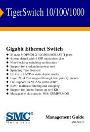
<strong>TigerSwitch</strong> <strong>10</strong>/<strong>10</strong>0/<strong>10</strong>00<br />
Gigabit Ethernet Switch<br />
◆ 24 auto-MDI/MDI-X <strong>10</strong>/<strong>10</strong>0/<strong>10</strong>00BASE-T ports<br />
◆ 4 ports shared with 4 SFP transceiver slots<br />
◆ Non-blocking switching architecture<br />
◆ Support for a redundant power unit<br />
◆ Spanning Tree Protocol<br />
◆ Up to six LACP or static 4-port trunks<br />
◆ CoS support through eight priority queues<br />
◆ Full support for VLANs with GVRP<br />
◆ IGMP multicast filtering and snooping<br />
◆ Support for jumbo frames up to 9 KB<br />
◆ Manageable via console, Web, SNMP/RMON<br />
<strong>Installation</strong> <strong>Guide</strong><br />
<strong>SMC</strong>8624T
<strong>TigerSwitch</strong> <strong>10</strong>/<strong>10</strong>0/<strong>10</strong>00<br />
<strong>Installation</strong> <strong>Guide</strong><br />
From <strong>SMC</strong>’s Tiger line of feature-rich workgroup LAN solutions<br />
38 Tesla<br />
Irvine, CA 92618<br />
Phone: (949) 679-8000<br />
October 2003<br />
Pub. # 150000041<strong>10</strong>0A
Information furnished by <strong>SMC</strong> Networks, Inc. (<strong>SMC</strong>) is believed to be<br />
accurate and reliable. However, no responsibility is assumed by <strong>SMC</strong> for its<br />
use, nor for any infringements of patents or other rights of third parties<br />
which may result from its use. No license is granted by implication or<br />
otherwise under any patent or patent rights of <strong>SMC</strong>. <strong>SMC</strong> reserves the<br />
right to change specifications at any time without notice.<br />
Trademarks:<br />
Copyright © 2003 by<br />
<strong>SMC</strong> Networks, Inc.<br />
38 Tesla<br />
Irvine, CA 92618<br />
All rights reserved. Printed in Taiwan<br />
<strong>SMC</strong> is a registered trademark; and EZ Switch, TigerStack and <strong>TigerSwitch</strong> are trademarks of <strong>SMC</strong><br />
Networks, Inc. Other product and company names are trademarks or registered trademarks of their<br />
respective holders.
LIMITED WARRANTY<br />
Limited Warranty Statement: <strong>SMC</strong> Networks, Inc. (“<strong>SMC</strong>”) warrants its products to be free<br />
from defects in workmanship and materials, under normal use and service, for the applicable<br />
warranty term. All <strong>SMC</strong> products carry a standard 90-day limited warranty from the date of<br />
purchase from <strong>SMC</strong> or its Authorized Reseller. <strong>SMC</strong> may, at its own discretion, repair or<br />
replace any product not operating as warranted with a similar or functionally equivalent<br />
product, during the applicable warranty term. <strong>SMC</strong> will endeavor to repair or replace any<br />
product returned under warranty within 30 days of receipt of the product.<br />
The standard limited warranty can be upgraded to a Limited Lifetime* warranty by registering<br />
new products within 30 days of purchase from <strong>SMC</strong> or its Authorized Reseller. Registration<br />
can be accomplished via the enclosed product registration card or online via the <strong>SMC</strong> Web<br />
site. Failure to register will not affect the standard limited warranty. The Limited Lifetime<br />
warranty covers a product during the Life of that Product, which is defined as the period of<br />
time during which the product is an “Active” <strong>SMC</strong> product. A product is considered to be<br />
“Active” while it is listed on the current <strong>SMC</strong> price list. As new technologies emerge, older<br />
technologies become obsolete and <strong>SMC</strong> will, at its discretion, replace an older product in its<br />
product line with one that incorporates these newer technologies. At that point, the obsolete<br />
product is discontinued and is no longer an “Active” <strong>SMC</strong> product. A list of discontinued<br />
products with their respective dates of discontinuance can be found at:<br />
http://www.smc.com/index.cfm?action=customer_service_warranty.<br />
All products that are replaced become the property of <strong>SMC</strong>. Replacement products may be<br />
either new or reconditioned. Any replaced or repaired product carries either a 30-day limited<br />
warranty or the remainder of the initial warranty, whichever is longer. <strong>SMC</strong> is not responsible<br />
for any custom software or firmware, configuration information, or memory data of<br />
Customer contained in, stored on, or integrated with any products returned to <strong>SMC</strong> pursuant<br />
to any warranty. Products returned to <strong>SMC</strong> should have any customer-installed accessory or<br />
add-on components, such as expansion modules, removed prior to returning the product for<br />
replacement. <strong>SMC</strong> is not responsible for these items if they are returned with the product.<br />
Customers must contact <strong>SMC</strong> for a Return Material Authorization number prior to returning<br />
any product to <strong>SMC</strong>. Proof of purchase may be required. Any product returned to <strong>SMC</strong><br />
without a valid Return Material Authorization (RMA) number clearly marked on the outside<br />
of the package will be returned to customer at customer’s expense. For warranty claims within<br />
North America, please call our toll-free customer support number at (800) 762-4968.<br />
Customers are responsible for all shipping charges from their facility to <strong>SMC</strong>. <strong>SMC</strong> is<br />
responsible for return shipping charges from <strong>SMC</strong> to customer.<br />
i
ii<br />
WARRANTIES EXCLUSIVE: IF AN <strong>SMC</strong> PRODUCT DOES NOT OPERATE AS<br />
WARRANTED ABOVE, CUSTOMER’S SOLE REMEDY SHALL BE REPAIR OR<br />
REPLACEMENT OF THE PRODUCT IN QUESTION, AT <strong>SMC</strong>’S OPTION. THE<br />
FOREGOING WARRANTIES AND REMEDIES ARE EXCLUSIVE AND ARE IN<br />
LIEU OF ALL OTHER WARRANTIES OR CONDITIONS, EXPRESS OR IMPLIED,<br />
EITHER IN FACT OR BY OPERATION OF LAW, STATUTORY OR OTHERWISE,<br />
INCLUDING WARRANTIES OR CONDITIONS OF MERCHANTABILITY AND<br />
FITNESS FOR A PARTICULAR PURPOSE. <strong>SMC</strong> NEITHER ASSUMES NOR<br />
AUTHORIZES ANY OTHER PERSON TO ASSUME FOR IT ANY OTHER<br />
LIABILITY IN CONNECTION WITH THE SALE, INSTALLATION,<br />
MAINTENANCE OR USE OF ITS PRODUCTS. <strong>SMC</strong> SHALL NOT BE LIABLE<br />
UNDER THIS WARRANTY IF ITS TESTING AND EXAMINATION DISCLOSE THE<br />
ALLEGED DEFECT IN THE PRODUCT DOES NOT EXIST OR WAS CAUSED BY<br />
CUSTOMER’S OR ANY THIRD PERSON’S MISUSE, NEGLECT, IMPROPER<br />
INSTALLATION OR TESTING, UNAUTHORIZED ATTEMPTS TO REPAIR, OR<br />
ANY OTHER CAUSE BEYOND THE RANGE OF THE INTENDED USE, OR BY<br />
ACCIDENT, FIRE, LIGHTNING, OR OTHER HAZARD.<br />
LIMITATION OF LIABILITY: IN NO EVENT, WHETHER BASED IN CONTRACT<br />
OR TORT (INCLUDING NEGLIGENCE), SHALL <strong>SMC</strong> BE LIABLE FOR<br />
INCIDENTAL, CONSEQUENTIAL, INDIRECT, SPECIAL, OR PUNITIVE<br />
DAMAGES OF ANY KIND, OR FOR LOSS OF REVENUE, LOSS OF BUSINESS, OR<br />
OTHER FINANCIAL LOSS ARISING OUT OF OR IN CONNECTION WITH THE<br />
SALE, INSTALLATION, MAINTENANCE, USE, PERFORMANCE, FAILURE, OR<br />
INTERRUPTION OF ITS PRODUCTS, EVEN IF <strong>SMC</strong> OR ITS AUTHORIZED<br />
RESELLER HAS BEEN ADVISED OF THE POSSIBILITY OF SUCH DAMAGES.<br />
SOME STATES DO NOT ALLOW THE EXCLUSION OF IMPLIED WARRANTIES<br />
OR THE LIMITATION OF INCIDENTAL OR CONSEQUENTIAL DAMAGES FOR<br />
CONSUMER PRODUCTS, SO THE ABOVE LIMITATIONS AND EXCLUSIONS<br />
MAY NOT APPLY TO YOU. THIS WARRANTY GIVES YOU SPECIFIC LEGAL<br />
RIGHTS, WHICH MAY VARY FROM STATE TO STATE. NOTHING IN THIS<br />
WARRANTY SHALL BE TAKEN TO AFFECT YOUR STATUTORY RIGHTS.<br />
* <strong>SMC</strong> will provide warranty service for one year following discontinuance from the active<br />
<strong>SMC</strong> price list. Under the limited lifetime warranty, internal and external power supplies, fans,<br />
and cables are covered by a standard one-year warranty from date of purchase.<br />
<strong>SMC</strong> Networks, Inc.<br />
38 Tesla<br />
Irvine, CA 92618
FCC - Class A<br />
COMPLIANCES<br />
This equipment generates, uses, and can radiate radio frequency energy and, if not installed<br />
and used in accordance with the instruction manual, may cause interference to radio<br />
communications. It has been tested and found to comply with the limits for a Class A<br />
computing device pursuant to Subpart B of Part 15 of FCC Rules, which are designed to<br />
provide reasonable protection against such interference when operated in a commercial<br />
environment. Operation of this equipment in a residential area is likely to cause interference,<br />
in which case the user, at his own expense, will be required to take whatever measures may be<br />
required to correct the interference. You are cautioned that changes or modifications not<br />
expressly approved by the party responsible for compliance could void your authority to<br />
operate the equipment.<br />
You may use unshielded twisted-pair (UTP) cable for RJ-45 connections—Category 3 or<br />
greater for <strong>10</strong> Mbps connections, Category 5 for <strong>10</strong>0 Mbps connections and Category 5 or 5e<br />
for <strong>10</strong>00 Mbps connections. Use 50/125 or 62.5/125 micron multimode fiber optic cable, or<br />
9/125 micron single-mode cable, for SFP transceiver connections.<br />
Warnings: 1. Wear an anti-static wrist strap or take other suitable measures to prevent<br />
electrostatic discharge when handling this equipment.<br />
2. When connecting this switch to a power outlet, connect the field ground<br />
lead on the tri-pole power plug to a valid earth ground line to prevent electrical<br />
hazards.<br />
EC Conformance Declaration - Class A<br />
<strong>SMC</strong> contact for these products in Europe is:<br />
<strong>SMC</strong> Networks Europe,<br />
Edificio Conata II,<br />
Calle Fructuós Gelabert 6-8, 2o , 4a ,<br />
08970 - Sant Joan Despí, Barcelona, Spain.<br />
This information technology equipment complies with the requirements of the Council<br />
Directive 89/336/EEC on the Approximation of the laws of the Member States relating to<br />
Electromagnetic Compatibility and 73/23/EEC for electrical equipment used within certain<br />
iii
COMPLIANCES<br />
iv<br />
voltage limits and the Amendment Directive 93/68/EEC. For the evaluation of the<br />
compliance with these Directives, the following standards were applied:<br />
RFI Emission: • Limit class A according to EN 55022:1998<br />
• Limit class A for harmonic current emission according to<br />
EN 6<strong>10</strong>00-3-2/1995<br />
• Limitation of voltage fluctuation and flicker in low-voltage supply<br />
system according to EN 6<strong>10</strong>00-3-3/1995<br />
Immunity: • Product family standard according to EN 55024:1998<br />
• Electrostatic Discharge according to EN 6<strong>10</strong>00-4-2:1995<br />
(Contact Discharge: ±4 kV, Air Discharge: ±8 kV)<br />
• Radio-frequency electromagnetic field according to EN 6<strong>10</strong>00-4-3:1996<br />
(80 - <strong>10</strong>00 MHz with 1 kHz AM 80% Modulation: 3 V/m)<br />
• Electrical fast transient/burst according to EN 6<strong>10</strong>00-4-4:1995 (AC/<br />
DC power supply: ±1 kV, Data/Signal lines: ±0.5 kV)<br />
• Surge immunity test according to EN 6<strong>10</strong>00-4-5:1995<br />
(AC/DC Line to Line: ±1 kV, AC/DC Line to Earth: ±2 kV)<br />
• Immunity to conducted disturbances, Induced by radio-frequency<br />
fields: EN 6<strong>10</strong>00-4-6:1996 (0.15 - 80 MHz with<br />
1 kHz AM 80% Modulation: 3 V/m)<br />
• Power frequency magnetic field immunity test according to<br />
EN 6<strong>10</strong>00-4-8:1993 (1 A/m at frequency 50 Hz)<br />
• Voltage dips, short interruptions and voltage variations immunity test<br />
according to EN 6<strong>10</strong>00-4-11:1994 (>95% Reduction @<strong>10</strong> ms, 30%<br />
Reduction @500 ms, >95% Reduction @5000 ms)<br />
LVD: • EN 60950 (A1/1992; A2/1993; A3/1993; A4/1995; A11/1997)<br />
Warning: Do not plug a phone jack connector in the RJ-45 port. This may damage this<br />
device. Les raccordeurs ne sont pas utilisé pour le systéme téléphonique!
Industry Canada - Class A<br />
COMPLIANCES<br />
This digital apparatus does not exceed the Class A limits for radio noise emissions from<br />
digital apparatus as set out in the interference-causing equipment standard entitled “Digital<br />
Apparatus,” ICES-003 of the Department of Communications.<br />
Cet appareil numérique respecte les limites de bruits radioélectriques applicables aux appareils<br />
numériques de Classe A prescrites dans la norme sur le matériel brouilleur: “Appareils<br />
Numériques,” NMB-003 édictée par le ministère des Communications.<br />
Japan VCCI Class A<br />
Taiwan BSMI Class A<br />
Australia AS/NZS 3548 (1995) - Class A<br />
<strong>SMC</strong> contact for products in Australia is:<br />
<strong>SMC</strong> Communications Pty. Ltd.<br />
Suite 18, 12 Tryon Road,<br />
Lindfield NSW2070,<br />
Phone: 61-2-94160437<br />
Fax: 61-2-94160474<br />
v
COMPLIANCES<br />
vi<br />
Safety Compliance<br />
Warning: Fiber Optic Port Safety<br />
CLASS I<br />
LASER DEVICE<br />
Avertissment: Ports pour fibres optiques - sécurité sur le plan<br />
optique<br />
DISPOSITIF LASER<br />
DE CLASSE I<br />
Warnhinweis: Faseroptikanschlüsse - Optische Sicherheit<br />
LASERGERÄT<br />
DER KLASSE I<br />
Underwriters Laboratories Compliance Statement<br />
When using a fiber optic port, never look at the transmit<br />
laser while it is powered on. Also, never look directly at the<br />
fiber TX port and fiber cable ends when they are powered<br />
on.<br />
Ne regardez jamais le laser tant qu’il est sous tension. Ne<br />
regardez jamais directement le port TX (Transmission) à<br />
fibres optiques et les embouts de câbles à fibres optiques<br />
tant qu’ils sont sous tension.<br />
Niemals ein Übertragungslaser betrachten, während dieses<br />
eingeschaltet ist. Niemals direkt auf den<br />
Faser-TX-Anschluß und auf die Faserkabelenden schauen,<br />
während diese eingeschaltet sind.<br />
Important! Before making connections, make sure you have the correct cord set. Check it<br />
(read the label on the cable) against the following:<br />
Operating Voltage Cord Set Specifications<br />
120 Volts UL Listed/CSA Certified Cord Set<br />
Minimum 18 AWG<br />
Type SVT or SJT three conductor cord<br />
Maximum length of 15 feet<br />
Parallel blade, grounding type attachment plug rated<br />
15 A, 125 V<br />
240 Volts (Europe only) Cord Set with H05VV-F cord having three<br />
conductors with minimum diameter of 0.75 mm2 IEC-320 receptacle<br />
Male plug rated <strong>10</strong> A, 250 V<br />
The unit automatically matches the connected input voltage. Therefore, no additional<br />
adjustments are necessary when connecting it to any input voltage within the range marked<br />
on the rear panel.
Wichtige Sicherheitshinweise (Germany)<br />
COMPLIANCES<br />
1. Bitte lesen Sie diese Hinweise sorgfältig durch.<br />
2. Heben Sie diese Anleitung für den späteren Gebrauch auf.<br />
3. Vor jedem Reinigen ist das Gerät vom Stromnetz zu trennen. Verwenden Sie keine<br />
Flüssigoder Aerosolreiniger. Am besten eignet sich ein angefeuchtetes Tuch zur<br />
Reinigung.<br />
4. Die Netzanschlu ßsteckdose soll nahe dem Gerät angebracht und leicht zugänglich sein.<br />
5. Das Gerät ist vor Feuchtigkeit zu schützen.<br />
6. Bei der Aufstellung des Gerätes ist auf sicheren Stand zu achten. Ein Kippen oder Fallen<br />
könnte Beschädigungen hervorrufen.<br />
7. Die Belüftungsöffnungen dienen der Luftzirkulation, die das Gerät vor Überhitzung<br />
schützt. Sorgen Sie dafür, daß diese Öffnungen nicht abgedeckt werden.<br />
8. Beachten Sie beim Anschluß an das Stromnetz die Anschlußwerte.<br />
9. Verlegen Sie die Netzanschlußleitung so, daß niemand darüber fallen kann. Es sollte auch<br />
nichts auf der Leitung abgestellt werden.<br />
<strong>10</strong>. Alle Hinweise und Warnungen, die sich am Gerät befinden, sind zu beachten.<br />
11. Wird das Gerät über einen längeren Zeitraum nicht benutzt, sollten Sie es vom Stromnetz<br />
trennen. Somit wird im Falle einer Überspannung eine Beschädigung vermieden.<br />
12. Durch die Lüftungsöffnungen dürfen niemals Gegenstände oder Flüssigkeiten in das<br />
Gerät gelangen. Dies könnte einen Brand bzw. elektrischen Schlag auslösen.<br />
13. Öffnen sie niemals das Gerät. Das Gerät darf aus Gründen der elektrischen Sicherheit<br />
nur von authorisiertem Servicepersonal geöffnet werden.<br />
14. Wenn folgende Situationen auftreten ist das Gerät vom Stromnetz zu trennen und von<br />
einer qualifizierten Servicestelle zu überprüfen:<br />
a. Netzkabel oder Netzstecker sind beschädigt.<br />
b. Flüssigkeit ist in das Gerät eingedrungen.<br />
c. Das Gerät war Feuchtigkeit ausgesetzt.<br />
d. Wenn das Gerät nicht der Bedienungsanleitung entsprechend funktioniert oder Sie<br />
mit Hilfe dieser Anleitung keine Verbesserung erzielen.<br />
e. Das Gerät ist gefallen und/oder das Gehäuse ist beschädigt.<br />
f. Wenn das Gerät deutliche Anzeichen eines Defektes aufweist.<br />
15. Zum Netzanschluß dieses Gerätes ist eine geprüfte Leitung zu verwenden. Für einen<br />
Nennstrom bis 6 A und einem Gerätegewicht größer 3 kg ist eine Leitung nicht leichter<br />
als H05VV-F, 3G, 0.75 mm2 einzusetzen.<br />
Der arbeitsplatzbezogene Schalldruckpegel nach DIN 45 635 Teil <strong>10</strong>00 beträgt 70 dB(A) oder<br />
weniger.<br />
vii
COMPLIANCES<br />
viii
CONTENTS<br />
1 About the <strong>TigerSwitch</strong> <strong>10</strong>/<strong>10</strong>0/<strong>10</strong>00 . . . . . . . . . . . . . . . . . 1-1<br />
Overview . . . . . . . . . . . . . . . . . . . . . . . . . . . . . . . . . . . . . . . . . . . . . . . . . . 1-1<br />
Switch Architecture . . . . . . . . . . . . . . . . . . . . . . . . . . . . . . . . . . . 1-2<br />
Management Options . . . . . . . . . . . . . . . . . . . . . . . . . . . . . . . . . . 1-2<br />
Description of Hardware . . . . . . . . . . . . . . . . . . . . . . . . . . . . . . . . . . . . . 1-3<br />
<strong>10</strong>/<strong>10</strong>0/<strong>10</strong>00BASE-T Ports . . . . . . . . . . . . . . . . . . . . . . . . . . . . . 1-3<br />
SFP Slots . . . . . . . . . . . . . . . . . . . . . . . . . . . . . . . . . . . . . . . . . . . . 1-3<br />
Status LEDs . . . . . . . . . . . . . . . . . . . . . . . . . . . . . . . . . . . . . . . . . 1-4<br />
Optional Redundant Power Unit . . . . . . . . . . . . . . . . . . . . . . . . . 1-6<br />
Power Supply Receptacles . . . . . . . . . . . . . . . . . . . . . . . . . . . . . . 1-6<br />
Features and Benefits . . . . . . . . . . . . . . . . . . . . . . . . . . . . . . . . . . . . . . . . 1-7<br />
Connectivity . . . . . . . . . . . . . . . . . . . . . . . . . . . . . . . . . . . . . . . . . 1-7<br />
Expandability . . . . . . . . . . . . . . . . . . . . . . . . . . . . . . . . . . . . . . . . 1-7<br />
Performance . . . . . . . . . . . . . . . . . . . . . . . . . . . . . . . . . . . . . . . . . 1-7<br />
Management . . . . . . . . . . . . . . . . . . . . . . . . . . . . . . . . . . . . . . . . . 1-8<br />
2 Network Planning . . . . . . . . . . . . . . . . . . . . . . . . . . . . . . . . 2-1<br />
Introduction to Switching . . . . . . . . . . . . . . . . . . . . . . . . . . . . . . . . . . . . 2-1<br />
Application Examples . . . . . . . . . . . . . . . . . . . . . . . . . . . . . . . . . . . . . . . 2-2<br />
Collapsed Backbone . . . . . . . . . . . . . . . . . . . . . . . . . . . . . . . . . . . 2-2<br />
Network Aggregation Plan . . . . . . . . . . . . . . . . . . . . . . . . . . . . . . 2-3<br />
Remote Connections with Fiber Cable . . . . . . . . . . . . . . . . . . . . 2-4<br />
Making VLAN Connections . . . . . . . . . . . . . . . . . . . . . . . . . . . . 2-5<br />
Application Notes . . . . . . . . . . . . . . . . . . . . . . . . . . . . . . . . . . . . . . . . . . 2-6<br />
3 Installing the Switch . . . . . . . . . . . . . . . . . . . . . . . . . . . . . . 3-1<br />
Selecting a Site . . . . . . . . . . . . . . . . . . . . . . . . . . . . . . . . . . . . . . . . . . . . . 3-1<br />
Ethernet Cabling . . . . . . . . . . . . . . . . . . . . . . . . . . . . . . . . . . . . . . . . . . . 3-2<br />
Equipment Checklist . . . . . . . . . . . . . . . . . . . . . . . . . . . . . . . . . . . . . . . . 3-3<br />
Package Contents . . . . . . . . . . . . . . . . . . . . . . . . . . . . . . . . . . . . . 3-3<br />
Optional Rack-Mounting Equipment . . . . . . . . . . . . . . . . . . . . . 3-3<br />
Mounting . . . . . . . . . . . . . . . . . . . . . . . . . . . . . . . . . . . . . . . . . . . . . . . . . 3-4<br />
Rack Mounting . . . . . . . . . . . . . . . . . . . . . . . . . . . . . . . . . . . . . . . 3-4<br />
Desktop or Shelf Mounting . . . . . . . . . . . . . . . . . . . . . . . . . . . . . 3-6<br />
Installing an Optional SFP Transceiver into the Switch . . . . . . . 3-7<br />
ix
CONTENTS<br />
x<br />
Connecting to a Power Source . . . . . . . . . . . . . . . . . . . . . . . . . . . . . . . . 3-8<br />
Connecting to the Console Port . . . . . . . . . . . . . . . . . . . . . . . . . . . . . . . 3-9<br />
Wiring Map for Serial Cable . . . . . . . . . . . . . . . . . . . . . . . . . . . . . 3-9<br />
4 Making Network Connections . . . . . . . . . . . . . . . . . . . . . . .4-1<br />
Connecting Network Devices . . . . . . . . . . . . . . . . . . . . . . . . . . . . . . . . . 4-1<br />
Twisted-Pair Devices . . . . . . . . . . . . . . . . . . . . . . . . . . . . . . . . . . . . . . . . 4-1<br />
Cabling <strong>Guide</strong>lines . . . . . . . . . . . . . . . . . . . . . . . . . . . . . . . . . . . . 4-1<br />
Connecting to PCs, Servers, Hubs and Switches . . . . . . . . . . . . 4-2<br />
Network Wiring Connections . . . . . . . . . . . . . . . . . . . . . . . . . . . 4-3<br />
Connectivity Rules . . . . . . . . . . . . . . . . . . . . . . . . . . . . . . . . . . . . . . . . . . 4-4<br />
<strong>10</strong>00BASE-T Cable Requirements . . . . . . . . . . . . . . . . . . . . . . . 4-4<br />
<strong>10</strong>00 Mbps Gigabit Ethernet Collision Domain . . . . . . . . . . . . . 4-4<br />
<strong>10</strong>0 Mbps Fast Ethernet Collision Domain . . . . . . . . . . . . . . . . 4-5<br />
<strong>10</strong> Mbps Ethernet Collision Domain . . . . . . . . . . . . . . . . . . . . . 4-5<br />
Cable Labeling and Connection Records . . . . . . . . . . . . . . . . . . . . . . . . 4-6
APPENDICES:<br />
CONTENTS<br />
A Troubleshooting . . . . . . . . . . . . . . . . . . . . . . . . . . . . . . . . . A-1<br />
Diagnosing Switch Indicators . . . . . . . . . . . . . . . . . . . . . . . . . . . . . . . . . A-1<br />
Power and Cooling Problems . . . . . . . . . . . . . . . . . . . . . . . . . . . . . . . . . A-1<br />
<strong>Installation</strong> . . . . . . . . . . . . . . . . . . . . . . . . . . . . . . . . . . . . . . . . . . . . . . . . A-2<br />
In-Band Access . . . . . . . . . . . . . . . . . . . . . . . . . . . . . . . . . . . . . . . . . . . . A-2<br />
B Cables . . . . . . . . . . . . . . . . . . . . . . . . . . . . . . . . . . . . . . . . . B-1<br />
Specifications . . . . . . . . . . . . . . . . . . . . . . . . . . . . . . . . . . . . . . . . . . . . . . B-1<br />
Twisted-Pair Cable and Pin Assignments . . . . . . . . . . . . . . . . . . . . . . . . B-2<br />
<strong>10</strong>BASE-T/<strong>10</strong>0BASE-TX Pin Assignments . . . . . . . . . . . . . . . . B-2<br />
<strong>10</strong>00BASE-T Pin Assignments . . . . . . . . . . . . . . . . . . . . . . . . . . B-3<br />
<strong>10</strong>00BASE-T Cable Requirements . . . . . . . . . . . . . . . . . . . . . . . B-4<br />
Fiber Standards . . . . . . . . . . . . . . . . . . . . . . . . . . . . . . . . . . . . . . . . . . . . . B-5<br />
C Specifications . . . . . . . . . . . . . . . . . . . . . . . . . . . . . . . . . . . C-1<br />
Physical Characteristics . . . . . . . . . . . . . . . . . . . . . . . . . . . . . . . . . . . . . . C-1<br />
Compliances . . . . . . . . . . . . . . . . . . . . . . . . . . . . . . . . . . . . . . . . . . . . . . . C-2<br />
Warranty . . . . . . . . . . . . . . . . . . . . . . . . . . . . . . . . . . . . . . . . . . . . . . . . . . C-3<br />
D Ordering Information . . . . . . . . . . . . . . . . . . . . . . . . . . . . . D-1<br />
Glossary<br />
Index<br />
xi
CONTENTS<br />
xii
CHAPTER 1<br />
ABOUT THE<br />
TIGERSWITCH <strong>10</strong>/<strong>10</strong>0/<strong>10</strong>00<br />
Overview<br />
DC IN<br />
12V 8.5A<br />
<strong>SMC</strong>’s <strong>TigerSwitch</strong> <strong>10</strong>/<strong>10</strong>0/<strong>10</strong>00 is an intelligent multilayer switch (Layer 2<br />
and 4) with 24 <strong>10</strong>/<strong>10</strong>0/<strong>10</strong>00BASE-T ports, four of which are combination<br />
ports that are shared with four SFP transceiver slots. There is also an<br />
SNMP-based management agent embedded on the main board. This agent<br />
supports both in-band and out-of-band access for managing the switch.<br />
This switch provides a broad range of powerful features for Layer 2<br />
switching, delivering reliability and consistent performance for your<br />
network traffic. It brings order to poorly performing networks by<br />
segregating them into separate broadcast domains with IEEE 802.1Q<br />
compliant VLANs, and empowers multimedia applications with multicast<br />
switching and CoS services.<br />
1 3 5 7<br />
2 4 6 8<br />
<strong>10</strong>/<strong>10</strong>0/<strong>10</strong>00 Mbps RJ-45 Ports<br />
Redundant Power socket Port Status Indicators<br />
Power Socket<br />
RPU<br />
9 11 13 15<br />
<strong>10</strong> 12 14 16<br />
17 19 21 23<br />
18 20 22 24<br />
Figure 1-1. Front and Rear Panels<br />
SFP Slots System Indicators<br />
21 22 23 24<br />
<strong>TigerSwitch</strong> <strong>10</strong>/<strong>10</strong>0/<strong>10</strong>00<br />
8624T<br />
<strong>10</strong>00=Yellow <strong>10</strong>0=Green <strong>10</strong>=Flashing Green R01<br />
RPU<br />
Console Port<br />
<strong>10</strong>0-240V~, 50-60Hz 2A<br />
1-1
ABOUT THE TIGERSWITCH <strong>10</strong>/<strong>10</strong>0/<strong>10</strong>00<br />
Switch Architecture<br />
1-2<br />
The <strong>TigerSwitch</strong> <strong>10</strong>/<strong>10</strong>0/<strong>10</strong>00 employs a wire-speed, non-blocking<br />
switching fabric. This permits simultaneous wire-speed transport of<br />
multiple packets at low latency on all ports. This switch also features<br />
full-duplex capability on all ports, which effectively doubles the bandwidth<br />
of each connection.<br />
The switch uses store-and-forward switching to ensure maximum data<br />
integrity. With store-and-forward switching, the entire packet must be<br />
received into a buffer and checked for validity before being forwarded.<br />
This prevents errors from being propagated throughout the network.<br />
Management Options<br />
This switch contains a comprehensive array of LEDs for “at-a-glance”<br />
monitoring of network and port status. It also includes a management<br />
agent that allows you to configure or monitor the switch using its<br />
embedded management software, or via SNMP applications. To manage<br />
the switch, you can make a direct connection to the RS-232 console port<br />
(out-of-band), or you can manage the switch through a network<br />
connection (in-band) using Telnet, the on-board Web agent, or<br />
Windows-based network management software.<br />
For a detailed description of the switch's advanced features, refer to the<br />
Management <strong>Guide</strong>.
Description of Hardware<br />
<strong>10</strong>/<strong>10</strong>0/<strong>10</strong>00BASE-T Ports<br />
SFP Slots<br />
DESCRIPTION OF HARDWARE<br />
These ports are RJ-45 ports that operate at <strong>10</strong> Mbps or <strong>10</strong>0 Mbps, half or<br />
full duplex, or at <strong>10</strong>00 Mbps, full duplex. Because all ports on this switch<br />
support automatic MDI/MDI-X operation, you can use straight-through<br />
cables for all network connections to PCs or servers, or to other switches<br />
or hubs. (See “<strong>10</strong>00BASE-T Pin Assignments” on page B-3.)<br />
Each of these ports support auto-negotiation, so the optimum<br />
transmission mode (half or full duplex), and data rate (<strong>10</strong>, <strong>10</strong>0, or<br />
<strong>10</strong>00 Mbps) can be selected automatically. If a device connected to one of<br />
these ports does not support auto-negotiation, the communication mode<br />
of that port can be configured manually.<br />
Each port also supports auto-negotiation of flow control, so the switch<br />
can automatically prevent port buffers from becoming saturated.<br />
The Small Form Factor Pluggable (SFP) transceiver slots are shared with<br />
four of the RJ-45 ports (Ports 21~24). In its default configuration, if an<br />
SFP transceiver (purchased separately) is installed in a slot and has a valid<br />
link on its port, the associated RJ-45 port is disabled and cannot be used.<br />
The switch can also be configured to force the use of an RJ-45 port or SFP<br />
slot, as required.<br />
1-3
ABOUT THE TIGERSWITCH <strong>10</strong>/<strong>10</strong>0/<strong>10</strong>00<br />
Status LEDs<br />
1-4<br />
The LEDs, which are located on the front panel for easy viewing, are<br />
shown below and described in the following table.<br />
24<br />
SFP LEDs<br />
Figure 1-2. Port and System LEDs<br />
Port Status LEDs<br />
LED Condition Status<br />
RJ-45 Ports<br />
Link On Yellow Port has established a valid <strong>10</strong>00 Mbps network<br />
connection.<br />
On Green Port has established a valid <strong>10</strong>0 Mbps network<br />
connection.<br />
Flashing Green Port has established a valid <strong>10</strong> Mbps network<br />
connection.<br />
Flashing Yellow The port has been disabled.<br />
Act. Flashing Green Traffic is passing through the port.<br />
SFP Transceivers Slots<br />
(Ports<br />
21~24)<br />
<strong>10</strong>00=Yellow <strong>10</strong>0=Green <strong>10</strong>=Flashing Green<br />
Link<br />
1 3 5 7 9 11 13 15 17 19 21 23<br />
Act<br />
Link<br />
2 4 6 8 <strong>10</strong> 12 14 16 18 20 22 24<br />
Act<br />
<strong>10</strong>00=Yellow <strong>10</strong>0=Green <strong>10</strong>=Flashing Green<br />
Power<br />
Diag<br />
RPU<br />
Link/Speed<br />
Off There is no traffic passing through the port.<br />
On Green An SFP transceiver port has established a valid<br />
<strong>10</strong>00 Mbps network connection. The associated<br />
RJ-45 port is disabled.<br />
Off An SFP transceiver port has no valid link. The<br />
associated RJ-45 port is enabled.<br />
Console<br />
Activity
24<br />
Power Indicator<br />
<strong>10</strong>00=Yellow <strong>10</strong>0=Green <strong>10</strong>=Flashing Green<br />
Link<br />
1 3 5 7 9 11 13 15 17 19 21 23<br />
Act<br />
Link<br />
2 4 6 8 <strong>10</strong> 12 14 16 18 20 22 24<br />
Act<br />
<strong>10</strong>00=Yellow <strong>10</strong>0=Green <strong>10</strong>=Flashing Green<br />
System Status LEDs<br />
LED Condition Status<br />
DESCRIPTION OF HARDWARE<br />
Power On Green The unit’s internal power supply is operating<br />
normally.<br />
Off The unit has no power connected.<br />
Diag. Flashing<br />
Green<br />
The system diagnostic test is in progress.<br />
On Green The system diagnostic test has completed<br />
successfully.<br />
On Red The system diagnostic test has detected a fault.<br />
RPU On Green The redundant power unit is operating<br />
normally.<br />
Power<br />
Diag<br />
RPU<br />
Console<br />
Diagnostic Indicator<br />
Redundant Power Indicator<br />
Off No redundant power unit is connected.<br />
1-5
ABOUT THE TIGERSWITCH <strong>10</strong>/<strong>10</strong>0/<strong>10</strong>00<br />
Optional Redundant Power Unit<br />
1-6<br />
<strong>SMC</strong> provides an optional Redundant Power Unit (RPU), <strong>SMC</strong>RPU600W,<br />
that can supply power to the switch in the event of failure of the internal<br />
power supply.<br />
Power Supply Receptacles<br />
DC IN<br />
12V 8.5A<br />
There are two power receptacles on the rear panel of the switch. The<br />
standard power receptacle is for the AC power cord. The receptacle<br />
labeled “RPU” is for the optional Redundant Power Unit.<br />
RPU<br />
Figure 1-3. Power Supply Receptacles<br />
<strong>10</strong>0-240V~, 50-60Hz 2A
Features and Benefits<br />
Connectivity<br />
FEATURES AND BENEFITS<br />
◆ 24 dual-speed ports for easy Gigabit Ethernet integration and for<br />
protection of your investment in legacy LAN equipment.<br />
◆ Auto-negotiation enables each RJ-45 port to automatically select the<br />
optimum communication mode (half or full duplex) if this feature is<br />
supported by the attached device; otherwise the port can be configured<br />
manually.<br />
◆ Independent RJ-45 <strong>10</strong>/<strong>10</strong>0/<strong>10</strong>00BASE-T ports with auto MDI/<br />
MDI-X pinout selection.<br />
◆ Unshielded (UTP) cable supported on all RJ-45 ports: Category 3, 4 or<br />
5 for <strong>10</strong> Mbps connections, Category 5 or 5e for <strong>10</strong>0 Mbps<br />
connections, and Category 5 or better for <strong>10</strong>00 Mbps connections.<br />
◆ IEEE 802.3 Ethernet, 802.3u Fast Ethernet, 802.3z and 802.3ab<br />
Gigabit Ethernet compliance ensures compatibility with<br />
standards-based hubs, network cards and switches from any vendor.<br />
Expandability<br />
◆ Supports <strong>10</strong>00BASE-SX and <strong>10</strong>00BASE-LX SFP transceivers.<br />
Performance<br />
◆ Transparent bridging<br />
◆ Switching table with a total of 16K MAC address entries<br />
◆ Provides store-and-forward switching<br />
◆ Supports wire-speed switching<br />
◆ Supports flow control, using back pressure for half duplex and IEEE<br />
802.3x for full duplex<br />
1-7
ABOUT THE TIGERSWITCH <strong>10</strong>/<strong>10</strong>0/<strong>10</strong>00<br />
1-8<br />
◆ Broadcast storm control<br />
◆ Desktop or rack-mountable<br />
◆ Limited lifetime warranty<br />
Management<br />
◆ “At-a-glance” LEDs for easy troubleshooting<br />
◆ Network management agent:<br />
• Manages switch in-band or out-of-band<br />
• Supports Telnet, SNMP/RMON and Web-based interface
Introduction to Switching<br />
CHAPTER 2<br />
NETWORK PLANNING<br />
A network switch allows simultaneous transmission of multiple packets via<br />
non-crossbar switching. This means that it can partition a network more<br />
efficiently than bridges or routers. The switch has, therefore, been<br />
recognized as one of the most important building blocks for today's<br />
networking technology.<br />
When performance bottlenecks are caused by congestion at the network<br />
access point (such as the network card for a high-volume file server), the<br />
device experiencing congestion (server, power user or hub) can be attached<br />
directly to a switched port. And, by using full-duplex mode, the bandwidth<br />
of the dedicated segment can be doubled to maximize throughput.<br />
When networks are based on repeater (hub) technology, the maximum<br />
distance between end stations is limited. For Ethernet, there may be up to<br />
four hubs between any pair of stations; for Fast Ethernet, the maximum is<br />
two. This is known as the hop count. However, a switch turns the hop<br />
count back to zero. So subdividing the network into smaller and more<br />
manageable segments, and linking them to the larger network by means of<br />
a switch, removes this limitation.<br />
A switch can be easily configured in any Ethernet or Fast Ethernet<br />
network to significantly boost bandwidth while using conventional cabling<br />
and network cards.<br />
2-1
NETWORK PLANNING<br />
Application Examples<br />
2-2<br />
The <strong>TigerSwitch</strong> <strong>10</strong>/<strong>10</strong>0/<strong>10</strong>00 is not only designed to segment your<br />
network, but also to provide a wide range of options in setting up network<br />
connections and linking VLANs. Some typical applications are described<br />
below.<br />
Collapsed Backbone<br />
The <strong>TigerSwitch</strong> <strong>10</strong>/<strong>10</strong>0/<strong>10</strong>00 is an excellent choice for mixed Ethernet,<br />
Fast Ethernet, and Gigabit Ethernet installations where significant growth<br />
is expected in the near future. You can easily build on this basic<br />
configuration, adding direct full-duplex connections to workstations or<br />
servers. When the time comes for further expansion, just connect to<br />
another hub or switch using one of the Gigabit Ethernet ports built into<br />
the front panel or a Gigabit Ethernet port on a plug-in SFP transceiver.<br />
In the figure below, this switch is operating as a collapsed backbone for a<br />
small LAN. It is providing dedicated <strong>10</strong> Mbps full-duplex connections to<br />
workstations and <strong>10</strong>0 Mbps full-duplex connections to power users and<br />
servers.<br />
...<br />
1 3 5 7<br />
2 4 6 8<br />
Servers<br />
<strong>10</strong>0 Mbps<br />
Full Duplex<br />
9 11 13 15<br />
<strong>10</strong> 12 14 16<br />
17 19 21 23<br />
18 20 22 24<br />
... ...<br />
Workstations<br />
<strong>10</strong>0 Mbps<br />
Full Duplex<br />
21 22 23 24<br />
<strong>TigerSwitch</strong> <strong>10</strong>/<strong>10</strong>0/<strong>10</strong>00<br />
8624T<br />
Figure 2-1. Collapsed Backbone<br />
<strong>10</strong>00=Yellow <strong>10</strong>0=Green <strong>10</strong>=Flashing Green R01<br />
RPU<br />
Workstations<br />
<strong>10</strong> Mbps<br />
Full Duplex
Network Aggregation Plan<br />
APPLICATION EXAMPLES<br />
With 24 parallel bridging ports (i.e., 24 distinct collision domains), the<br />
Gigabit Ethernet Switch can collapse a complex network down into a<br />
single efficient bridged node, increasing overall bandwidth and<br />
throughput.<br />
In the figure below, the <strong>10</strong>/<strong>10</strong>0/<strong>10</strong>00BASE-T ports on the Gigabit<br />
Ethernet Switch are providing <strong>10</strong>00 Mbps connectivity for up to 24<br />
segments through stackable switches. In addition, the switch is also<br />
connecting several servers at <strong>10</strong>00 Mbps.<br />
.<br />
1<br />
1<br />
1 3 5 7<br />
2 4 6 8<br />
ES3526F<br />
ES3526F<br />
9 11 13 15<br />
<strong>10</strong> 12 14 16<br />
17 19 21 23<br />
18 20 22 24<br />
<strong>10</strong>/<strong>10</strong>0/<strong>10</strong>00 Mbps Segments<br />
... ...<br />
21 22 23 24<br />
<strong>TigerSwitch</strong> <strong>10</strong>/<strong>10</strong>0/<strong>10</strong>00<br />
8624T<br />
<strong>10</strong>00=Yellow <strong>10</strong>0=Green <strong>10</strong>=Flashing Green R01<br />
Figure 2-2. Network Aggregation Plan<br />
.<br />
RPU<br />
1<br />
1<br />
ES3526F<br />
ES3526F<br />
Server Farm<br />
2-3
NETWORK PLANNING<br />
Remote Connections with Fiber Cable<br />
2-4<br />
Fiber optic technology allows for longer cabling than any other media type.<br />
A <strong>10</strong>00BASE-SX (MMF) link can connect to a site up to 550 meters away,<br />
and a <strong>10</strong>00BASE-LX (SMF) link can run up to 5 km. This allows the<br />
Gigabit Ethernet Switch to serve as a collapsed backbone, providing direct<br />
connectivity for a widespread LAN.<br />
A <strong>10</strong>00BASE-SX SFP can be used for a high-speed connection between<br />
floors in the same building, and a <strong>10</strong>00BASE-LX SFP can be used to<br />
connect to other buildings in a campus setting.<br />
The figure below illustrates this switch connecting multiple segments with<br />
fiber cable.<br />
Server Farm<br />
Remote Switch<br />
25 26 1 2 3 4 5 6 13 14 15 16 17 18<br />
1 2 3 4 5 6 13 14 15 16 17 18<br />
Link<br />
25 26<br />
Act<br />
Console<br />
Link<br />
Power<br />
Act<br />
7 8 9 <strong>10</strong> 11 12 19 20 21 22 23 24<br />
Fault<br />
Reset Clear Self Fan<br />
Test Status<br />
7 8 9 <strong>10</strong> 11 12 19 20 21 22 23 24<br />
1 3 5 7<br />
2 4 6 8<br />
<strong>10</strong>00BASE-SX MMF<br />
(500 meters)<br />
Headquarters<br />
9 11 13 15<br />
<strong>10</strong> 12 14 16<br />
<strong>10</strong>/<strong>10</strong>0/<strong>10</strong>00 Mbps Segments<br />
17 19 21 23<br />
18 20 22 24<br />
Remote Switch<br />
... ...<br />
21 22 23 24<br />
25 26 1 2 3 4 5 6 13 14 15 16 17 18<br />
1 2 3 4 5 6 13 14 15 16 17 18<br />
Link<br />
25 26<br />
Act<br />
Console<br />
Link<br />
Power<br />
Act<br />
7 8 9 <strong>10</strong> 11 12 19 20 21 22 23 24<br />
Fault<br />
Reset Clear Self Fan<br />
Test Status<br />
7 8 9 <strong>10</strong> 11 12 19 20 21 22 23 24<br />
<strong>10</strong>00BASE-LX SMF<br />
(5 kilometers)<br />
Figure 2-3. Remote Connection with Fiber Cable<br />
<strong>TigerSwitch</strong> <strong>10</strong>/<strong>10</strong>0/<strong>10</strong>00<br />
8624T<br />
<strong>10</strong>00=Yellow <strong>10</strong>0=Green <strong>10</strong>=Flashing Green R01<br />
RPU
Making VLAN Connections<br />
APPLICATION EXAMPLES<br />
VLANs can be based on port groups, or each data frame can be explicitly<br />
tagged to identify the VLAN group to which it belongs. When using portbased<br />
VLANs, ports can either be assigned to one specific group or to all<br />
groups. Port-based VLANs are suitable for small networks. A single switch<br />
can be easily configured to support several VLAN groups for various<br />
organizational entities (such as Finance and Marketing).<br />
When you expand port-based VLANs across several switches, you need to<br />
make a separate connection for each VLAN group. This approach is,<br />
however, inconsistent with the Spanning Tree Protocol, which can easily<br />
segregate ports that belong to the same VLAN. When VLANs cross<br />
separate switches, you need to use VLAN tagging. This allows you to<br />
assign multiple VLAN groups to the "trunk" ports (that is, tagged ports)<br />
connecting different switches.<br />
R&D<br />
21 VLAN 1<br />
Tagged<br />
Ports<br />
Finance<br />
VLAN<br />
unaware<br />
VLAN 2<br />
switch<br />
Testing<br />
Marketing<br />
R&D<br />
Finance<br />
VLAN 3<br />
VLAN 4<br />
1 3 5 7<br />
2 4 6 8<br />
Untagged Ports<br />
9 11 13 15<br />
<strong>10</strong> 12 14 16<br />
17 19 21 23<br />
18 20 22 24<br />
Tagged Port<br />
Figure 2-4. Making VLAN Connections<br />
VLAN<br />
aware<br />
switch<br />
Note: When connecting to a switch that does not support IEEE 802.1Q<br />
VLAN tags, use untagged ports.<br />
VLAN 3<br />
22 23 24<br />
<strong>TigerSwitch</strong> <strong>10</strong>/<strong>10</strong>0/<strong>10</strong>00<br />
8624T<br />
<strong>10</strong>00=Yellow <strong>10</strong>0=Green <strong>10</strong>=Flashing Green R01<br />
RPU<br />
VLAN 1<br />
VLAN 2<br />
Testing<br />
2-5
NETWORK PLANNING<br />
Application Notes<br />
2-6<br />
1. Full-duplex operation only applies to point-to-point access (such as<br />
when a switch is attached to a workstation, server or another switch).<br />
When the switch is connected to a hub, both devices must operate in<br />
half-duplex mode.<br />
2. Avoid using flow control on a port connected to a hub unless it is<br />
actually required to solve a problem. Otherwise back pressure jamming<br />
signals may degrade overall performance for the segment attached to<br />
the hub.<br />
3. As a general rule the length of fiber optic cable for a single switched<br />
link should not exceed 550 m (1805 ft) for multimode fiber or 5 km<br />
(16404 ft) for single-mode fiber.<br />
However, power budget constraints must also be considered when<br />
calculating the maximum cable length for your specific environment.
Selecting a Site<br />
CHAPTER 3<br />
INSTALLING THE SWITCH<br />
<strong>TigerSwitch</strong> <strong>10</strong>/<strong>10</strong>0/<strong>10</strong>00 units can be mounted in a standard 19-inch<br />
equipment rack or on a flat surface. Be sure to follow the guidelines below<br />
when choosing a location.<br />
◆ The site should:<br />
• be at the center of all the devices you want to link and near a<br />
power outlet.<br />
• be able to maintain its temperature within 0 to 50 °C (32 to<br />
122 °F) and its humidity within 5% to 95%, non-condensing<br />
• provide adequate space (approximately two inches) on all sides for<br />
proper air flow<br />
• be accessible for installing, cabling and maintaining the devices<br />
• allow the status LEDs to be clearly visible<br />
◆ Make sure twisted-pair cable is always routed away from power lines,<br />
fluorescent lighting fixtures and other sources of electrical<br />
interference, such as radios and transmitters.<br />
◆ Make sure that a separate grounded power outlet that provides <strong>10</strong>0 to<br />
240 VAC, 50 to 60 Hz, is within 2.44 m (8 feet) of each device and is<br />
powered from an independent circuit breaker. As with any equipment,<br />
using a filter or surge suppressor is recommended.<br />
3-1
INSTALLING THE SWITCH<br />
Ethernet Cabling<br />
3-2<br />
To ensure proper operation when installing the switch into a network,<br />
make sure that the current cables are suitable for <strong>10</strong>BASE-T,<br />
<strong>10</strong>0BASE-TX or <strong>10</strong>00BASE-T operation. Check the following criteria<br />
against the current installation of your network:<br />
◆ Cable type: Unshielded twisted pair (UTP) or shielded twisted pair<br />
(STP) cables with RJ-45 connectors; Category 3 or better for<br />
<strong>10</strong>BASE-T, Category 5 or better for <strong>10</strong>0BASE-TX, and Category 5e or<br />
better for <strong>10</strong>00BASE-T.<br />
◆ Protection from radio frequency interference emissions<br />
◆ Electrical surge suppression<br />
◆ Separation of electrical wires (switch related or other) and<br />
electromagnetic fields from data based network wiring<br />
◆ Safe connections with no damaged cables, connectors or shields<br />
RJ-45 Connector<br />
Figure 3-1. RJ-45 Connections
Equipment Checklist<br />
EQUIPMENT CHECKLIST<br />
After unpacking the <strong>TigerSwitch</strong> <strong>10</strong>/<strong>10</strong>0/<strong>10</strong>00, check the contents to be<br />
sure you have received all the components. Then, before beginning the<br />
installation, be sure you have all other necessary installation equipment.<br />
Package Contents<br />
◆ <strong>TigerSwitch</strong> <strong>10</strong>/<strong>10</strong>0/<strong>10</strong>00 unit (<strong>SMC</strong>8624T)<br />
◆ Four adhesive foot pads<br />
◆ Bracket Mounting Kit containing two brackets and eight screws for<br />
attaching the brackets to the switch<br />
◆ Power Cord-either US, Continental Europe or UK<br />
◆ RS-232 console cable<br />
◆ This <strong>Installation</strong> <strong>Guide</strong><br />
◆ Management <strong>Guide</strong><br />
◆ <strong>SMC</strong> Warranty Registration Card—be sure to complete and return to<br />
<strong>SMC</strong><br />
Optional Rack-Mounting Equipment<br />
If you plan to rack-mount the switch, be sure to have the following<br />
equipment available:<br />
◆ Four mounting screws for each device you plan to install in a<br />
rack—these are not included<br />
◆ A screwdriver (Phillips or flathead, depending on the type of screws<br />
used)<br />
3-3
INSTALLING THE SWITCH<br />
Mounting<br />
3-4<br />
A <strong>TigerSwitch</strong> <strong>10</strong>/<strong>10</strong>0/<strong>10</strong>00 unit can be mounted in a standard 19-inch<br />
equipment rack or on a desktop or shelf. Mounting instructions for each<br />
type of site follow.<br />
Rack Mounting<br />
Before rack mounting the switch, pay particular attention to the following<br />
factors:<br />
◆ Temperature: Since the temperature within a rack assembly may be<br />
higher than the ambient room temperature, check that the<br />
rack-environment temperature is within the specified operating<br />
temperature range. (See page C-2.)<br />
◆ Mechanical Loading: Do not place any equipment on top of a<br />
rack-mounted unit.<br />
◆ Circuit Overloading: Be sure that the supply circuit to the rack<br />
assembly is not overloaded.<br />
◆ Grounding: Rack-mounted equipment should be properly grounded.<br />
Particular attention should be given to supply connections other than<br />
direct connections to the mains.
To rack-mount devices:<br />
MOUNTING<br />
1. Attach the brackets to the device using the screws provided in the<br />
Bracket Mounting Kit.<br />
Switch <strong>10</strong>/<strong>10</strong>0/<strong>10</strong>00<br />
8624T<br />
RPU<br />
w <strong>10</strong>0=Green <strong>10</strong>=Flashing Green R01<br />
Figure 3-2. Attaching the Brackets<br />
2. Mount the device in the rack, using four rack-mounting screws (not<br />
provided).<br />
<strong>TigerSwitch</strong> <strong>10</strong>/<strong>10</strong>0/<strong>10</strong>00<br />
8624T<br />
RPU<br />
<strong>10</strong>00=Yellow <strong>10</strong>0=Green <strong>10</strong>=Flashing Green R01<br />
Figure 3-3. Installing the Switch in a Rack<br />
3-5
INSTALLING THE SWITCH<br />
3-6<br />
3. If installing a single switch only, turn to “Connecting to a Power<br />
Source” at the end of this chapter.<br />
4. If installing multiple switches, mount them in the rack, one below the<br />
other, in any order.<br />
5. If also installing RPUs, mount them in the rack below the other<br />
devices.<br />
Desktop or Shelf Mounting<br />
1. Attach the four adhesive feet to the bottom of the first switch.<br />
RPU<br />
<strong>10</strong>00=Yellow <strong>10</strong>0=Green <strong>10</strong>=Flashing Green R01<br />
<strong>TigerSwitch</strong> <strong>10</strong>/<strong>10</strong>0/<strong>10</strong>00<br />
8624T<br />
21 22 23 24<br />
18 20 22 24<br />
17 19 21 23<br />
<strong>10</strong> 12 14 16<br />
9 11 13 15<br />
2 4 6 8<br />
1 3 5 7<br />
Figure 3-4. Attaching the Adhesive Feet<br />
2. Set the device on a flat surface near an AC power source, making sure<br />
there are at least two inches of space on all sides for proper air flow.<br />
3. If installing a single switch only, go to “Connecting to a Power Source”<br />
at the end of this chapter.<br />
4. If installing multiple switches, attach four adhesive feet to each one.<br />
Place each device squarely on top of the one below, in any order.<br />
5. If also installing RPUs, place them close to the stack.
Installing an Optional SFP Transceiver into the Switch<br />
<strong>TigerSwitch</strong> <strong>TigerSwitch</strong> <strong>10</strong>/<strong>10</strong>0/<strong>10</strong>00<br />
<strong>10</strong>/<strong>10</strong>0/<strong>10</strong>00<br />
8624T 8624T<br />
RPU RPU<br />
<strong>10</strong>00=Yellow <strong>10</strong>00=Yellow <strong>10</strong>0=Green <strong>10</strong>0=Green <strong>10</strong>=Flashing <strong>10</strong>=Flashing Green Green R01 R01<br />
Figure 3-5. Inserting an SFP Transceiver into a Slot<br />
To install an SFP transceiver, do the following:<br />
MOUNTING<br />
1. Consider network and cabling requirements to select an appropriate<br />
SFP transceiver type.<br />
2. Insert the transceiver with the optical connector facing outward and<br />
the slot connector facing down. Note that SFP transceivers are keyed<br />
so they can only be installed in one orientation.<br />
3. Slide the SFP transceiver into the slot until it clicks into place.<br />
Note: SFP transceivers are hot-swappable. The switch does not need to<br />
be powered off before installing or removing a transceiver.<br />
However, always first disconnect the network cable before<br />
removing a transceiver.<br />
3-7
INSTALLING THE SWITCH<br />
Connecting to a Power Source<br />
3-8<br />
To connect a device to a power source:<br />
1. Insert the power cable plug directly into the receptacle located at the<br />
back of the device.<br />
Figure 3-6. Power Receptacle<br />
2. Plug the other end of the cable into a grounded, 3-pin socket.<br />
Note: For International use, you may need to change the AC line cord.<br />
You must use a line cord set that has been approved for the<br />
receptacle type in your country.<br />
3. Check the front-panel LEDs as the device is powered on to be sure<br />
the Power LED is lit. If not, check that the power cable is correctly<br />
plugged in.<br />
4. If you have purchased a Redundant Power Unit, connect it to the<br />
device and to an AC power source now, following the instructions<br />
included with the package.
Connecting to the Console Port<br />
CONNECTING TO THE CONSOLE PORT<br />
The DB-9 serial port on the switch’s front panel is used to connect to the<br />
switch for out-of-band console configuration. The on-board configuration<br />
program can be accessed from a terminal or a PC running a terminal<br />
emulation program. The pin assignments used to connect to the serial port<br />
are provided in the following tables.<br />
Wiring Map for Serial Cable<br />
Switch’s 9-Pin<br />
Serial Port<br />
Figure 3-7. Serial Port (DB-9 DTE) Pin-Out<br />
The serial port’s configuration requirements are as follows:<br />
◆ Default Baud rate—9,600 bps<br />
◆ Character Size—8 Characters<br />
◆ Parity—None<br />
◆ Stop bit—One<br />
◆ Data bits—8<br />
1 5<br />
6 9<br />
Null Modem PC’s 9-Pin<br />
DTE Port<br />
2 RXD (receive data) 2 RXD (receive data)<br />
5 SGND (signal ground) ------------------------------<br />
No other pins are used.<br />
5 SGND (signal ground)<br />
3-9
INSTALLING THE SWITCH<br />
3-<strong>10</strong>
Connecting Network Devices<br />
CHAPTER 4<br />
MAKING NETWORK<br />
CONNECTIONS<br />
The <strong>TigerSwitch</strong> <strong>10</strong>/<strong>10</strong>0/<strong>10</strong>00 is designed to interconnect multiple<br />
segments (or collision domains). It can be connected to network cards in<br />
PCs and servers, as well as to hubs, switches or routers. It may also be<br />
connected to devices using optional SFP transceivers.<br />
Twisted-Pair Devices<br />
Each device requires an unshielded twisted-pair (UTP) cable with RJ-45<br />
connectors at both ends. Use Category 5, 5e or 6 cable for <strong>10</strong>00BASE-T<br />
connections, Category 5 for <strong>10</strong>0BASE-TX connections, and Category 3, 4<br />
or 5 for <strong>10</strong>BASE-T connections.<br />
Cabling <strong>Guide</strong>lines<br />
The RJ-45 ports on the switch support automatic MDI/MDI-X pinout<br />
configuration, so you can use standard straight-through twisted-pair cables<br />
to connect to any other network device (PCs, servers, switches, routers, or<br />
hubs).<br />
See Appendix B for further information on cabling.<br />
Caution: Do not plug a phone jack connector into an RJ-45 port.<br />
This will damage the switch. Use only twisted-pair cables with<br />
RJ-45 connectors that conform to FCC standards.<br />
4-1
MAKING NETWORK CONNECTIONS<br />
Connecting to PCs, Servers, Hubs and Switches<br />
4-2<br />
1. Attach one end of a twisted-pair cable segment to the device’s RJ-45<br />
connector.<br />
Figure 4-1. Making Twisted-Pair Connections<br />
2. If the device is a PC card and the switch is in the wiring closet, attach<br />
the other end of the cable segment to a modular wall outlet that is<br />
connected to the wiring closet. (See “Wiring Closet Connections” on<br />
the next page.) Otherwise, attach the other end to an available port on<br />
the switch.<br />
3. Make sure each twisted pair cable does not exceed <strong>10</strong>0 meters (328 ft)<br />
in length.<br />
Note: Avoid using flow control on a port connected to a hub unless it is<br />
actually required to solve a problem. Otherwise back pressure<br />
jamming signals may degrade overall performance for the segment<br />
4. As each connection is made, the green Link LED (on the switch)<br />
corresponding to each port will light to indicate that the connection is<br />
valid.attached to the hub.
Network Wiring Connections<br />
TWISTED-PAIR DEVICES<br />
Today, the punch-down block is an integral part of many of the newer<br />
equipment racks. It is actually part of the patch panel. Instructions for<br />
making connections in the wiring closet with this type of equipment<br />
follows.<br />
1. Attach one end of a patch cable to an available port on the switch, and<br />
the other end to the patch panel.<br />
2. If not already in place, attach one end of a cable segment to the back<br />
of the patch panel where the punch-down block is located, and the<br />
other end to a modular wall outlet.<br />
3. Label the cables to simplify future troubleshooting.<br />
1 3 5 7<br />
9 11 13 15<br />
17 19 21 23<br />
2 4 6 8<br />
<strong>10</strong> 12 14 16<br />
18 20 22 24<br />
21 22 23 24<br />
<strong>TigerSwitch</strong> <strong>10</strong>/<strong>10</strong>0/<strong>10</strong>00<br />
8624T<br />
<strong>10</strong>00=Yellow <strong>10</strong>0=Green <strong>10</strong>=Flashing Green R01<br />
RPU<br />
w it ch <strong>10</strong>/<strong>10</strong>0<br />
6724L 3<br />
ES4524C<br />
Patch Panel<br />
Equipment Rack<br />
(side view)<br />
Punch-Down Block<br />
Wall<br />
Figure 4-2. Wiring Closet Connections<br />
4-3
MAKING NETWORK CONNECTIONS<br />
Connectivity Rules<br />
4-4<br />
When adding hubs (repeaters) to your network, please follow the<br />
connectivity rules listed in the manuals for these products. However, note<br />
that because switches break up the path for connected devices into<br />
separate collision domains, you should not include the switch or connected<br />
cabling in your calculations for cascade length involving other devices.<br />
<strong>10</strong>00BASE-T Cable Requirements<br />
All Category 5 UTP cables that are used for <strong>10</strong>0BASE-TX connections<br />
should also work for <strong>10</strong>00BASE-T, providing that all four wire pairs are<br />
connected. However, it is recommended that for all critical connections, or<br />
any new cable installations, Category 5e (enhanced Category 5) or<br />
Category 6 cable should be used. The Category 5e specification includes<br />
test parameters that are only recommendations for Category 5. Therefore,<br />
the first step in preparing existing Category 5 cabling for running<br />
<strong>10</strong>00BASE-T is a simple test of the cable installation to be sure that it<br />
complies with the IEEE 802.3ab standards.<br />
<strong>10</strong>00 Mbps Gigabit Ethernet Collision Domain<br />
Maximum <strong>10</strong>00BASE-T Gigabit Ethernet Cable Length<br />
Cable Type Maximum Cable Length Connector<br />
Category 5, 5e, 6 <strong>10</strong>0-ohm UTP or STP <strong>10</strong>0 m (328 ft) RJ-45<br />
Maximum <strong>10</strong>00BASE-SX Fiber Optic Cable Distance<br />
Fiber Diameter Fiber Bandwidth Cable Length Range Connector<br />
62.5/125 micron 160 MHz/km 2-220 m (7-722 ft.) LC<br />
multimode fiber (MMF)<br />
200 MHz/km 2-275 m (7-902 ft.) LC<br />
50/125 micron 400 MHz/km 2-500 m (7-1641 ft.) LC<br />
multimode fiber (MMF)<br />
500 MHz/km 2-550 m (7-1805 ft.) LC
<strong>10</strong>0 Mbps Fast Ethernet Collision Domain<br />
Maximum Fast Ethernet Cable Distance<br />
<strong>10</strong> Mbps Ethernet Collision Domain<br />
Maximum Ethernet Cable Distance<br />
CONNECTIVITY RULES<br />
Maximum <strong>10</strong>00BASE-LX Fiber Optic Cable Distance<br />
Fiber Diameter Fiber Bandwidth Cable Length Range Connector<br />
9/125 micron<br />
N/A 2 m - 5 km LC<br />
single-mode fiber<br />
(7 ft - 3.2 miles)<br />
Maximum <strong>10</strong>00BASE-ZX Fiber Optic Cable Distance<br />
Fiber Diameter Fiber Bandwidth Cable Length Range Connector<br />
9/125 micron<br />
N/A 70 - <strong>10</strong>0 km LC<br />
single-mode fiber<br />
(43.5 - 62.1 miles)<br />
Type Cable Type Maximum Cable Length Connector<br />
<strong>10</strong>0BASE-TX Category 5 or better<br />
<strong>10</strong>0-ohm UTP or STP<br />
<strong>10</strong>0 m (328 ft) RJ-45<br />
Cable Type Maximum Length Connector<br />
Twisted Pair, Categories 3, 4, 5 or<br />
better <strong>10</strong>0-ohm UTP<br />
<strong>10</strong>0 m (328 ft) RJ-45<br />
4-5
MAKING NETWORK CONNECTIONS<br />
Cable Labeling and Connection Records<br />
4-6<br />
When planning a network installation, it is essential to label the opposing<br />
ends of cables and to record where each cable is connected. Doing so will<br />
enable you to easily locate inter-connected devices, isolate faults and<br />
change your topology without need for unnecessary time consumption.<br />
To best manage the physical implementations of your network, follow<br />
these guidelines:<br />
◆ Clearly label the opposing ends of each cable.<br />
◆ Using your building’s floor plans, draw a map of the location of all<br />
network-connected equipment. For each piece of equipment, identify<br />
the devices to which it is connected.<br />
◆ Note the length of each cable and the maximum cable length<br />
supported by the switch ports.<br />
◆ For ease of understanding, use a location-based key when assigning<br />
prefixes to your cable labeling.<br />
◆ Use sequential numbers for cables that originate from the same<br />
equipment.<br />
◆ Differentiate between racks by naming accordingly.<br />
◆ Label each separate piece of equipment.<br />
◆ Display a copy of your equipment map, including keys to all<br />
abbreviations at each equipment rack.
Diagnosing Switch Indicators<br />
Symptom Action<br />
Power and Cooling Problems<br />
APPENDIX A<br />
TROUBLESHOOTING<br />
Troubleshooting Chart<br />
Power LED is Off • Check connections between the switch, the power<br />
cord, and the wall outlet.<br />
• Contact your dealer for assistance.<br />
• Contact <strong>SMC</strong> Technical Support.<br />
Link LED is Off • Verify that the switch and attached device are powered<br />
on.<br />
• Be sure the cable is plugged into both the switch and<br />
corresponding device.<br />
• Verify that the proper cable type is used and its length<br />
does not exceed specified limits.<br />
• Check the adapter on the attached device and cable<br />
connections for possible defects. Replace the defective<br />
adapter or cable if necessary.<br />
If the power indicator does not turn on when the power cord is plugged in,<br />
you may have a problem with the power outlet, power cord, or internal<br />
power supply. However, if the unit powers off after running for a while,<br />
check for loose power connections, power losses or surges at the power<br />
outlet, and verify that the fans on the unit are unobstructed and running<br />
prior to shutdown. If you still cannot isolate the problem, then the internal<br />
power supply may be defective.<br />
A-1
TROUBLESHOOTING<br />
<strong>Installation</strong><br />
A-2<br />
Verify that all system components have been properly installed. If one or<br />
more components appear to be malfunctioning (such as the power cord or<br />
network cabling), test them in an alternate environment where you are sure<br />
that all the other components are functioning properly.<br />
In-Band Access<br />
You can access the management agent in the switch from anywhere within<br />
the attached network using Telnet, a Web browser, or other network<br />
management software tools. However, you must first configure the switch<br />
with a valid IP address, subnet mask, and default gateway. If you have<br />
trouble establishing a link to the management agent, check to see if you<br />
have a valid network connection. Then verify that you entered the correct<br />
IP address. Also, be sure the port through which you are connecting to the<br />
switch has not been disabled. If it has not been disabled, then check the<br />
network cabling that runs between your remote location and the switch.<br />
Caution: The management agent can accept up to four simultaneous<br />
Telnet sessions. If the maximum number of sessions already<br />
exists, an additional Telnet connection will not be able to log<br />
into the system.
Specifications<br />
APPENDIX B<br />
CABLES<br />
Cable Type<br />
Cable Types and Specifications<br />
Max. Length Connector<br />
<strong>10</strong>BASE-T Cat. 3 or better <strong>10</strong>0-ohm<br />
UTP<br />
<strong>10</strong>0 m (328 ft) RJ-45<br />
<strong>10</strong>0BASE-TX Cat. 5 or better <strong>10</strong>0-ohm<br />
UTP<br />
<strong>10</strong>0 m (328 ft) RJ-45<br />
<strong>10</strong>00BASE-T Cat. 5, 5e, 6 <strong>10</strong>0-ohm UTP or <strong>10</strong>0 m (328 ft)<br />
STP<br />
RJ-45<br />
<strong>10</strong>00BASE-SX 50/125 or 62.5/125 micron See the following LC<br />
core MMF<br />
table<br />
<strong>10</strong>00BASE-LX 9/125 micron SMF 2 m - 5 km<br />
(7 ft - 3.2 miles)<br />
LC<br />
<strong>10</strong>00BASE-ZX 9/125 micron SMF 70 - <strong>10</strong>0 km<br />
(43.5 - 62.1 miles)<br />
LC<br />
<strong>10</strong>00BASE-SX Fiber Specifications<br />
Fiber Diameter Fiber Bandwidth Cable Length Range<br />
62.5/125 micron 160 MHz/km 2-220 m (7-722 ft.)<br />
MMF<br />
200 MHz/km 2-275 m (7-902 ft.)<br />
50/125 micron 400 MHz/km 2-500 m (7-1641 ft.)<br />
MMF<br />
500 MHz/km 2-550 m (7-1805 ft.)<br />
B-1
CABLES<br />
Twisted-Pair Cable and Pin Assignments<br />
B-2<br />
Caution: DO NOT plug a phone jack connector into any RJ-45 port.<br />
Use only twisted-pair cables with RJ-45 connectors that<br />
conform with FCC standards.<br />
For <strong>10</strong>BASE-T/<strong>10</strong>0BASE-TX connections, a twisted-pair cable must have<br />
two pairs of wires. Each wire pair is identified by two different colors. For<br />
example, one wire might be green and the other, green with white stripes.<br />
Also, an RJ-45 connector must be attached to both ends of the cable.<br />
Caution: Each wire pair must be attached to the RJ-45 connectors in a<br />
specific orientation. (See “Cabling <strong>Guide</strong>lines” on page 4-1 for<br />
an explanation.)<br />
Figure B-1 illustrates how the pins on the RJ-45 connector are numbered.<br />
Be sure to hold the connectors in the same orientation when attaching the<br />
wires to the pins.<br />
<strong>10</strong>BASE-T/<strong>10</strong>0BASE-TX Pin Assignments<br />
Figure B-1. RJ-45 Connector Pin Numbers<br />
Use unshielded twisted-pair (UTP) or shielded twisted-pair (STP) cable for<br />
RJ-45 connections: <strong>10</strong>0-ohm Category 3, 4 or 5 cable for <strong>10</strong> Mbps<br />
connections or <strong>10</strong>0-ohm Category 5 cable for <strong>10</strong>0 Mbps connections. Also<br />
be sure that the length of any twisted-pair connection does not exceed <strong>10</strong>0<br />
meters (328 feet).<br />
The RJ-45 ports on the switch base unit support automatic MDI/MDI-X
TWISTED-PAIR CABLE AND PIN ASSIGNMENTS<br />
operation, you can use straight-through cables for all network connections<br />
to PCs or servers, or to other switches or hubs. In straight-through cable,<br />
pins 1, 2, 3, and 6, at one end of the cable, are connected straight through<br />
to pins 1, 2, 3, and 6 at the other end of the cable. When using any RJ-45<br />
port on this switch, you can use either straight-through or crossover cable..<br />
Pin MDI-X Assignment MDI Assignment<br />
1 Input Receive Data + Output Transmit Data +<br />
2 Input Receive Data - Output Transmit Data -<br />
3 Output Transmit Data + Input Receive Data +<br />
6 Output Transmit Data - Input Receive Data -<br />
4,5,7,8 Not used Not used<br />
Note: The "+" and "-" signs represent the polarity of the wires that make<br />
up each wire pair.<br />
<strong>10</strong>00BASE-T Pin Assignments<br />
All <strong>10</strong>00BASE-T ports support automatic MDI/MDI-X operation, so you<br />
can use straight-through cables for all network connections to PCs or<br />
servers, or to other switches or hubs.<br />
The table below shows the <strong>10</strong>00BASE-T MDI and MDI-X port pinouts.<br />
These ports require that all four pairs of wires be connected. Note that for<br />
<strong>10</strong>00BASE-T operation, all four pairs of wires are used for both transmit<br />
and receive.<br />
Use <strong>10</strong>0-ohm Category 5, 5e or 6 unshielded twisted-pair (UTP) or<br />
shielded twisted-pair (STP) cable for <strong>10</strong>00BASE-T connections. Also be<br />
sure that the length of any twisted-pair connection does not exceed <strong>10</strong>0<br />
meters (328 feet).<br />
B-3
CABLES<br />
<strong>10</strong>00BASE-T MDI and MDI-X Port Pinouts<br />
Pin MDI Signal Name MDI-X Signal Name<br />
1 Bi-directional Data One Plus (BI_D1+) Bi-directional Data Two Plus (BI_D2+)<br />
2 Bi-directional Data One Minus (BI_D1-) Bi-directional Data Two Minus (BI_D2-)<br />
3 Bi-directional Data Two Plus (BI_D2+) Bi-directional Data One Plus (BI_D1+)<br />
4 Bi-directional Data Three Plus (BI_D3+) Bi-directional Data Four Plus (BI_D4+)<br />
5 Bi-directional Data Three Minus (BI_D3-) Bi-directional Data Four Minus (BI_D4-)<br />
6 Bi-directional Data Two Minus (BI_D2-) Bi-directional Data One Minus (BI_D1-)<br />
7 Bi-directional Data One Plus (BI_D4+) Bi-directional Data One Plus (BI_D3+)<br />
8 Bi-directional Data Four Minus (BI_D4-) Bi-directional Data Three Minus (BI_D3-)<br />
<strong>10</strong>00BASE-T Cable Requirements<br />
B-4<br />
All Category 5 UTP cables that are used for <strong>10</strong>0BASE-TX connections<br />
should also work for <strong>10</strong>00BASE-T, providing that all four wire pairs are<br />
connected. However, it is recommended that for all critical connections, or<br />
any new cable installations, Category 5e (enhanced Category 5) or 6 cable<br />
should be used. The Category 5e and 6 specifications include test<br />
parameters that are only recommendations for Category 5. Therefore, the<br />
first step in preparing existing Category 5 cabling for running<br />
<strong>10</strong>00BASE-T is a simple test of the cable installation to be sure that it<br />
complies with the IEEE 802.3ab standards.<br />
Cable Testing for Existing Category 5 Cable<br />
Installed Category 5 cabling must pass tests for Attenuation, Near-End<br />
Crosstalk (NEXT), and Far-End Crosstalk (FEXT). This cable testing<br />
information is specified in the ANSI/TIA/EIA-TSB-67 standard.<br />
Additionally, cables must also pass test parameters for Return Loss and<br />
Equal-Level Far-End Crosstalk (ELFEXT). These tests are specified in the<br />
ANSI/TIA/EIA-TSB-95 Bulletin, “The Additional Transmission<br />
Performance <strong>Guide</strong>lines for <strong>10</strong>0 Ohm 4-Pair Category 5 Cabling.”<br />
Note that when testing your cable installation, be sure to include all patch<br />
cables between switches and end devices.
FIBER STANDARDS<br />
Adjusting Existing Category 5 Cabling to Run <strong>10</strong>00BASE-T<br />
If your existing Category 5 installation does not meet one of the test<br />
parameters for <strong>10</strong>00BASE-T, there are basically three measures that can be<br />
applied to try and correct the problem:<br />
1. Replace any Category 5 patch cables with high-performance Category<br />
5e or Category 6 cables.<br />
2. Reduce the number of connectors used in the link.<br />
3. Reconnect some of the connectors in the link.<br />
Fiber Standards<br />
The current TIA (Telecommunications Industry Association) 568-A<br />
specification on optical fiber cabling consists of one recognized cable type<br />
for horizontal subsytems and two cable types for backbone subsystems.<br />
Horizontal 62.5/125 micron multimode (two fibers per outlet).<br />
Backbone 62.5/125 micron multimode or singlemode.<br />
TIA 568-B will allow the use of 50/125 micron multimode optical fiber in<br />
both the horizontal and backbone in addition to the types listed above. All<br />
optical fiber components and installation practices must meet applicable<br />
building and safety codes.<br />
B-5
CABLES<br />
B-6
Physical Characteristics<br />
APPENDIX C<br />
SPECIFICATIONS<br />
Ports<br />
24 <strong>10</strong>/<strong>10</strong>0/<strong>10</strong>00BASE-T, with auto-negotiation<br />
4 SFP (Small Form-factor Pluggable), <strong>10</strong>00 Mbps only<br />
Network Interface<br />
Ports 1-24: RJ-45 connector, auto MDI/X<br />
<strong>10</strong>BASE-T: RJ-45 (<strong>10</strong>0-ohm, UTP cable; Categories 3, 4, 5)<br />
Maximum Cable Length - <strong>10</strong>0 m (328 ft)<br />
<strong>10</strong>0BASE-TX: RJ-45 (<strong>10</strong>0-ohm, UTP cable; Category 5)<br />
Maximum Cable Length - <strong>10</strong>0 m (328 ft)<br />
<strong>10</strong>00BASE-T: RJ-45 (<strong>10</strong>0-ohm, UTP or STP cable; Category 5, 5e, or 6)<br />
Maximum Cable Length - <strong>10</strong>0 m (328 ft)<br />
Buffer Architecture<br />
2 Mbytes data packet memory<br />
Aggregate Bandwidth<br />
48 Gbps<br />
Switching Database<br />
16K MAC address entries<br />
LEDs<br />
System: Power (Power Supply), Diag (Diagnostics), RPU (Redundant Power Unit)<br />
Port: Link, Act (Activity)<br />
Weight<br />
4.3 kg (9.46 lbs)<br />
C-1
SPECIFICATIONS<br />
C-2<br />
Size<br />
44.0 x 41.0 x 4.4 cm (17.4 x 17.3 x 1.7 in.)<br />
Temperature<br />
Operating: 0 to 40 °C (32 to 98 °F)<br />
Storage: -40 to 70 °C (-40 to 158 °F)<br />
Humidity<br />
Operating: 5% to 95% (non-condensing)<br />
AC Input<br />
<strong>10</strong>0 to 240 V, 50/60 Hz<br />
Power Supply<br />
Internal, auto-ranging transformer: 90 to 240 VAC, 47 to 63 Hz<br />
External, supports connection for redundant power supply<br />
Power Consumption<br />
70 Watts maximum<br />
Maximum Current<br />
1.2 A @ 1<strong>10</strong> VAC<br />
0.6 A @ 240 VAC<br />
Compliances<br />
CE Mark<br />
Emissions<br />
FCC Class A<br />
Industry Canada Class A<br />
EN55022 (CISPR 22) Class A<br />
EN 6<strong>10</strong>00-3-2/3<br />
VCCI Class A<br />
C-Tick - AS/NZS 3548 (1995) Class A<br />
Immunity<br />
EN 6<strong>10</strong>00-4-2/3/4/5/6/8/11
Safety<br />
CSA/NRTL (CSA 22.2.950 & UL 1950)<br />
EN60950 (TUV/GS)<br />
Warranty<br />
Limited Lifetime<br />
WARRANTY<br />
C-3
SPECIFICATIONS<br />
C-4
APPENDIX D<br />
ORDERING INFORMATION<br />
<strong>TigerSwitch</strong> <strong>10</strong>/<strong>10</strong>0/<strong>10</strong>00 Products and Accessories<br />
Product Number Description<br />
<strong>SMC</strong>8624T 24 <strong>10</strong>/<strong>10</strong>0/<strong>10</strong>00BASE-T ports switch with four<br />
Gigabit combo ports with RJ-45 connectors and<br />
associated SFP transceiver slots<br />
<strong>SMC</strong>BGSLCX1 1-port <strong>10</strong>00BASE-SX Small Form Pluggable (SFP)<br />
mini-GBIC transceiver<br />
<strong>SMC</strong>BGLLCX1 1-port <strong>10</strong>00BASE-LX Small Form Pluggable (SFP)<br />
mini-GBIC transceiver<br />
<strong>SMC</strong>BGZLCX1 1-port <strong>10</strong>00BASE-ZX Small Form Pluggable<br />
(SFP) mini-GBIC transceiver<br />
<strong>SMC</strong>RPU600W * Redundant power unit with cables, supports one<br />
device<br />
* Also available in models for Continental Europe and the UK.<br />
D-1
ORDERING INFORMATION<br />
D-2
GLOSSARY<br />
<strong>10</strong>BASE-T<br />
IEEE 802.3 specification for <strong>10</strong> Mbps Ethernet over two pairs of<br />
Category 3, 4, or 5 UTP cable.<br />
<strong>10</strong>0BASE-TX<br />
IEEE 802.3u specification for <strong>10</strong>0 Mbps Fast Ethernet over two pairs of<br />
Category 5 UTP cable.<br />
<strong>10</strong>0BASE-FX<br />
IEEE 802.3u specification for <strong>10</strong>0 Mbps Fast Ethernet over two<br />
strands of 50/125 or 62.5/125 micron core fiber cable.<br />
<strong>10</strong>00BASE-SX<br />
IEEE 802.3z specification for Gigabit Ethernet over two strands of<br />
50/125 or 62.5/125 micron core fiber cable.<br />
<strong>10</strong>00BASE-LX<br />
IEEE 802.3z specification for Gigabit Ethernet over two strands of<br />
50/125, 62.5/125 or 9/125 micron core fiber cable.<br />
<strong>10</strong>00BASE-T<br />
IEEE 802.3ab specification for Gigabit Ethernet over <strong>10</strong>0-ohm Category<br />
5 or 5e twisted-pair cable (using all four wire pairs).<br />
Auto-Negotiation<br />
Signalling method allowing each node to select its optimum operational<br />
mode (e.g., <strong>10</strong> Mbps or <strong>10</strong>0 Mbps and half or full duplex) based on the<br />
capabilities of the node to which it is connected.<br />
Glossary-1
GLOSSARY<br />
Bandwidth<br />
The difference between the highest and lowest frequencies available for<br />
network signals. Also synonymous with wire speed, the actual speed of the<br />
data transmission along the cable.<br />
Collision<br />
A condition in which packets transmitted over the cable interfere with each<br />
other. Their interference makes both signals unintelligible.<br />
Collision Domain<br />
Single CSMA/CD LAN segment.<br />
CSMA/CD<br />
CSMA/CD (Carrier Sense Multiple Access/Collision Detect) is the<br />
communication method employed by Ethernet, Fast Ethernet, or Gigabit<br />
Ethernet.<br />
End Station<br />
A workstation, server, or other device that does not forward traffic.<br />
Ethernet<br />
A network communication system developed and standardized by DEC,<br />
Intel, and Xerox, using baseband transmission, CSMA/CD access, logical<br />
bus topology, and coaxial cable. The successor IEEE 802.3 standard<br />
provides for integration into the OSI model and extends the physical layer<br />
and media with repeaters and implementations that operate on fiber, thin<br />
coax and twisted-pair cable.<br />
Fast Ethernet<br />
A <strong>10</strong>0 Mbps network communication system based on Ethernet and the<br />
CSMA/CD access method.<br />
Glossary-2
GLOSSARY<br />
Gigabit Ethernet<br />
A <strong>10</strong>00 Mbps network communication system based on Ethernet and the<br />
CSMA/CD access method.<br />
Full Duplex<br />
Transmission method that allows two network devices to transmit and<br />
receive concurrently, effectively doubling the bandwidth of that link.<br />
IEEE<br />
Institute of Electrical and Electronic Engineers.<br />
IEEE 802.3<br />
Defines carrier sense multiple access with collision detection (CSMA/CD)<br />
access method and physical layer specifications.<br />
IEEE 802.3ab<br />
Defines CSMA/CD access method and physical layer specifications for<br />
<strong>10</strong>00BASE-T Fast Ethernet.<br />
IEEE 802.3u<br />
Defines CSMA/CD access method and physical layer specifications for<br />
<strong>10</strong>0BASE-TX Fast Ethernet.<br />
IEEE 802.3x<br />
Defines Ethernet frame start/stop requests and timers used for flow<br />
control on full-duplex links.<br />
IEEE 802.3z<br />
Defines CSMA/CD access method and physical layer specifications for<br />
<strong>10</strong>00BASE Gigabit Ethernet.<br />
Local Area Network (LAN)<br />
A group of interconnected computer and support devices.<br />
Glossary-3
GLOSSARY<br />
LAN Segment<br />
Separate LAN or collision domain.<br />
LED<br />
Glossary-4<br />
Light emitting diode used for monitoring a device or network condition.<br />
Local Area Network<br />
A group of interconnected computers and support devices.<br />
Media Access Control (MAC)<br />
A portion of the networking protocol that governs access to the<br />
transmission medium, facilitating the exchange of data between network<br />
nodes.<br />
MIB<br />
An acronym for Management Information Base. It is a set of database<br />
objects that contains information about the device.<br />
Network Diameter<br />
Wire distance between two end stations in the same collision domain.<br />
Redundant Power Unit (RPU)<br />
A backup power supply unit that automatically takes over in case the<br />
primary power supply should fail.<br />
RJ-45 Connector<br />
A connector for twisted-pair wiring.<br />
Switched Ports<br />
Ports that are on separate collision domains or LAN segments.
GLOSSARY<br />
Transmission Control Protocol/Internet Protocol (TCP/IP)<br />
Protocol suite that includes TCP as the primary transport protocol, and IP<br />
as the network layer protocol.<br />
UTP<br />
Unshielded twisted-pair cable.<br />
Virtual LAN (VLAN)<br />
A Virtual LAN is a collection of network nodes that share the same<br />
collision domain regardless of their physical location or connection point<br />
in the network. A VLAN serves as a logical workgroup with no physical<br />
barriers, allowing users to share information and resources as though<br />
located on the same LAN.<br />
Glossary-5
GLOSSARY<br />
Glossary-6
Numerics<br />
<strong>10</strong> Mbps connectivity rules 4-5<br />
<strong>10</strong>00BASE-LX<br />
fiber cable lengths 4-5<br />
<strong>10</strong>00BASE-SX<br />
fiber cable lengths 4-4<br />
<strong>10</strong>00BASE-T ports 1-3<br />
<strong>10</strong>00BASE-ZX<br />
fiber cable lengths 4-5<br />
<strong>10</strong>0BASE cable lengths 4-5<br />
<strong>10</strong>0BASE-TX ports 1-3<br />
<strong>10</strong>BASE cable lengths 4-5<br />
<strong>10</strong>BASE-T ports 1-3<br />
A<br />
accessories, ordering D-1<br />
adhesive feet, attaching 3-6<br />
air flow requirements 3-1<br />
application example 2-2<br />
applications<br />
central wiring closet 2-4<br />
collapsed backbone 2-2<br />
remote connections with fiber 2-4<br />
VLAN connections 2-5<br />
B<br />
brackets, attaching 3-5<br />
buffer size C-1<br />
C<br />
cable<br />
Ethernet cable compatibility 3-2<br />
labeling and connection records 4-6<br />
lengths 4-5<br />
specifications B-1<br />
compliances<br />
EMC C-2<br />
Connectivity 4-4<br />
connectivity rules<br />
<strong>10</strong> Mbps 4-5<br />
console port 1-2<br />
pin assignments 3-9<br />
contents of package 3-3<br />
cooling problems A-1<br />
cord sets, international 3-8<br />
D<br />
DC input 1-6<br />
desktop mounting 3-6<br />
E<br />
electrical interference, avoiding 3-1<br />
equipment checklist 3-3<br />
Ethernet connectivity rules 4-5<br />
F<br />
features<br />
management 1-8<br />
switch 1-7<br />
front panel of switch 1-1<br />
G<br />
grounding for racks 3-4<br />
I<br />
INDEX<br />
indicators, LED 1-4<br />
installation<br />
connecting devices to the switch 4-2<br />
desktop or shelf mounting 3-6<br />
Index-1
INDEX<br />
L<br />
port connections 4-1<br />
power requirements 3-1<br />
problems A-2<br />
rack mounting 3-4<br />
RPS in racks 3-6<br />
site requirements 3-1<br />
wiring closet connections 4-5<br />
LED indicators<br />
Activity 1-4<br />
Diagnostic 1-5<br />
Link 1-4<br />
Power 1-5<br />
problems A-1<br />
RPU 1-5<br />
location requirements 3-1<br />
M<br />
management<br />
agent 1-2<br />
features 1-8<br />
SNMP 1-2<br />
mounting the switch<br />
in a rack 3-4<br />
on a desktop or shelf 3-6<br />
N<br />
network<br />
connections 4-1<br />
examples 2-2<br />
O<br />
optional<br />
redundant power unit 1-6<br />
ordering information D-1<br />
Index-2<br />
P<br />
package contents 3-3<br />
pin assignments B-2<br />
<strong>10</strong>00BASE-T B-3<br />
<strong>10</strong>0BASE-TX/<strong>10</strong>BASE-T B-2<br />
console port 3-9<br />
DB-9 3-9<br />
port-based VLANs 2-5<br />
ports, connecting to 4-1<br />
power, connecting to 3-8<br />
problems, troubleshooting A-1<br />
R<br />
rack mounting 3-4<br />
rear panel of switch 1-1<br />
rear panel receptacles 1-6<br />
redundant power unit 1-6<br />
RJ-45 port 1-3<br />
RJ-45 port connections 4-1<br />
RPS<br />
installing in a rack 3-6<br />
RPU<br />
connecting 3-8<br />
installing on a desktop 3-6<br />
optional redundant power unit 1-6<br />
RS-232 port 1-2<br />
rubber foot pads, attaching 3-6<br />
S<br />
screws for rack mounting 3-3<br />
serial port 1-2<br />
site selelction 3-1<br />
SNMP agent 1-2<br />
Spanning Tree Protocol 2-5<br />
specifications<br />
environmental C-2<br />
physical C-1
power C-2<br />
status LEDs 1-4<br />
surge suppressor, using 3-1<br />
switch architecture 1-2<br />
switching<br />
introduction to 2-1<br />
T<br />
tags, VLAN 2-5<br />
temperature within a rack 3-4<br />
troubleshooting<br />
in-band access A-2<br />
power and cooling problems A-1<br />
switch indicators A-1<br />
twisted-pair connections 4-1<br />
V<br />
VLANs 2-5<br />
tagging 2-5<br />
INDEX<br />
Index-3
INDEX<br />
Index-4
FOR TECHNICAL SUPPORT, CALL:<br />
From U.S.A. and Canada (24 hours a day, 7 days a week)<br />
(800) <strong>SMC</strong>-4-YOU; (949) 679-8000; Fax: (949) 679-1481<br />
From Europe (8:00 AM - 5:30 PM UK Time)<br />
44 (0) 118 974 8700; Fax: 44 (0) 118 974 8701<br />
INTERNET<br />
E-mail addresses:<br />
techsupport@smc.com<br />
european.techsupport@smc-europe.com<br />
support@smc-asia.com<br />
Driver updates:<br />
http://www.smc.com/index.cfm?action=tech_support_drivers_downloads<br />
World Wide Web:<br />
http://www.smc.com<br />
http://www.smc-europe.com<br />
http://www.smc-asia.com<br />
FOR LITERATURE OR ADVERTISING RESPONSE, CALL:<br />
U.S.A. and Canada: (800) <strong>SMC</strong>-4-YOU; Fax (949) 679-1481<br />
Spain: 34-93-477-4935; Fax 34-93-477-3774<br />
UK: 44 (0) 1932 866553; Fax 44 (0) 118 974 8701<br />
France: 33 (0) 41 38 32 32; Fax 33 (0) 41 38 01 58<br />
Italy: 39 (0) 335 5708602; Fax 39 02 739 14 17<br />
Benelux: 31 33 455 72 88; Fax 31 33 455 73 30<br />
Central Europe: 49 (0) 89 92861-0; Fax 49 (0) 89 92861-230<br />
Nordic: 46 (0) 868 70700; Fax 46 (0) 887 62 62<br />
Eastern Europe: 34 -93-477-4920; Fax 34 93 477 3774<br />
Sub Saharian Africa: 27 01266<strong>10</strong>232; Fax 27-11 314 9133<br />
North West Africa: 216 71236616; Fax 216 71751415<br />
CIS: 7 (095) 789 35 73; Fax 7 (095) 789 35 73<br />
PRC (Beijing): 86-<strong>10</strong>-8251-1550; Fax 86-<strong>10</strong>-8251-1551<br />
PRC (Shanghai): 86-21-6485-9922; Fax 86-21-6495-7924<br />
Taiwan: 886-2-8797-8006; Fax 886-2-8797-6288<br />
Asia Pacific: (65) 6 238 6556; Fax (65) 6 238 6466<br />
Korea: 82-2-553-0860; Fax 82-2-553-7202<br />
Japan: 81-3-5645-5715; Fax 81-3-5645-5716<br />
Australia: 61-2-8875-7887; Fax 61-2-8875-7777<br />
India: 91 22 5696 2790; Fax 91 22 5696 2794<br />
Middle East: 97 14 299 4466 Fax 97 14 299 4664<br />
Thailand: 66 2 651 8733 Fax 66 2 651 8737<br />
If you are looking for further contact information, please visit www.smc.com,<br />
www.smc-europe.com, or www.smc-asia.com.<br />
38 Tesla<br />
Irvine, CA 92618<br />
Phone: (949) 679-8000<br />
Model Number: <strong>SMC</strong>8624T<br />
Pub. Number: 150000041<strong>10</strong>0A E<strong>10</strong>2003-R01