FIERY E-5000/3000 SERVICE MANUAL
FIERY E-5000/3000 SERVICE MANUAL
FIERY E-5000/3000 SERVICE MANUAL

Create successful ePaper yourself
Turn your PDF publications into a flip-book with our unique Google optimized e-Paper software.
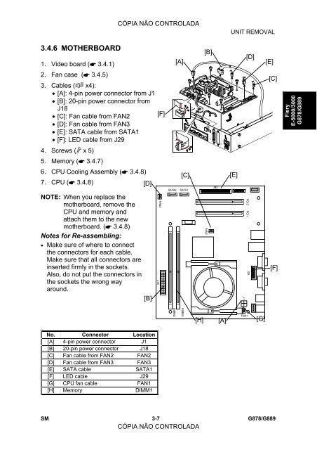
3.4.6 MOTHERBOARD<br />
1. Video board ( 3.4.1)<br />
2. Fan case ( 3.4.5)<br />
3. Cables ( x4):<br />
• [A]: 4-pin power connector from J1<br />
• [B]: 20-pin power connector from<br />
J18<br />
• [C]: Fan cable from FAN2<br />
• [D]: Fan cable from FAN3<br />
• [E]: SATA cable from SATA1<br />
• [F]: LED cable from J29<br />
4. Screws ( x 5)<br />
5. Memory ( 3.4.7)<br />
6. CPU Cooling Assembly ( 3.4.8)<br />
7. CPU ( 3.4.8)<br />
NOTE: When you replace the<br />
motherboard, remove the<br />
CPU and memory and<br />
attach them to the new<br />
motherboard. ( 3.4.8)<br />
Notes for Re-assembling:<br />
• Make sure of where to connect<br />
the connectors for each cable.<br />
Make sure that all connectors are<br />
inserted firmly in the sockets.<br />
Also, do not put the connectors in<br />
the sockets the wrong way<br />
around.<br />
No. Connector Location<br />
[A] 4-pin power connector J1<br />
[B] 20-pin power connector J18<br />
[C] Fan cable from FAN2 FAN2<br />
[D] Fan cable from FAN3 FAN3<br />
[E] SATA cable SATA1<br />
[F] LED cable J29<br />
[G] CPU fan cable FAN1<br />
[H] Memory DIMM1<br />
CÓPIA NÃO CONTROLADA<br />
[D]<br />
[B]<br />
[F]<br />
J18<br />
UNIT REMOVAL<br />
G815R010A.WMF<br />
SM 3-7<br />
CÓPIA NÃO CONTROLADA<br />
G878/G889<br />
FAN3<br />
SATA2<br />
DIMM2<br />
[A]<br />
[C]<br />
SATA1<br />
DIMM1<br />
[H]<br />
[B]<br />
FAN2<br />
JB2<br />
[A]<br />
[E]<br />
J1<br />
FAN1<br />
[D]<br />
PCI2<br />
PCI1<br />
J29<br />
[G]<br />
[E]<br />
G815R014A.WMF<br />
[C]<br />
[F]<br />
Fiery<br />
E-<strong>5000</strong>/<strong>3000</strong><br />
G878/G889