A Top-Down Verilog-A Design on the Analog-and-Digital
A Top-Down Verilog-A Design on the Analog-and-Digital
A Top-Down Verilog-A Design on the Analog-and-Digital

You also want an ePaper? Increase the reach of your titles
YUMPU automatically turns print PDFs into web optimized ePapers that Google loves.
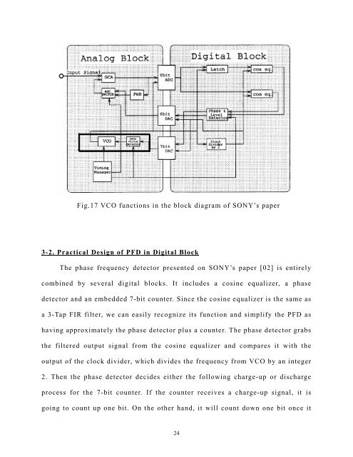
Fig.17 VCO functi<strong>on</strong>s in <strong>the</strong> block diagram of SONY’s paper<br />
3-2. Practical <str<strong>on</strong>g>Design</str<strong>on</strong>g> of PFD in <strong>Digital</strong> Block<br />
The phase frequency detector presented <strong>on</strong><br />
SONY’s paper [02] is entirely<br />
combined<br />
by several digital blocks. It includes a cosine equalizer, a phase<br />
detector <strong>and</strong> an embedded 7-bit counter. Since <strong>the</strong> cosine equalizer is <strong>the</strong> same as<br />
a 3-Tap FIR filter, we can easily recognize its functi<strong>on</strong> <strong>and</strong> simplify <strong>the</strong> PFD as<br />
having approximately <strong>the</strong> phase detector plus a counter. The phase detector grabs<br />
<strong>the</strong> filtered output signal from <strong>the</strong> cosine equalizer <strong>and</strong> compares it with <strong>the</strong><br />
output of <strong>the</strong> clock divider, which divides <strong>the</strong> frequency from VCO by an integer<br />
2. Then <strong>the</strong> phase detector decides ei<strong>the</strong>r <strong>the</strong> following charge-up or discharge<br />
process for <strong>the</strong> 7-bit counter. If <strong>the</strong> counter receives a charge-up signal, it is<br />
going to count up <strong>on</strong>e bit. On <strong>the</strong> o<strong>the</strong>r h<strong>and</strong>, it will count down <strong>on</strong>e bit <strong>on</strong>ce it<br />
24