A Top-Down Verilog-A Design on the Analog-and-Digital
A Top-Down Verilog-A Design on the Analog-and-Digital
A Top-Down Verilog-A Design on the Analog-and-Digital

Create successful ePaper yourself
Turn your PDF publications into a flip-book with our unique Google optimized e-Paper software.
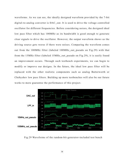
waveforms. As we can see, <strong>the</strong> ideally designed waveform provided by <strong>the</strong> 7-bit<br />
digital-to-analog c<strong>on</strong>verter is DAC_out. It is used to drive <strong>the</strong> voltage c<strong>on</strong>trolled<br />
oscillator for different frequencies. Before c<strong>on</strong>sidering noises, <strong>the</strong> designed ideal<br />
low pass filter which has 100MHz as its b<strong>and</strong>width is good enough to generate<br />
clear signals to drive <strong>the</strong> oscillator. However, <strong>the</strong> output waveform shows us <strong>the</strong><br />
driving source gets worse if <strong>the</strong>re were noises. Comparing <strong>the</strong> waveform comes<br />
out from <strong>the</strong> 100MHz filter (labeled 100MHz_out_pseudo <strong>on</strong> Fig.29) with that<br />
from <strong>the</strong> 15MHz filter (labeled 15MHz_out_pseudo <strong>on</strong> Fig.29), it is easily found<br />
an improvement occurs. Through such testbench experiments, we can begin to<br />
modify or improve our designs. In <strong>the</strong> future, <strong>the</strong> ideal low pass filter will be<br />
replaced with <strong>the</strong> o<strong>the</strong>r realistic comp<strong>on</strong>ents such as analog Butterworth or<br />
Chebyshev low pass filters. Building up more testbenches will also be our future<br />
works to more guarantee <strong>the</strong> performance of this project.<br />
DAC_out<br />
LPF_in<br />
15MHz_out_pseudo<br />
100MHz_out_pseudo<br />
Fig.29 Waveforms of <strong>the</strong> r<strong>and</strong>om-bit-generator-included test bench<br />
38