Design of High Sensitivity and Fast Response ... - COMSOL.com
Design of High Sensitivity and Fast Response ... - COMSOL.com
Design of High Sensitivity and Fast Response ... - COMSOL.com

Create successful ePaper yourself
Turn your PDF publications into a flip-book with our unique Google optimized e-Paper software.
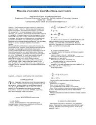
<strong>Design</strong> <strong>of</strong> <strong>High</strong> <strong>Sensitivity</strong> <strong>and</strong> <strong>Fast</strong> <strong>Response</strong> MEMS Capacitive<br />
Humidity Sensor using <strong>COMSOL</strong> Multiphysics ®<br />
R.Karthick * , Dr.SPK.Babu, AR.Abirami, S.Kalainila<br />
Department <strong>of</strong> Electronics <strong>and</strong> Communication Engineering,<br />
Periyar Maniammai University, Vallam, Thanjavur 613413<br />
Abstract: This paper presents the simulated model<br />
<strong>of</strong> capacitive humidity sensor, which predicts<br />
transient response for various humidity ranges<br />
applicable for breath analysis. The structure<br />
consists <strong>of</strong> parallel plate electrode with dielectric<br />
polymer film, simulated using <strong>COMSOL</strong><br />
Multiphysics ® based on molecular diffusion. This<br />
finite element simulation is carried out for various<br />
upper electrode structures with different type <strong>of</strong><br />
polymer for better sensitivity <strong>and</strong> response time. It<br />
is found that structure with smaller upper<br />
electrodes width (2/2 structure) provides short<br />
response time (2.5 µsecs) <strong>and</strong> structure with<br />
electrode width twice <strong>of</strong> the gap (40/20 structure)<br />
provides high sensitivity (29.96 nF /%RH).<br />
Keywords: MEMS, Capacitive Humidity<br />
sensor, <strong>COMSOL</strong>.<br />
1. Introduction<br />
A sensor is a device that converts one<br />
form <strong>of</strong> energy into another <strong>and</strong> provides the user<br />
with a usable energy output in response to a<br />
specific measurable input. For example thermister,<br />
a temperature sensor converts heat to resistance. If<br />
resistance could be read out, the temperature which<br />
has a relation to the resistance is found. The<br />
important considerations <strong>of</strong> modern sensors are low<br />
cost, small size, low power <strong>and</strong> high precision.<br />
Measuring humidity, the presence <strong>of</strong><br />
moisture in air, plays an important role in a wide<br />
<strong>and</strong> various range <strong>of</strong> practical measurement<br />
situations. Relative humidity refers to the ratio <strong>of</strong><br />
the moisture content <strong>of</strong> air to the saturation<br />
moisture level at the same temperature which is<br />
<strong>of</strong>ten needed for many applications. Humidity<br />
sensors which measures humidity range 0% to<br />
100% are widely used in Electronic chip<br />
manufacturing industry, Air conditioners, Artificial<br />
respiration units[1]. Humidity sensor is <strong>of</strong> three<br />
types, namely resistive, capacitive <strong>and</strong><br />
displacement.<br />
Modern sensor requirements can be<br />
fulfilled by Micro Electro Mechanical Systems<br />
(MEMS) technology, which was coined in the<br />
United States in the late 1980s. MEMS are made<br />
up <strong>of</strong> <strong>com</strong>ponents between 1 to 100 micrometres in<br />
size (i.e. 0.001 to 0.1 mm) <strong>and</strong> MEMS devices<br />
generally range in size from 20 micrometres (20<br />
millionths <strong>of</strong> a metre) to a millimetre. MEMS with<br />
its batch fabrication techniques enables<br />
<strong>com</strong>ponents <strong>and</strong> devices to be manufactured with<br />
increased performance <strong>and</strong> reliability, <strong>com</strong>bined<br />
with the obvious advantages <strong>of</strong> reduced physical<br />
size, volume, weight <strong>and</strong> cost[2]. MEMS based<br />
sensors are built to sense the existence <strong>and</strong> the<br />
intensity <strong>of</strong> certain physical, chemical, or<br />
biological quantities, such as pressure, force,<br />
humidity, light, temperature, nuclear radiation,<br />
magnetic flux, <strong>and</strong> chemical <strong>com</strong>position [3],[4].<br />
The MEMS based capacitive humidity<br />
sensors due to its advantages over the others are<br />
modeled earlier using the s<strong>of</strong>twares like<br />
Coventorware ® [5], MATLAB [6] <strong>and</strong> ANSYS<br />
7.0[7]. The structure was subjected to various<br />
analysis using modules in these Coventorware ® ,<br />
MATLAB <strong>and</strong> ANYSYS. Various regions <strong>of</strong><br />
operation <strong>of</strong> the sensor were notified. The resulting<br />
sensor showed promising response in these regions.<br />
The linearity <strong>of</strong> the sensor is between 10-40% RH<br />
[4] <strong>and</strong> 80% <strong>of</strong> value reached in 1 sec ANSYS<br />
7.0[7].<br />
In this paper we focus on capacitive humidity<br />
sensor based on MEMS simulated using <strong>COMSOL</strong><br />
Multiphysics ® , which is an emerging engineering<br />
s<strong>of</strong>tware environment used for modeling <strong>and</strong><br />
simulation <strong>of</strong> any physical based structure.<br />
This paper consists <strong>of</strong> five sections. Section<br />
1gives the introduction, section 2 deals about types<br />
<strong>and</strong> parameters <strong>of</strong> humidity sensor, section 3 deals<br />
with <strong>COMSOL</strong> Multiphysics ® s<strong>of</strong>tware, section 4<br />
elaborates MEMS based sensors, section 5 deals<br />
with Modeling <strong>of</strong> Humidity Sensor using<br />
<strong>COMSOL</strong> Multiphysics ® , section 6 deals with<br />
optimization <strong>of</strong> the humidity sensor for better<br />
response time <strong>and</strong> sensitivity <strong>and</strong> section 7<br />
elaborates the conclusion.<br />
2. Humidity Sensors<br />
Humidity sensors are used to senses <strong>and</strong><br />
measure the Relative Humidity (RH) for various<br />
applications. Different humidity sensors exist for<br />
miscellaneous applications. The requirements that<br />
humidity sensors must meet in order to satisfy a<br />
wide range <strong>of</strong> applications are good sentivity over a<br />
wide range, short response time, reproducibility,<br />
small hysteresis, good durability <strong>and</strong> long life,<br />
resistance against contaminant <strong>and</strong> low cost [8].<br />
Types <strong>of</strong> humidity sensors are resistive humidity<br />
sensor, displacement humidity sensor <strong>and</strong><br />
capacitive humidity sensor.<br />
Resistive humidity sensors mainly use ceramics
<strong>and</strong> polymers as humidity sensitive materials,<br />
including TiO2, LiZnVO4, MnWO4,C2O <strong>and</strong> Al2O3<br />
[9]. In general, ceramics have good chemical<br />
stability, high mechanical strength <strong>and</strong> resistance to<br />
high temperature [9]. Due to the extremely high<br />
resistance at RH values <strong>of</strong> less than 20%, this<br />
sensor is generally better suited to the higher RH<br />
ranges.<br />
Perhaps the oldest type <strong>of</strong> RH sensor still in<br />
<strong>com</strong>mon use is the displacement sensor. These<br />
devices use a strain gauge or other mechanism to<br />
measure expansion or contraction <strong>of</strong> a material in<br />
proportion to changes in relative humidity. The<br />
advantages <strong>of</strong> this type <strong>of</strong> sensor are that it is<br />
inexpensive to manufacture <strong>and</strong> highly immune to<br />
contamination. Disadvantages are a tendency to<br />
drift over time <strong>and</strong> hysteresis effects are<br />
significant.<br />
Capacitive technique is the most widely used<br />
technique for humidity sensor, where the RH<br />
change is detected by the humidity induced<br />
dielectric constant change <strong>of</strong> thin films. The most<br />
widely used materials as humidity-sensitive<br />
dielectrics are polymer films, as they provide high<br />
sensitivity, linear response, low response time <strong>and</strong><br />
low power consumption [10].<br />
Table 1: Comparison between three types <strong>of</strong> humidity<br />
sensor<br />
Parameters Capacitive Resistive Displacement<br />
RH range 0-100%<br />
possible<br />
<strong>Sensitivity</strong> <strong>High</strong> even<br />
at low RH<br />
Temperature<br />
range<br />
<strong>Response</strong><br />
time<br />
Resistive<br />
to<br />
contamination<br />
Only at<br />
higher<br />
RH range<br />
Moderate<br />
at low<br />
RH<br />
Upto 200˚c -40˚c to<br />
100˚c<br />
Fair below<br />
25%<br />
Low at low<br />
RH<br />
10˚c to<br />
100˚c<br />
<strong>Fast</strong> Moderate Moderate<br />
<strong>High</strong> due<br />
to film<br />
coating<br />
Low Low<br />
Accuracy ±2% ±2% ±4%<br />
Hysteresis Minimum Comparativ<br />
ely more<br />
more<br />
Capacitive humidity sensors are suited for high<br />
temperature environments because the temperature<br />
coefficient is low <strong>and</strong> the polymer dielectric can<br />
withst<strong>and</strong> high temperature [10].<br />
MEMS based capacitive humidity sensors<br />
are interesting because their small physical size<br />
allows them to be less intrusive. MEMS sensors<br />
have the advantage <strong>of</strong> being sensitive <strong>and</strong> accurate<br />
with minimal amount <strong>of</strong> required sample substance.<br />
These sensors are suitable for applications<br />
requiring a high degree <strong>of</strong> sensitivity at low<br />
humidity levels, where they will provide a<br />
relatively fast response [10].<br />
3. <strong>COMSOL</strong> ® : A simulation tool for MEMS<br />
<strong>COMSOL</strong> Multiphysics ® is a s<strong>of</strong>tware<br />
package which is widely used for modeling. This<br />
s<strong>of</strong>tware not only helps to define the geometry,<br />
meshing, defining physics but also helps to<br />
visualize the end results.<br />
The mathematical structure in <strong>COMSOL</strong><br />
Multiphysics ® is a system <strong>of</strong> partial differential<br />
equations. There are three ways <strong>of</strong> describing PDEs<br />
through the following mathematical application<br />
modes:<br />
1. Coefficient form, Suitable for linear or<br />
nearly linear models<br />
2. General form, suitable for non-linear models<br />
3.Weak form, for models with PDEs on<br />
boundaries, edges or points, or models using<br />
terms with mixed space <strong>and</strong> time derivatives<br />
Using these applications modes, you can<br />
perform various types <strong>of</strong> analysis including:<br />
1. Stationary <strong>and</strong> time-dependent analysis<br />
2. Linear <strong>and</strong> non-linear analysis<br />
3. Eigen frequency <strong>and</strong> modal analysis<br />
When solving the PDEs, <strong>COMSOL</strong><br />
Multiphysics ® uses the proven Finite Element<br />
Method (FEM).<br />
MEMS module is a part <strong>of</strong> the <strong>COMSOL</strong><br />
Multiphysics ® s<strong>of</strong>tware. This module helps in<br />
designing any type <strong>of</strong> MEMS device <strong>and</strong> do further<br />
analysis. The <strong>com</strong>plete details can be taken from<br />
[11].<br />
4. MEMS based humidity sensor<br />
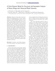
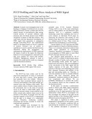
The sensor is a parallel plate capacitor with the<br />
sensitive layer. Sensitive layer is s<strong>and</strong>wich in<br />
between the electrodes. The lower electrode is a<br />
full plate, the upper electrode is a grid which<br />
allows the vapour to penetrate into the sensitive<br />
layer [12],[13].<br />
When the water vapour blows over the<br />
surface, it is adsorbed on the surface. Then the<br />
adsorbed molecule diffuse in the polymer inducing<br />
a variation <strong>of</strong> its permittivity.
Substrate Lower<br />
Electrode<br />
Figure 1. Structure <strong>of</strong> sensor<br />
Figure 2. Working principle<br />
Water<br />
vapour<br />
Variation <strong>of</strong> water vapour<br />
pressure in the air<br />
Variation <strong>of</strong> the content<br />
<strong>of</strong> water at the surface <strong>of</strong><br />
the film<br />
Variation <strong>of</strong> amount <strong>of</strong><br />
water absorbed in the<br />
film<br />
Variation <strong>of</strong> the relative<br />
permittivity <strong>of</strong> the film<br />
Capacitance variation<br />
Polymer Upper<br />
Electrode<br />
The variation in permittivity causes variation in<br />
capacitance.<br />
(1)<br />
ΔPi is the variation <strong>of</strong> water vapour partial<br />
pressure in the air. ΔCsurf is the variation <strong>of</strong> the<br />
concentration <strong>of</strong> water at the surface <strong>of</strong> the film,<br />
resulting from ΔPi. ΔQ is the variation <strong>of</strong> the<br />
amount <strong>of</strong> water adsorbed in the film (expressed in<br />
mol). Δεr is the variation <strong>of</strong> the relative permittivity<br />
<strong>of</strong> the film, <strong>and</strong> ΔГ is the capacitance variation (in<br />
pF) [14].<br />
4.1. Theoretical modeling<br />
Relative humidity is the ratio <strong>of</strong> actual vapour<br />
pressure <strong>of</strong> the air at any temperature to the<br />
maximum <strong>of</strong> saturation vapour pressure at the same<br />
temperature. Relative humidity in percent is<br />
defined as<br />
(2)<br />
Pa is the absolute vapour pressure; Ps is the<br />
saturation vapour pressure. Ps depends on<br />
temperature. By determining Ps at particular<br />
temperature, we can derive Pa for various humidity<br />
[15].<br />
4.2. Measuring saturation vapour pressure<br />
The maximum partial pressure (saturation<br />
pressure) <strong>of</strong> water vapour in air varies with<br />
temperature <strong>of</strong> the air <strong>and</strong> water vapour mixture. A<br />
variety <strong>of</strong> empirical formulas exist for this quantity;<br />
the most used reference formula is the G<strong>of</strong>f-Gratch<br />
equation for the SVP over liquid water.<br />
(3)<br />
where T, temperature <strong>of</strong> the moist air, is<br />
given in units <strong>of</strong> Kelvin <strong>and</strong> p is given in units <strong>of</strong><br />
millibars(hectopascals).<br />
4.3.Converting Pa to water vapour concentration<br />
Pa can be converted to concentration by using<br />
the formula<br />
(4)<br />
derived from PV=nRT. To get in mols/m 3 divide<br />
the equation by 18.02 which is the molecular<br />
weight <strong>of</strong> water vapour[16].<br />
Table 2: Comparison <strong>of</strong> absolute pressure <strong>and</strong> vapour<br />
condensation<br />
RH%<br />
Absolute<br />
pressure<br />
millibar<br />
Vapour<br />
concentration<br />
Mols/m 3<br />
10 6.27 0.2429<br />
20 12.55 0.4863<br />
30 18.83 0.7297<br />
40 25.11 0.9731<br />
50 31.39 1.2164<br />
60 37.67 1.4598<br />
70 43.95 1.7032<br />
80 50.23 1.9466<br />
90 56.19 2.1899<br />
100 62.79 2.4333
4.4. Diffusion modeling<br />
Diffusion <strong>of</strong> water in the film is described using<br />
Fick’s law.<br />
(4)<br />
Where c is the concentration (mols/m 3 ), t is the<br />
time(sec), D is the diffusion coefficient, x is the<br />
position. For more than one dimension<br />
(5)<br />
(6)<br />
Fick’s law predicts how diffusion causes the<br />
concentration field to change with time. It mainly<br />
depends upon diffusion coefficient [6],[17].<br />
4.5. Permittivity <strong>of</strong> sensing film<br />
The permittivity <strong>of</strong> the sensing film should be<br />
(7)<br />
Where Δεr is the variation in permittivity, εr(RH) is<br />
the permittivity after absorption, εr(0) is the<br />
permittivity before absorption. εr(RH) can be<br />
calculated from Clausius-Mossotti’s equation.<br />
(8)<br />
Where ε0 is the permittivity in free space, A is the<br />
Avogadro’s number. ΔQ derived from ΔC by<br />
integrating over the volume [18].<br />
4.6. Capacitance modeling<br />
For an unequal parallel electrode capacitor, the<br />
capacitance variation <strong>of</strong> sensor should be<br />
(9)<br />
Where ΔГ is the capacitance variation, A is the<br />
area <strong>of</strong> the upper electrode, Δεr is the variation<br />
permittivity, ε0 is the permittivity in free space, th<br />
is the thickness <strong>of</strong> the film.<br />
4.7. Geometrical modeling<br />
Parallel plates consist <strong>of</strong> upper electrode <strong>and</strong><br />
lower electrode, upper electrode in the form <strong>of</strong> grid<br />
with a sensitive layer in between which act as a<br />
dielectric.<br />
Electrode plates width is 20μm, spacing between<br />
plates is 20μm, thickness <strong>of</strong> plates is 1μm, thin film<br />
thickness is 1.5μm (DVS-BCB) [19], [20].<br />
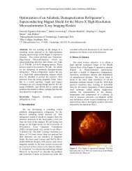
5. Results <strong>and</strong> observation<br />
5.1. Simulation <strong>of</strong> test structure<br />
A structure was modeled in <strong>COMSOL</strong><br />
Multiphysics ® . Its accuracy was checked through<br />
finite-element simulation <strong>and</strong> experiments on<br />
structure 20/20 (width <strong>of</strong> the upper electrode 20 μm<br />
<strong>and</strong> spacing between the electrodes 20 μm) with a<br />
film thickness <strong>of</strong> 1.5 μm. The electrodes are made<br />
up <strong>of</strong> aluminium <strong>of</strong> thickness 1µm <strong>and</strong> the sensitive<br />
layer is DVS – BCB in between them. The<br />
simulation was based on the assumption that<br />
diffusion in the polymer film was quit ideal<br />
because water vapour sorption in DVS – BCB<br />
follows Henry’s law, which suggests free diffusion<br />
<strong>of</strong> water molecule in film. First the structure is<br />
simulated with humidity variation from 0 to 100%<br />
to analyze transient response <strong>and</strong> sensitivity <strong>of</strong> the<br />
structure. Then the structure is modeled with<br />
different polymer sensitive layer to find the optimal<br />
sensitive layer. Finally the structure is analyzed for<br />
small humidity variation in the range <strong>of</strong> 3%. The<br />
following figure shows simulated structure in three<br />
dimensions.<br />
Figure 3. Structure in 3D<br />
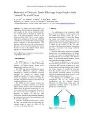
Figure 4. Simulation at time t=0.5μs<br />
Figure 5. Simulation at time t=9μs
Figure 6. Simulation at time t=45μs<br />
5.1.1 Capacitance variation with time<br />
To check the linearity <strong>of</strong> structure the<br />
test structure is simulated with humidity variation<br />
from 0 to 100 % at 26ºC, the sensor shows linear<br />
response for the variation in humidity as shown in<br />
the graph.<br />
Figure 7. Capacitance Vs Time<br />
5.1.2 Absorption <strong>and</strong> desorption<br />
The Fig 8 show the variation <strong>of</strong> capacitance with<br />
time the curve shows a transient response <strong>and</strong><br />
response time is <strong>of</strong> the order <strong>of</strong> 0.50 milisecs.<br />
Figure 8. Capacitance variation with time due to<br />
absorption<br />
Fig 9 shows the desorption <strong>of</strong> water as it is<br />
decreased from 100%RH to 0%RH. The<br />
desorption time was found to be 0.65 ms<br />
Figure 9. Capacitance variation with time due to<br />
desorption<br />
5.1.3 Structure tested with various polymer<br />
films<br />
According to sensing mechanisms, polymeric<br />
humidity sensors are divided into two fundamental<br />
categories: resistive-type <strong>and</strong> capacitive-type. The<br />
former responds to moisture variation by changing<br />
its conductivity while the latter responds to water<br />
vapour by varying its dielectric constant. Because<br />
<strong>of</strong> the excellent linear response, capacitive sensors<br />
are far more attractive than resistive sensors the<br />
change <strong>of</strong> the dielectric constant <strong>of</strong> the hygroscopic<br />
polymer is linearly proportional to the amount <strong>of</strong><br />
water absorbed. The following table gives time<br />
response <strong>com</strong>parison <strong>of</strong> different polymers used in<br />
test structure.<br />
Table 3: Comparison <strong>of</strong> response time <strong>and</strong> diffusivity <strong>of</strong><br />
test structure with different polymers.<br />
Polymers Diffusivity<br />
(µm 2 Concentration Time<br />
/s) (mols) (sec)<br />
DVS-BCB 4.5e -6 2.4374e -15 0.003<br />
PDMAA 8.7e -10 1.7340e -15 0.03<br />
PDMAEMA 10e -10 1.7783 e -15 0.03<br />
PAA 3.5 e -10 1.5023 e -15 0.03<br />
POLYVINYL<br />
acetate<br />
11 e -10 1.8103 e -15 0.03<br />
POLYMIDE 2.81 e -13 2.0850 e -16 0.03
Table 3 gives that the DVS – BCB films<br />
shows good time response <strong>and</strong> high diffusivity.<br />
This polymer is one <strong>of</strong> the lower moisture polymer<br />
<strong>and</strong> highly suitable for parallel plate capacitive<br />
humidity sensor.<br />
5.2. Optimizing for fast response time structure<br />
Simulation based on fast response model<br />
was performed to predict the behavior <strong>of</strong> different<br />
structures in order to fabricate the most optimal <strong>of</strong><br />
them. The transient response is reduced with<br />
increase in the sensing layer thickness, as<br />
theoretically expected. The minimum <strong>and</strong><br />
maximum thickness <strong>of</strong> the sensing layer is <strong>of</strong>ten<br />
limited due to the thickness <strong>of</strong> the sensing layer<br />
that can be achieved in micro fabrication. Because<br />
the thickness <strong>of</strong> the film is a limiting factor <strong>of</strong> the<br />
response time <strong>of</strong> the sensor, hence film with 1μm<br />
thickness was chosen.<br />
Another limiting phenomenon <strong>of</strong> the<br />
response time is diffusion under the upper electrode<br />
lines. A part <strong>of</strong> the surface <strong>of</strong> the film is directly<br />
exposed to moist air <strong>and</strong> the other part is covered<br />
by the upper electrode bars. Diffusion in the<br />
polymer film is bidimensional: in the exposed<br />
parts, water diffuses from the surface to the lower<br />
electrode quickly, <strong>and</strong> in the covered parts water<br />
diffuses on the sides under the upper electrode bars<br />
<strong>and</strong> diffusion rate quite limited.<br />
By reducing the size <strong>of</strong> the upper electrode,<br />
the area under covered part gets reduced <strong>and</strong> hence<br />
rate <strong>of</strong> diffusion <strong>of</strong> the water vapour in the film is<br />
increased. Thus the width <strong>of</strong> the upper electrode is<br />
the limiting factor <strong>of</strong> sensor response time. Because<br />
lines <strong>of</strong> small width provide short response times,<br />
the following structures are chosen to simulate <strong>and</strong><br />
<strong>com</strong>pare to find optimal <strong>of</strong> them: 2/2 (Figure 11),<br />
3/3 (Figure 12), 4/4 (Figure 13), <strong>and</strong> 5/5 (Figure<br />
14). Dimensions lower than 1μm were not<br />
considered because they tackle the limits <strong>of</strong> the<br />
fabrication process.<br />
Figure 11-14 shows 2D simulated in <strong>com</strong>sol ∆RH<br />
3% at 26ºc<br />
Figure 11. 2/2 Structure<br />
Figure 12. 3/3 Structure<br />
Figure 13. 4/4 Structure<br />
Figure 14. 5/5 Structure<br />
Figure15. The graph shows the response time <strong>com</strong>parison<br />
<strong>of</strong> optimized structures<br />
Four different possible <strong>com</strong>binations <strong>of</strong><br />
electrode width <strong>and</strong> gap are studied. In all the four<br />
designs the electrode width <strong>and</strong> electrode gap are<br />
equal as shown in Figure 14. These structures are<br />
simulated with variation in humidity <strong>of</strong> 3% at 26º c.<br />
The Figure 15 shows the capacitance versus time<br />
<strong>com</strong>parison <strong>of</strong> the designs, from the graph it is
clear that the response time is faster in the case <strong>of</strong><br />
structure with very small width <strong>and</strong> gap i.e. 2/2.<br />
Table.4 shows the <strong>com</strong>parison <strong>of</strong> all the<br />
four designs with their response time <strong>and</strong><br />
sensitivity, it shows that lines <strong>of</strong> small width<br />
provide short response time, but if the total surface<br />
<strong>of</strong> the upper electrode is small, the absolute<br />
capacitance <strong>of</strong> the structure is reduced.<br />
Table 4: Comparison response time<br />
Structure <strong>Response</strong><br />
time<br />
(µ secs)<br />
Desorption<br />
time<br />
(µ secs)<br />
<strong>Sensitivity</strong><br />
nf/%RH<br />
2/2 2.5 4 0.77<br />
3/3 7 8 1.15<br />
4/4 8.8 14 1.54<br />
5/5 12 18 1.92<br />
5.3. Optimizing for high sensitivity structure<br />
As the capacitance is directly<br />
proportional to the area <strong>of</strong> the upper electrode, then<br />
reducing the size (area) <strong>of</strong> electrode will reduce the<br />
capacitance i.e. sensitivity. So it is necessary to<br />
increase the size i.e. area <strong>of</strong> the upper electrode to<br />
get higher order <strong>of</strong> sensitivity.<br />
Influence <strong>of</strong> the electrode width <strong>and</strong> the<br />
gap on the sensitivity <strong>of</strong> the device was<br />
investigated. Three different possible <strong>com</strong>binations<br />
<strong>of</strong> electrode width <strong>and</strong> gap are modeled, as shown<br />
in table 5. In design- 1, the electrode width is half<br />
that <strong>of</strong> the electrode gap. In design-3, the electrode<br />
width <strong>and</strong> the electrode gap are equal. <strong>Design</strong>-2 has<br />
the electrode width twice that <strong>of</strong> the electrode gap.<br />
These three structures are subjected to a humidity<br />
variation <strong>of</strong> 3% at temperature 26ºc. The<br />
corresponding response time, desorption time <strong>and</strong><br />
sensitivity are shown in table 5:<br />
Table 5: Comparison <strong>of</strong> <strong>Sensitivity</strong><br />
Structure <strong>Response</strong><br />
time<br />
(µ secs)<br />
Desorption<br />
time<br />
(µ secs)<br />
<strong>Sensitivity</strong><br />
nf/%RH<br />
10/20 180 220 8.36<br />
40/20 250 320 29.96<br />
30/30 200 280 22.47<br />
A <strong>com</strong>parison <strong>of</strong> the sensitivities <strong>of</strong> these<br />
designs is presented in the table.5. The results show<br />
that the sensitivity is highest for the case where the<br />
electrode width is twice the electrode gap, which<br />
may be because <strong>of</strong> higher capacitance due to higher<br />
electrode area. Therefore, the proposed design will<br />
have twice electrode width than the width <strong>of</strong> the<br />
gap. The results show that the sensitivity increases<br />
with increase in the electrode width.<br />
5.4. Optimizing for sensitivity <strong>and</strong> response time<br />
Influence <strong>of</strong> the electrode width <strong>and</strong> the gap on the<br />
sensitivity <strong>and</strong> the transient response <strong>of</strong> the device<br />
are investigated. Four different possible<br />
<strong>com</strong>binations <strong>of</strong> electrode width <strong>and</strong> gap are<br />
modeled to optimization for fast response <strong>and</strong> table<br />
4. Shows the <strong>com</strong>parison <strong>of</strong> all the four designs<br />
with their response time <strong>and</strong> sensitivity, it shows<br />
that lines <strong>of</strong> small width provide short response<br />
time, but if the total surface <strong>of</strong> the upper electrode<br />
is small, the absolute capacitance <strong>of</strong> the structure is<br />
reduced.<br />
Figure 6. Comparison <strong>of</strong> sensitivity<br />
The sensitivity <strong>and</strong> response time are<br />
inversely proportional, if the structure is optimized<br />
for faster response time then the sensitivity will be<br />
decreased <strong>and</strong> vice versa. The optimization <strong>of</strong> the<br />
structure should be made by taking into account<br />
that area <strong>of</strong> the upper electrode neither maximum<br />
nor minimum <strong>com</strong>pared with the gap between the<br />
electrodes. Three models were considered for<br />
simulation with different electrode configurations<br />
(20/10, 30/15, 40/10) <strong>and</strong> <strong>com</strong>pared to get optimal<br />
<strong>of</strong> them. Three models with different<br />
configurations are simulated <strong>and</strong> the results are<br />
shown table 6. The structures with unequal upper<br />
electrode configuration show good response time<br />
with good sensitivity.
Table 6: Comparison <strong>of</strong> sensitivity <strong>and</strong> response time at<br />
26⁰C ΔRH 3%<br />
Structure <strong>Response</strong><br />
Time ms<br />
Desorption<br />
Time in ms<br />
<strong>Sensitivity</strong><br />
nf/%RH<br />
20/10 50 70 14.89<br />
30/15 120 140 22.47<br />
40/25 200 240 29.96<br />
6. Conclusion<br />
A simple <strong>and</strong> powerful model was designed for the<br />
simulation <strong>and</strong> optimization <strong>of</strong> capacitive humidity<br />
sensor. The model is supported by finite-element<br />
simulation using <strong>COMSOL</strong> Multiphysics ® , First<br />
the simulation was carried out with a test structure<br />
<strong>of</strong> film thickness <strong>of</strong> 1.5µm <strong>and</strong> with top electrodes.<br />
The structure is optimized for faster response time<br />
by varying upper electrode, smaller the upper<br />
electrode structure faster response time. Structures<br />
with configurations 2/2, 3/3, 4/4 <strong>and</strong> 5/5 were<br />
simulated <strong>and</strong> the <strong>com</strong>parison study shows that<br />
smaller electrode structure 2/2 show faster response<br />
time. Optimization is also done for higher<br />
sensitivity which shows sensitivity is higher for the<br />
structure whose upper electrode width is twice the<br />
spacing between the electrodes.<br />
7. References<br />
1. Houri Johari “Development <strong>of</strong> MEMS sensors<br />
for measurements <strong>of</strong> pressure, relative<br />
humidity, <strong>and</strong> temperature” Masters Thesis,<br />
NEST – Nano Engineering, Science, <strong>and</strong><br />
Technology, CHSLT- Center for Holographic<br />
Studies <strong>and</strong> Laser micro-mechaTronics,<br />
Mechanical Engineering Department,<br />
Worcester Polytechnic Institute, 2003.<br />
2. Jan Korvink , Oliver Paul" MEMS: A<br />
Practical Guide to <strong>Design</strong>, Analysis, <strong>and</strong><br />
Applications " William Andrew publications,<br />
United Kingdom, 2005.<br />
3. Julian W. Gardner,Vijay K. Varadan <strong>and</strong><br />
Osama O. Awadelkarim " Microsensors,<br />
MEMS <strong>and</strong> Smart Devices " Wiley, 1 edition,<br />
2001<br />
4. Dr.Thomas F.Marinis, “The Future <strong>of</strong><br />
MEMS”.<br />
5. K. Govardhan <strong>and</strong> Z.C.Alex“MEMS based<br />
Humidity Sensor” International conference on<br />
Smart Materials Structures <strong>and</strong> Systems,<br />
Bangalore, 2005.<br />
6. A. Tetelin, C. Pellet, M. de Matos, <strong>and</strong> V.<br />
Conedera, “Computer-aided response time<br />
optimization <strong>of</strong> capacitive humidity sensor,”<br />
in Proc. 3 rd IEEE Sensor Conf., Vienna,<br />
Austria, Oct. 24-27, 2004, pp. 111-114.<br />
7. A. Tetelin <strong>and</strong> C. Pellet, “Accurate model <strong>of</strong><br />
the dynamic response <strong>of</strong> a capacitive<br />
humidity sensor,” in Proc. 2 nd IEEE Sensors<br />
Conf., Toronto, ON, Canada, Oct.21-24,<br />
2003, pp. 378-383.<br />
8. Z. M. Rittersma, “Recent achievements in<br />
miniaturized humidity sensors-a review <strong>of</strong><br />
transduction techniques,” in Sensors <strong>and</strong><br />
Actuators, 2002, pp. 196-210.<br />
9. Burak Okcan <strong>and</strong> Tayfun Akin, A Low-Power<br />
Robust Humidity Sensor in a St<strong>and</strong>ard CMOS<br />
Process" IEEE TRANSACTIONS ON<br />
ELECTRON DEVICES, VOL. 54, NO. 11, pp<br />
3071-3079, NOVEMBER 2007.<br />
10. Lazarus, N.; Bedair, S.S.; Lo, C.-C.;<br />
Fedder, G.K.; "CMOS-MEMS Capacitive<br />
Humidity Sensor", Journal <strong>of</strong><br />
Microelectromechanical Systems, Volume: 19<br />
Issue:1, pp 183 - 191 , 2010<br />
11. <strong>COMSOL</strong> Multiphysics MEMS Module<br />
http://www.<strong>com</strong>sol.<strong>com</strong>/products/mems/<br />
accessed on 29.09.2011.<br />
12. U. Kang <strong>and</strong> K. D. Wise, “<strong>High</strong>-speed<br />
capacitive humidity sensor with on-chip<br />
thermal reset,” IEEE Trans. Electron Devices,<br />
Vol. 47, no. 4, pp. 702-710, 2000.<br />
13. Georgi Dobrev Kolev, Krassimir Hristov<br />
Denishev, Georgi Hrostov Dobrikov, Velichka<br />
Jordanova Strijkova <strong>and</strong> Erintche Michailova<br />
Spassova, “Humidity Microsensor with<br />
Polymide Sensitive Layer,” in Sozoplo,<br />
BULGARIA, 2008.<br />
14. J. Crank, The mathematics <strong>of</strong> diffusion,<br />
Oxford University Press, Cambridge, 1975.<br />
15. T. Kuroiwa, T. Miyagishi, A. Ito, M.<br />
Matsugushi, <strong>and</strong> Y. Sakai, “Thin-film<br />
Polysulfone-based Capacitive-type relativehumidity<br />
sensor,” Sens. Actuators B, Vol.<br />
B25, no. 1-3, pt. 2, pp. 692-695, 1995.<br />
16. Wexler, A.(ed), “Humidity <strong>and</strong> Moisture,” in<br />
Reinhold, New York, 1965, Vol.1 <strong>and</strong> 3.<br />
17. W. R. Vieth, Diffusion in <strong>and</strong> through<br />
polymers. Munich, Germany: Carl Hanser,<br />
1991.<br />
18. D. D. Denton, J. B. Camou <strong>and</strong> S. D. Senturia,<br />
“Effects <strong>of</strong> the moisture uptake on the<br />
dielectric permittivity <strong>of</strong> polymide films,”<br />
Proc. 4 th Int. Conf. Solid-State Sensors <strong>and</strong><br />
Actuators. Philadelphia, PA, Jun. 1985, ISA.<br />
19. The Dow Chemical Company, Cyclotene,<br />
available at<br />
20. H. Pranjoto <strong>and</strong> D. D. Denton, “Moisture<br />
uptake <strong>of</strong> BisBenzcyclobutene(BCB) films for<br />
electronic packaging applications,” in Mater.<br />
Res. Soc. Symp. Proc., 1991, Vol. 203, pp.<br />
295-302.