Download Paper - COMSOL.com
Download Paper - COMSOL.com
Download Paper - COMSOL.com

Create successful ePaper yourself
Turn your PDF publications into a flip-book with our unique Google optimized e-Paper software.
A Finite Element Model for Structural and Aeroelastic Analysis<br />
of Rotary Wings with Advanced Blade Geometry<br />
E. Piccione ∗ , G. Bernardini and M. Gennaretti<br />
University Roma Tre - Department of Mechanical and Industrial Engineering<br />
∗ Corresponding author:Via della Vasca Navale 79-00146 Rome, Italy, e-mail:epiccione@uniroma3.it<br />
Abstract: Objective of this paper is the development<br />
and implementation of a finite element<br />
model, in a Comsol Multyphisics context, for the<br />
prediction of the aeroelastic behavior of rotor<br />
blades. In particular, the attention is focused on<br />
new generation blades characterized by curved<br />
elastic axes, with the presence of tip sweep and<br />
anhedral angles. The blade structural model implemented<br />
is based on nonlinear flap-lag-torsion<br />
beam equations valid for slender, homogeneous,<br />
isotropic, non-uniform, twisted blades undergoing<br />
moderate displacements. Curved and arbitrarily<br />
oriented elastic axes are considered. A<br />
second-order approximation scheme for straindisplacement<br />
is adopted and inertial terms from<br />
rotating motion are included. For aeroelastic<br />
applications, aerodynamic loads are obtained<br />
from sectional theories, with inclusion of wake<br />
inflow models to take into account 3D effects. To<br />
validate the model implemented, several analyses<br />
are performed reproducing reliable results<br />
available in literature.<br />
Keywords: innovative rotor blade geometry,<br />
rotor blade dynamics, rotor blade aeroelasticity.<br />
1. Introduction<br />
Excerpt from the Proceedings of the <strong>COMSOL</strong> Conference 2010 Paris<br />
Rotary wing systems are frequently applied<br />
in aircraft. From the original application in singlerotor<br />
and tandem-rotor helicopters, nowadays<br />
they are used also in tiltrotor configurations.<br />
The main rotor plays a fundamental role in helicopter<br />
dynamics, and since early stages of the<br />
helicopter history has been carefully studied by<br />
researchers and manufacturer <strong>com</strong>panies. Particular<br />
attention has been focused on the prediction<br />
of the aeroelastic behavior of the helicopter<br />
rotor blades, which requires the application<br />
of accurate structural and aerodynamic<br />
models. Helicopter rotor blades are flexible, light,<br />
slender structures and hence the structural model<br />
has to be able to take into account both the<br />
strong coupling between bending and torsion degrees<br />
of freedom and the nonlinearities arising<br />
from the significant deformations they usually<br />
experience.<br />
One of the pioneering models for the description<br />
of the blade dynamics of pre-twisted<br />
nonuniform rotor blades was developed in Ref.<br />
[1], from a linear beam theory. Specifically, it<br />
presents the coupled equations governing in-plane<br />
bending (lag), out-of-plane bending (flap) and<br />
torsion of a twisted, rotating beam. More refined<br />
beam-like models for straight rotor blades<br />
have been developed in Refs. [2] and [3], where<br />
geometric nonlinearities are included in order to<br />
take into account moderate displacements of the<br />
blade. Aeroelastic applications of these structural<br />
models are presented in Refs. [4] and [5].<br />
Next, models for new generation rotor blades<br />
with tip sweep and anhedral angles have been<br />
developed. One of the first structural models<br />
for swept tip rotor blades has been presented in<br />
Ref. [6], as a modification of a straight blade<br />
model by including the sweep effects as chordwise<br />
offsets of the center of gravity axis with<br />
respect to the (straight) elastic axis. However,<br />
this model has been proven to be not accurate<br />
[7, 8]. A structural model for swept blade tips<br />
has been presented and succesfully applied to<br />
hingeless rotor blades in Refs. [7, 8]. A formulation<br />
for blades with varying sweep, droop,<br />
twist, and planform is given in Ref. [9]. Ormiston<br />
and Hopkins [10] developed and validated<br />
a nonlinear finite element model for swept tip<br />
rotor blades considering large deflections. It is<br />
based on the theory by Hodges and Dowell [2],<br />
introducing a reference frame at the root of each<br />
beam element that is constrained to move with<br />
the tip node of the parent beam element (updated<br />
Lagrangian formulation). In this way, a<br />
sufficient number of beam elements enable the<br />
prediction of arbitrary large displacements. An<br />
experimental-theoretical investigation on the influence<br />
of tip sweep angle on the natural frequencies<br />
of vibrations of rotor blades is available
in Ref. [11].<br />
Here, a nonlinear structural dynamic formulation<br />
suitable for analysis of blades having<br />
curved elastic axis is implemented in Comsol<br />
Multyphisics. It is an extension of the nonlinear<br />
flap-lag-torsion equations of motion presented in<br />
Ref. [2] for which each beam element is allowed<br />
to be arbitrarily oriented, thus permitting the<br />
simulation of tip sweep and anhedral angles effects.<br />
Numerical results will present a validation<br />
of the proposed Comsol Multyphisics application<br />
by <strong>com</strong>parison with experimental and<br />
numerical data available in the literature concerning<br />
free-vibration analysis of rotor blades<br />
with tip sweep and anhedral angles. In addition,<br />
coupling the structural dynamic model with a<br />
model predicting aerodynamic loads an aeroelastic<br />
formulation is developed in Comsol Multyphisics<br />
and the corresponding results are <strong>com</strong>pared<br />
with literature data. The blade dynamics<br />
model implemented in Comsol Multyphisics<br />
is open to further improvements that could be<br />
focused both on the sophistication of the implemented<br />
structural/aerodynamic formulations<br />
and on the connection of the blade with rotor<br />
hub mechanics and control chain.<br />
2. Blade structural model<br />
In this work, the nonlinear equations for homogeneous,<br />
isotropic rotor blades with straight<br />
elastic axis undergoing moderate displacements<br />
presented in Ref. [2] are used as starting point to<br />
describe the structural dynamics of rotor blades<br />
with arbitrary shape of the elastic axis. Specifically,<br />
this is achieved by writing the elastic loads<br />
in terms of local variables along the (curvilinear)<br />
elastic axis, and developing general expressions<br />
for the inertial loads due to the rotary motion<br />
of the blades. In particular, the resulting formulation<br />
is suitable for the analysis of advanced<br />
geometry blades, like those with sweep and anhedral<br />
angles at the tip.<br />
The equations implemented are obtained in<br />
a weak form, typical for finite element model,<br />
starting from Hamilton’s principle<br />
t2<br />
δI = [(δU − δT ) − δW ] dt = 0 (1)<br />
t1<br />
where U is the strain energy, T is the kinetic<br />
energy, and δW is the virtual work of the external<br />
forces. The model includes spanwise variation<br />
in mass and stiffness properties, variable<br />
built-in pretwist, precone, sweep and anhedral<br />
angle. Nonlinear strain-displacement relationship<br />
are considered: second order terms are retained<br />
in the equations after the application of<br />
an ordering scheme that drops third-order terms<br />
(with respect to bending slope) not contributing<br />
to damping [2].<br />
2.1 Variables and Coordinate Systems<br />
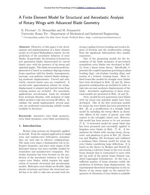
Several coordinate systems are introduced<br />
to derive the equations of motion of the blade.<br />
The main ones, given in Fig. 1, are the rotating,<br />
hub-centered orthogonal system (xR, yR, zR),<br />
the rotating, local, blade-fixed system, (x, y, z),<br />
with x axis aligned with the local undeformed<br />
elastic axis, and the rotating, local, blade-fixed<br />
system, (x ′ , y ′ , z ′ ), with x ′ axis locally aligned<br />
with the elastic axis after deformation. Each<br />
beam finite element is defined through the local<br />
coordinate system (x, y, z). Deformations are<br />
described by displacements of the elastic axis<br />
and rotations of beam sections. Displacements,<br />
u, v, w, are defined in the local frames fixed with<br />
the undeformed blade, whereas the section rotation,<br />
φ, is about the x ′ axis.<br />
z R<br />
y R<br />
u<br />
z’<br />
w<br />
v<br />
y’<br />
φ<br />
x’<br />
x<br />
z<br />
y<br />
Figure 1: Undeformed and deformed blade configurations.<br />
2.2 Strain energy contributions<br />
The first variation of the strain energy appearing<br />
in Eq. (1) is given in terms of engineering<br />
stresses and strains as follows [2]<br />
<br />
R<br />
δU =<br />
0<br />
(σxxδɛxx+σxηδɛxη +σxζδɛxζ) dη dζ dx<br />
A<br />
where R is the rotor radius, A denotes the section<br />
area, whereas η and ζ denote the principal<br />
cross section axes. Introducing the expressions<br />
for the engineering strain [2] into the equation<br />
above and assuming negligible cross-section<br />
x<br />
R
warping, the strain energy be<strong>com</strong>es<br />
R<br />
δU= Vx<br />
0<br />
′(δu′ + v ′ δv ′ + w ′ δw ′ )+(Sx ′ +Tx ′) δφ′<br />
<br />
+ Mz ′ cos ˆ θ+My ′ sin ˆ <br />
θ (δv ′′ + w ′′ δφ)<br />
<br />
+ Mz ′ sin ˆ θ−My ′ cos ˆ <br />
θ (δw ′′ − v ′′ <br />
δφ) dx (2)<br />
where ˆ θ = θ+φ, with θ denoting the blade crosssection<br />
pitch angle. In the equation above, neglecting<br />
higher order terms, stress resultants and<br />
moments are defined as [2]<br />
⎧ <br />
Vx ′ = EA u ′ + v′2 w′2<br />
+<br />
2 2 + k2 Aθ ′ φ ′<br />
<br />
⎪⎨<br />
⎪⎩<br />
Sx ′ = GJφ′<br />
Tx ′ = EAk2 A ˆ θ ′<br />
<br />
My ′ = EIy ′<br />
Mz ′ = EIz ′<br />
<br />
u ′ + v′2<br />
2<br />
<br />
w′2<br />
+<br />
2<br />
<br />
v ′′ sin ˆ θ − w ′′ cos ˆ θ<br />
<br />
v ′′ cos ˆ θ + w ′′ sin ˆ θ<br />
In the equations above, E is the Young modulus,<br />
G is the shear modulus and<br />
<br />
Iz ′ = η<br />
A<br />
2 dηdζ<br />
<br />
J =<br />
2 2<br />
η + ζ<br />
A<br />
dηdζ<br />
<br />
Iy ′ =<br />
<br />
2 2<br />
η + ζ dηdζ<br />
A<br />
ζ 2 dηdζ k 2 A = 1<br />
A<br />
Note that the blade cross sections have been assumed<br />
to be symmetric, and tensile and torque<br />
offsets have been assumed to be zero.<br />
2.3 Kinetic energy contributions<br />
The first variation of the kinetic energy appearing<br />
in Eq. (1) is given by<br />
R<br />
δT =<br />
0<br />
A<br />
A<br />
<br />
ρ V · δ V dη dζ dx<br />
where V denotes velocity of the blade points as<br />
observed by an inertial frame, and ρ is the density<br />
of the material. Expressing the blade velocity<br />
in terms of the variables introduced above,<br />
integrating by parts in time and over the blade<br />
cross section, δT be<strong>com</strong>es<br />
R <br />
δT = ( Zu<br />
¯ + ¯ Z r u) δu + ( ¯ Zv + ¯ Z r v) δv<br />
0<br />
+ ( ¯ Zw + ¯ Z r w) δw+( ¯ Zφ + ¯ Z r φ) δφ dx (3)<br />
where<br />
⎧<br />
⎪⎨<br />
⎪⎩<br />
¯Zu = −mü<br />
¯Zv = −m¨v + me ¨ φ sin θ<br />
¯Zw = −m ¨w − me ¨ φ cos θ<br />
¯Zφ = −mk2 m ¨ φ + me [¨v sin θ − ¨w cos θ]<br />
while the () r terms due to the blade rotation will<br />
be given in the next section where, for the sake<br />
of clarity, they are derived from inertial loads<br />
directly written in terms of acceleration. In the<br />
equations above, m is the mass per unit length,<br />
e is the mass offset and mk 2 m is the polar crosssection<br />
mass moment of inertia.<br />
2.4 Inertial loads due to rotary motion<br />
The expressions of the inertial loads due to<br />
the rotary motion of the blade are now obtained<br />
in the local, rotating, undeformed blade-fixed<br />
frame of reference. In order to take into account<br />
advanced blade geometry (including, for<br />
instance, tip sweep and anhedral angles), an elastic<br />
axis of arbitrary shape is considered in defining<br />
the kinematics of blade sections. The local<br />
acceleration due to blade rotation is given by<br />
a = Ω × Ω × r + 2 Ω × v<br />
where r denotes the distance of a cross section<br />
point from the hub center, v is the velocity of<br />
the same point with respect to a rotating frame<br />
fixed with the undeformed blade, while Ω is the<br />
blade angular velocity.<br />
Then, considering <strong>com</strong>ponents in the local<br />
blade-undeformed frame of reference, the resulting<br />
inertial distributed forces read<br />
<br />
<br />
px = − ρ ax dη dζ py = − ρ ay dη dζ<br />
A<br />
A<br />
<br />
pz = − ρ az dη dζ<br />
A<br />
while the resulting inertial distributed moments<br />
defined with respect to the section shear center<br />
are given by<br />
<br />
qx = ρ [ay(rz − w) − az(ry − v)] dη dζ<br />
A <br />
qy = − ρ [ax(rz − w)] dη dζ<br />
A <br />
qz = ρ [ax(ry − v)] dη dζ<br />
A
Finally, the corresponding generalized inertial<br />
loads due to blade rotation appearing in Eq.<br />
(3) are obtained from the following <strong>com</strong>bination<br />
of the distributed inertial loads [2]<br />
⎧<br />
⎪⎨<br />
⎪⎩<br />
¯Z r u = px<br />
¯Z r v = py − q ′ z<br />
¯Z r w = pz + q ′ y<br />
¯Z r φ = qx + v ′ qy + w ′ qz<br />
3. External aerodynamic loads<br />
Aeroelastic applications of the blade structural<br />
model outlined in Section 2 require the introduction<br />
of the aerodynamic loads forcing the<br />
blade dynamics. Here, for the sake of simplicity,<br />
the aerodynamic loads are derived from a quasisteady<br />
approximation of the Greenberg theory<br />
[12] for airfoils. Aerodynamic three-dimensional<br />
effects are taken into account by including a<br />
wake inflow model (see, for instance, Ref. [4]<br />
for details). Thus, section force, T , orthogonal<br />
to the chord, and section force, S, parallel to the<br />
chord are given by<br />
<br />
ϱ Clαc T = −UP UT +<br />
2<br />
c<br />
2 ω UT − c<br />
4 ˙ <br />
c<br />
<br />
2<br />
UP + ˙ω<br />
4<br />
<br />
ϱ Clαc S = U<br />
2<br />
2 P − c<br />
2 ω UP − Cd0<br />
U 2 <br />
T<br />
Clα<br />
while the section pitching moments with respect<br />
to the quarter-chord point reads<br />
<br />
ϱ Clαc3 Mφ = − ω UT −<br />
32<br />
˙ UP + 3c<br />
8 ˙ω<br />
<br />
In the equations above, UP and UT are, respectively,<br />
the quarter-chord velocity <strong>com</strong>ponents normal<br />
and parallel to the chord after deformation,<br />
ω is the section angular velocity, c denotes the<br />
chord length, ϱ is the air density, Clα is the lift<br />
slope coefficient, while Cd0 is the drag coefficient.<br />
Next, the blade aeroelastic equations are derived<br />
by expressing UP , UT and ω in terms of<br />
u, v, w and φ and expressing the aerodynamic<br />
forces given above, T and S, in terms of <strong>com</strong>ponents,<br />
Lv and Lw, in the local blade undeformed<br />
frame of reference. Indeed, in Eq. (1) they contribute<br />
to the virtual work term as follows<br />
δW = Lv δv + Lw δw + Mφ δφ (4)<br />
4. Implementation in Comsol Multiphysics<br />
The implementation in Comsol Multiphysics<br />
of both blade structural model and aerodynamic<br />
loads has been ac<strong>com</strong>plished as a modification<br />
of the 3D Euler-Bernoulli beam model present<br />
in Comsol Multiphysics 3.5a Structural Mechanics<br />
package. This choice has been motivated<br />
mainly by the following two reasons: (i) the<br />
3D Euler-Bernoulli beam model in Comsol Multiphysics<br />
has the same degrees of freedom of<br />
the rotating beam model to be implemented,<br />
and (ii) in the 3D Euler-Bernoulli finite element<br />
model transformations between global and local<br />
coordinate systems are automatically available.<br />
The model has been implemented replacing<br />
both weak and dweak terms appearing in<br />
the 3D Euler-Bernoulli beam model with those<br />
given in Eqs. (2) and (3), and defining all the<br />
parameters involved in them as global and local<br />
variables. Aerodynamic forces and moments appearing<br />
in Eq. (4) have been included as external<br />
distributed loads. The model implemented<br />
may be applied for static and dynamic solutions,<br />
as well as eigenvalue analysis.<br />
5. Results<br />
The aim of the numerical investigation is<br />
the validation of the finite element model implemented<br />
in Comsol Multiphysics in terms of<br />
both free-vibration analysis and aeroelastic response<br />
of a helicopter blade with sweep and anhedral<br />
angles at the tip (see Fig. 2). In particular,<br />
results from the present solver are <strong>com</strong>pared<br />
with numerical and experimental data available<br />
in the literature.<br />
y<br />
z<br />
R<br />
R<br />
BLADE ROOT<br />
Figure 2: Blade tip sweep, ΛS, and anhedral, ΛA,<br />
angles.<br />
Λ<br />
Λ<br />
S<br />
A<br />
x<br />
x<br />
R<br />
R
5.1 In vacuo analyses<br />
First, free-vibration, in-vacuo, analyses for<br />
the hingeless rotor blade model described in Ref.<br />
[10] are presented. Figures 3-5 show <strong>com</strong>parisons<br />
between present results and both numerical<br />
and experimental data given in Refs. [10]<br />
and [11], respectively. Specifically, Fig. 3 concerns<br />
the frequencies of vibration of the unswept<br />
rotating blade as functions of the rotating speed,<br />
Fig. 4 depicts the frequencies of vibration of<br />
the nonrotating blade for several values of the<br />
tip sweep angle (starting from the 85% of the<br />
blade span), while Fig. 5 shows the effects of<br />
the tip sweep angle on the frequencies of vibration<br />
of the rotating blade (note that, nondimensional<br />
frequencies and normalized rotation<br />
speed are related to the nominal blade rotating<br />
speed). For all the analyses presented the<br />
agreement of the present results with those from<br />
Refs. [10] and [11] is excellent, thus demonstrating<br />
the capability of the implemented finite element<br />
solver to capture the effects of rotation and<br />
curved elastic axis on free vibration of flap-lagtorsion<br />
beams. For instance, in the presence of<br />
swept tip, flap-torsion coupling is expected. Although<br />
not presented here, this behavior is correctly<br />
predicted by the present solver as revealed<br />
by observation of the predicted eigenvectors. In<br />
addition, also the significant effect of tip sweep<br />
angle on the torsional frequency experimentally<br />
observed for rotating blades (see Fig. 5) is well<br />
captured by the solver implemented in Comsol<br />
Multiphysics. These effects are a <strong>com</strong>bination of<br />
centrifugal stiffening of ‘tennis-racket’ type with<br />
torsion first-mode inertia increase.<br />
Nondimensional eigenfrequencies<br />
25<br />
20<br />
15<br />
10<br />
5<br />
0<br />
Ref. [11] - Flap<br />
Ref. [11] - Torsion<br />
Ref. [10]<br />
Present results<br />
0 0.2 0.4 0.6 0.8 1<br />
Normalized rotational speed<br />
Figure 3: Normalized eigenfrequencies vs normalized<br />
rotor speed. Unswept blade.<br />
Nondimensional eigenfrequencies<br />
25<br />
20<br />
15<br />
10<br />
5<br />
0<br />
Ref. [11] - Flap<br />
Ref. [11] - Torsion<br />
Ref. [10]<br />
Present results<br />
0 5 10 15 20 25 30 35 40 45<br />
Sweep angle [deg]<br />
Figure 4: Normalized eigenfrequencies vs sweep<br />
angle. Nonrotating blade.<br />
Nondimensional eigenfrequencies<br />
25<br />
20<br />
15<br />
10<br />
5<br />
0<br />
Ref. [11] - Flap<br />
Ref. [11] - Torsion<br />
Ref. [10]<br />
Present results<br />
0 5 10 15 20 25 30 35 40 45<br />
Sweep angle [deg]<br />
Figure 5: Normalized eigenfrequencies vs sweep<br />
angle. Rotating blade.<br />
5.2 Aeroelastic analyses<br />
Next some aeroelastic analyses for hovering<br />
configurations are presented for hingeless, straight<br />
rotor blades, as well as for hingeless rotor<br />
blades with tip sweep and anhedral angles.<br />
First the untwisted, stiff-in-plane blade with<br />
straight elastic axis described in Ref. [4] is considered.<br />
Figure 6 depicts the steady-state deflections<br />
(flap-lag displacements and torsion rotation)<br />
at the tip of the blade, predicted for several<br />
values of the blade pitch angle. In addition,<br />
Figs. 7 and 8 present the results of the<br />
perturbation aeroelastic eigenanalysis (in terms<br />
of eigenfrequencies and dampings, respectively)<br />
carried out about the trim configuration of Fig.<br />
6. Figures 6-8 show an excellent agreement between<br />
present results and those given in Refs. [4]
and [13] for the same rotor configurations, thus<br />
validating, for a straight blade, the formulation<br />
implemented in Comsol Multiphysics. These results<br />
demonstrate that the inclusion of aerodynamic<br />
effects introduces dampings in the blade<br />
dynamic behavior that are strongly dependent<br />
on the blade pitch (both directly and via the stationary<br />
trim configuration that is perturbed).<br />
Nondimensional tip displacements and rotations<br />
Nondimensional eigenfrequencies<br />
0.1<br />
0.08<br />
0.06<br />
0.04<br />
0.02<br />
0<br />
-0.02<br />
Ref. [4]<br />
Ref. [13]<br />
Present model<br />
Flap<br />
-0.04<br />
0 0.05 0.1 0.15 0.2 0.25 0.3<br />
Collective pith angle [rad]<br />
Torsion<br />
Lag<br />
Figure 6: Equilibrium blade tip deflections.<br />
5<br />
4.5<br />
4<br />
3.5<br />
3<br />
2.5<br />
2<br />
1.5<br />
1<br />
Ref. [4]<br />
Ref. [13]<br />
Present model<br />
0.5<br />
0 0.05 0.1 0.15 0.2 0.25 0.3 0.35 0.4 0.45<br />
collective pith angle [rad]<br />
Torsion<br />
Lag<br />
Flap<br />
Figure 7: Aeroelastic eigenfrequencies for straight<br />
blade.<br />
Then, the blade described in Ref. [13] is<br />
considered for the analysis on the aeroelastic<br />
stability effects due to tip sweep and anhedral<br />
angles. In particular, the tip 10% of the blade is<br />
subject to sweep and anhedral distortion. Figures<br />
9 and 10 present the results of the aeroelastic<br />
eigenanalysis for the baseline blade given<br />
in Ref. [13] for several values of the sweep angle,<br />
respectively in terms of eigenfrequencies and<br />
Nondimensional dampings<br />
0<br />
-0.05<br />
-0.1<br />
-0.15<br />
-0.2<br />
-0.25<br />
-0.3<br />
-0.35<br />
Ref. [4]<br />
Ref. [13]<br />
Present model<br />
-0.4<br />
-0.05 0 0.05 0.1 0.15 0.2 0.25 0.3 0.35 0.4 0.45<br />
Collective pith angle [rad]<br />
Lag<br />
Flap<br />
Torsion<br />
Figure 8: Aeroelastic dampings for straight blade.<br />
dampings. Next, Figs. 11 and 12 show the<br />
same kind of results concerning a modified blade<br />
where structural data have been tailored so as<br />
to cause a strong coupling between first-torsion<br />
and second-flap modes. The <strong>com</strong>parison between<br />
the results presentd in Ref. [13] and those from<br />
the formulation implemented in Comsol Multiphysics<br />
reveals a very good agreement. In particular,<br />
the present approach is able to predict<br />
both the different influence the sweep angle has<br />
on the depicted modes and the instabilizing effects<br />
induced by the frequency coalescence appearing<br />
in the modified blade (see Figs. 11 and<br />
12).<br />
Nondimensional eigenfrequencies<br />
10<br />
8<br />
6<br />
4<br />
2<br />
Ref. [13]<br />
Present results: 1st lag 1st flap 3rd flap<br />
2nd lag 2nd flap 1st torsion<br />
0<br />
0 5 10 15 20 25 30 35 40<br />
Sweep angle [deg]<br />
Figure 9: Aeroelastic eigenfrequencies vs sweep angle.<br />
Baseline blade.<br />
Finally, the effects of anhedral angle on blade<br />
aeroelastic behavior has been investigated. Figures<br />
13 and 14 show the results of the aeroelastic<br />
eigenanalysis for the baseline blade given
Nondimensional dampings<br />
0<br />
-0.05<br />
-0.1<br />
-0.15<br />
-0.2<br />
-0.25<br />
-0.3<br />
-0.35<br />
Ref. [13]<br />
Present results: 1st lag 1st flap 3rd flap<br />
2nd lag 2nd flap 1st torsion<br />
-0.4<br />
0 5 10 15 20 25 30 35 40<br />
Sweep angle [deg]<br />
Figure 10: Aeroelastic dampings vs sweep angle.<br />
Baseline blade.<br />
Nondimensional eigenfrequencies<br />
8<br />
7<br />
6<br />
5<br />
4<br />
3<br />
2<br />
1<br />
Ref. [13]<br />
Present results: 1st lag 1st flap 3rd flap<br />
2nd lag 2nd flap 1st torsion<br />
0<br />
0 5 10 15 20 25 30 35 40<br />
Sweep angle [deg]<br />
Figure 11: Aeroelastic eigenfrequencies vs sweep<br />
angle. Modified blade.<br />
Nondimensional dampings<br />
0.2<br />
0<br />
-0.2<br />
-0.4<br />
-0.6<br />
Ref. [13]<br />
Present results: 1st lag 1st flap 3rd flap<br />
2nd lag 2nd flap 1st torsion<br />
0 5 10 15 20 25 30 35 40<br />
Sweep angle [deg]<br />
Figure 12: Aeroelastic dampings vs sweep angle.<br />
Modified blade.<br />
Nondimensional eigenfrequencies<br />
8<br />
7<br />
6<br />
5<br />
4<br />
3<br />
2<br />
1<br />
Ref. [13]<br />
Present results: 1st lag 1st flap 3rd flap<br />
2nd lag 2nd flap 1st torsion<br />
0<br />
-20 -15 -10 -5 0 5 10 15 20<br />
Anhedral angle [deg]<br />
Figure 13: Aeroelastic eigenfrequencies vs anhedral<br />
angle. Baseline blade.<br />
Nondimensional dampings<br />
0<br />
-0.05<br />
-0.1<br />
-0.15<br />
-0.2<br />
-0.25<br />
-0.3<br />
-0.35<br />
Ref. [13]<br />
Present results: 1st lag 1st flap 3rd flap<br />
2nd lag 2nd flap 1st torsion<br />
-0.4<br />
-20 -15 -10 -5 0 5 10 15 20<br />
Anhedral angle [deg]<br />
Figure 14: Aeroelastic dampings vs anhedral angle.<br />
Baseline blade.<br />
Nondimensional eigenfrequencies<br />
8<br />
7<br />
6<br />
5<br />
4<br />
3<br />
2<br />
1<br />
Ref. [13]<br />
Present results: 1st lag 1st flap 3rd flap<br />
2nd lag 2nd flap 1st torsion<br />
0<br />
-20 -15 -10 -5 0 5 10 15 20<br />
Anhedral angle [deg]<br />
Figure 15: Aeroelastic eigenfrequencies vs anhedral<br />
angle. Modified blade.
Nondimensional dampings<br />
0.1<br />
0<br />
-0.1<br />
-0.2<br />
-0.3<br />
Ref. [13]<br />
Present results: 1st lag 1st flap 3rd flap<br />
2nd lag 2nd flap 1st torsion<br />
-0.4<br />
-20 -15 -10 -5 0 5 10 15 20<br />
Anhedral angle [deg]<br />
Figure 16: Aeroelastic dampings vs anhedral angle.<br />
Modified blade.<br />
in Ref. [13], for several values of the anhedral<br />
angle, while Figs. 15 and 16 present the results<br />
of the same analysis concerning a modified<br />
balde model in which structural properties have<br />
been set to get the frequency coalescence between<br />
first-torsion and second-lag modes. Akin<br />
to the <strong>com</strong>parison presented for the sweep variation,<br />
the <strong>com</strong>parison between present results<br />
and those in Ref. [13] is quite good. The influence<br />
of anhedral angle on aeroelastic damping is<br />
well captured, as well as the instabilizing effects<br />
induced by the frequency coalescence appearing<br />
in the modified blade (see Figs. 15 and 16).<br />
6. Conclusions<br />
A nonlinear formulation for the structural<br />
and aeroelastic analysis of rotating blades with<br />
advanced geometry (nonuniform, twisted blades<br />
with curved elastic axis) has been implemented<br />
in the finite-element Structural Mechanics module<br />
of Comsol Multiphysics. It has been validated<br />
for both in-vacuo free-vibration analyses<br />
and hovering aeroelastic eigenanalyses, by <strong>com</strong>parison<br />
with experimental data and numerical<br />
results available in the literature. Both freevibration<br />
and aeroelastic results have shown the<br />
capability of the formulation to predict with good<br />
accuracy the structural dynamics and aeroelastic<br />
behavior of rotating blades. In particular,<br />
structural coupling effects and influence of tip<br />
sweep and anhedral angles on aeroelastic damping<br />
have been shown to be correctly predicted.<br />
This validate the implemented blade model that<br />
seem to be a reliable tool for application in anal-<br />
ysis and design of helicopter rotor blades and<br />
tiltrotor proprotors. Further developments include<br />
(from the structural point of view) the extension<br />
to non-isotropic blades and (from the<br />
aeroelastic point of view) the extension to forward<br />
flight configurations.<br />
7. References<br />
1. J.C. Houbolt and G.W. Brooks, Differential<br />
Equations of Motion for Combined Flapwise<br />
Bending, Chordwise Bending, and Torsion<br />
of Twisted Nonuinform Rotor Blades,<br />
NACA Report 1346 (1958)<br />
2. D.H. Hodges and E.H. Dowell, Nonlinear<br />
Equations of Motion for the Elastic Bending<br />
and Torsion of Twisted Nonuniform Rotor<br />
Blades, NASA TN D-7818 (1974)<br />
3. A. Rosen and P.P. Friedmann, The Nonlinear<br />
Behavior of Elastic Slender Straight<br />
Beams Undergoing Small Strains and Moderate<br />
Rotations, Journal of Applied Mechanics,<br />
46(1), 161-168 (1979)<br />
4. D.H. Hodges and R.A. Ormiston, Stability<br />
of Elastic Bending and Torsion of Uniform<br />
Cantilever Rotor Blades in Hover with<br />
Variable Structural Coupling, NASA TN D-<br />
8192 (1976)<br />
5. J. Shamie and P.P. Friedmann, Effect of<br />
Moderate Deflections on the Aeroelastic<br />
Stability of a Rotor Blade in Forward Flight,<br />
Procedings of 3rd European Rotorcraft and<br />
Powered Lift Aircraft Forum, 24.1-24.37<br />
(1977)<br />
6. F.J. Tarzanin Jr. and R.R. Vlaminck, Investigation<br />
of the Effect of Blade Sweep on<br />
Rotor Vibratory Loads, NASA-CR-166526<br />
(1983)<br />
7. R. Celi and P.P. Friedmann, Aeroelastic<br />
Modeling of Swept Tip Rotor Blades Using<br />
Finite Elements, Journal of the American<br />
Helicopter Society, 33(2), 43-52 (1988)<br />
8. R. Celi, Aeroelasticity and Structural Optimization<br />
of Helicopter Rotor Blades with<br />
Swept Tips, PhD Dissertation, Mechanical,<br />
Aerospace and Nuclear Engineering Department,<br />
University of California, Los Angeles<br />
(1987)<br />
9. G.S. Bir and I. Chopra, Aeromechanical<br />
Stability of Rotorcraft with Advanced Geometry<br />
Blades, Mathematical and Computer
Modeling, 19(314), 159-191 (1994)<br />
10. A.S. Hopkins and R.A. Ormiston, An Examination<br />
of Selected Problems in Rotor<br />
Blade Structural Mechanics and Dynamics,<br />
Proceedings American Helicopter Society<br />
59th Annual Forum (2003)<br />
11. J.J. Epps and R. Chandra, The Natural<br />
Frequencies of Rotating Composite Beams<br />
With Tip Sweep, Journal of the American<br />
Helicopter Society, 41(1), 29-36 (1996)<br />
12. J.M. Greenberg, Airfoil in Sinusoidal Motion<br />
in Pulsating Stream, NACA - TN 1326<br />
(1947)<br />
13. K.A. Yuan and P.P. Friedmann, Aeroelasticity<br />
and Structural Optimization of Composite<br />
Helicopter Rotor Blades With Swept<br />
Tips, NASA CR-4665 (1995)