Download Paper - COMSOL.com
Download Paper - COMSOL.com
Download Paper - COMSOL.com

Create successful ePaper yourself
Turn your PDF publications into a flip-book with our unique Google optimized e-Paper software.
PCCP Profiling and Tube Wave Analysis of WRE Signal<br />
N.M. Alam Chowdhury *,1 , Zaiyi Liao 2 and Lian Zhao 1<br />
1 Dept of Electrical & Computer Engineering, Ryerson University<br />
2 Dept of Architectural Science, Ryerson University<br />
*350 Victoria Street, Toronto, ON, M5B 2K3, m9chowdh@ryerson.ca<br />
Abstract: Acoustic wave propagation due to the<br />
breakage or slippage of reinforced wire in waterfilled<br />
prestressed concrete cylinder pipe (PCCP)<br />
attracts interest in non-destructive pipe testing.<br />
Current practice of acoustic emission (AE)<br />
detection and wire-break related events (WRE)<br />
recognition is based on field data analysis. This<br />
work deals with the theoretical investigation of<br />
WRE signal from generation to propagation<br />
through water-filled PCCP. The mathematical<br />
model is developed based on Navier’s equation<br />
of motion. Newton’s law of motion in<br />
equilibrium is used to consider the fluid-structure<br />
interaction during the propagation. To<br />
understand the characteristics of WRE signal and<br />
the impact of path on the signal, the dispersion<br />
behavior of wave propagation is analyzed by the<br />
tube wave analysis for various pipe profiles.<br />
<strong>COMSOL</strong> Multiphysics software is used to<br />
simulate this model and the results are <strong>com</strong>pared<br />
with the theoretical solutions.<br />
Keywords: PCCP Profile, Pipe stiffness,<br />
Acoustic emission, WRE signal, Tube waves.<br />
1. Introduction<br />
Excerpt from the Proceedings of the <strong>COMSOL</strong> Conference 2008 Boston<br />
The PCCP has been widely used for the<br />
large-scale transmission of water or wastewater<br />
for more than half a century. These pipelines<br />
have generally been very reliable. However,<br />
there have been occasional failures caused by<br />
corrosion and breakage of the high-strength prestressed<br />
wires that reinforce these pipes. This<br />
causes sudden release of elastic energy stored in<br />
the prestressed wire in the form of acoustic<br />
waves [1-4] which is called WRE signal. The<br />
release of acoustic energy would continue as the<br />
defect extends and as plastic strains occur in the<br />
presence of the defect. If enough wires fail, the<br />
structural capacity of the PCCP is <strong>com</strong>promised<br />
and the pipe is in danger of a catastrophic<br />
rupture. Therefore, conducting condition<br />
assessment has be<strong>com</strong>e essential to ensure the<br />
continued safe operations.<br />
Many methods were developed for the<br />
detection of WRE signal and to locate the<br />
corroded areas [5-16]. Acoustic Emission<br />
Testing (AET) is one of the main technologies<br />
used in related industry for non-destructive pipe<br />
detection. AET is a continuous condition<br />
monitoring system that establishes the level of<br />
active distress in individual PCCP pipes by<br />
measuring the frequency and number of wire<br />
related events that occur over a specified range<br />
in a defined period of time. These events are<br />
captured using hydrophones or accelerometers.<br />
Current practise of AET detection and WRE<br />
signal recognition is based on field data analysis.<br />
There is no systematic theoretical analysis from<br />
WRE signal generation to propagation.<br />
Therefore, theoretical investigation of acoustic<br />
wave propagation of WRE signal in water-filled<br />
PCCP is the main interest of our work.<br />
The vibration signal generated by AE of<br />
WRE in PCCP is related to deterioration passes<br />
through a number of media, such as pipes, water<br />
and surrounding media, before the signal is<br />
picked up by the sensors. This wave propagation<br />
is the convolution of the WRE signal and the<br />
impulse response of the pipe. The impulse<br />
response of the pipe varies depending upon water<br />
flow, diameter, thickness and stiffness of the<br />
pipe and surrounding media, etc. Therefore, to<br />
solve this problem we have to consider different<br />
physics and their interaction during the<br />
propagation. Analytical solution of this model is<br />
very <strong>com</strong>plicated and difficult. We use<br />
<strong>COMSOL</strong> Multiphysics to simulate this model.<br />
The simulation results are then <strong>com</strong>pared with<br />
the theoretical results.<br />
In this paper, we develop a mathematical<br />
model to observe this WRE signal propagation<br />
through water-filled PCCP. The physical<br />
mechanism of an AE signal generation from wire<br />
deterioration within PCCP is investigated. We<br />
also investigate the impacts of the path on the<br />
spectral profiles of the vibrating WRE signal in<br />
different locations throughout the PCCP.<br />
This paper is organized as follows. The<br />
mathematical formulation of the model is given<br />
in Section 2. The boundary conditions that are<br />
used during the simulation are given in Section<br />
3. The problem description is presented in
Section 4. The use of <strong>COMSOL</strong> software to<br />
simulate the model and the results are given in<br />
Section 5. Finally in Section 6, concluding<br />
remarks and future extension of this work are<br />
presented.<br />
2. Mathematical Formulation<br />
The WRE signal generated by a wire break<br />
or slippage would propagate through the pipe<br />
structure and the water in the pipe. The PCCP<br />
structure mainly consists of concrete and steel<br />
<strong>com</strong>ponent which are highly attenuative<br />
<strong>com</strong>pared to the water inside the pipe. Therefore,<br />
for typical AE levels, the WRE signal that<br />
transmitted to the water column can be detected<br />
for several hundreds of feet, on contrary, in the<br />
pipe structure it can travel only 100 feet [17].<br />
However, for the sake of <strong>com</strong>putational brevity,<br />
the analysis will be done assuming that the WRE<br />
signal starts to propagate from fluid-pipe<br />
interface surface through fluid column only,<br />
which then interacts with the pipe wall.<br />
Navier’s equation of motion is used to model<br />
this propagation. For a homogeneous isotropic<br />
elastic medium, the equation is [18]<br />
u<br />
u u , (1)<br />
∂t<br />
2<br />
2<br />
μ + ( λ+ μ) ( ) ρ 2<br />
∂<br />
∇ ∇ ∇⋅ =<br />
where u is the displacement vector, μ and λ are<br />
the Lame constants and ρ is the density.<br />
The vector u can be de<strong>com</strong>posed into scalar<br />
φ and vector ψ velocity potential which satisfy<br />
the following wave equations [19-20]<br />
1<br />
∂ φ<br />
2<br />
∇ φ − 2<br />
vL<br />
2<br />
2<br />
∂t<br />
=<br />
2<br />
2<br />
1 ∂ ψ<br />
2<br />
vS<br />
2<br />
∂t<br />
0,<br />
(2)<br />
∇ ψ − = 0,<br />
(3)<br />
where vL and S represents the longitudinal (L)<br />
and shear (S) wave velocities of the medium,<br />
respectively. The waves in the water can be<br />
characterized by the L-wave only [21], whereas,<br />
in the pipe structure both L- and S-wave must be<br />
solved entirely [19].<br />
v<br />
The AE source which generates these waves<br />
is the elastic energy that is released from the<br />
breakage or slippage of the prestressed wire.<br />
Considering this source [22] and using pressurevelocity<br />
relation in Eq.(2), the pressure wave in<br />
water can be written as<br />
2<br />
1 ∂ p ⎛ 1 ⎞<br />
+ ∇⋅ p g,<br />
2 2 ⎜−∇ ⎟=<br />
ρWvW ∂t ⎝ ρW<br />
⎠<br />
(4)<br />
where g is the source, ρW is the water density<br />
and vW<br />
is the speed of WRE signal in the water.<br />
The WRE signal which propagated through<br />
water column appears as acoustic wave pressure<br />
on the pipe wall of the water-pipe interface and<br />
generates consistent displacements and<br />
deformations [23]. Since the pipe structure is<br />
much stiffer than the fluid, therefore, it will<br />
interact without causing separation or voids,<br />
which means that the radial displacements and<br />
pressure at the fluid-structure interfaces must be<br />
<strong>com</strong>patible and in equilibrium. In equilibrium<br />
condition, the total work done in the pipe<br />
structure due to these displacements and<br />
deformations is equal to the work from external<br />
pressure forces. Newton’s law of motion in<br />
equilibrium is used to model this fluid-structure<br />
interaction.<br />
The acoustic pressure force that acts on the<br />
pipe structure can be written as [24]<br />
F = −n<br />
.<br />
(5)<br />
W W p<br />
To satisfy the Newton’s second law of<br />
motion, the work inside the pipe structure is<br />
calculated using the normal acceleration of the<br />
pipe surface at the fluid domain boundary as<br />
a = −n ⋅∇u.<br />
(6)<br />
Here nW and nP represents the outwardpointing<br />
unit normal vector seen from inside the<br />
pipe and acoustic domain, respectively and ( ΄ )<br />
represents the time derivative of displacement<br />
vector in three principal directions.<br />
P P ′<br />
2.1 Tube Waves<br />
The plane wave propagation of WRE signal<br />
through water-filled PCCP is affected by the<br />
characteristic of pipe profile. This characteristic<br />
mainly depends on the thickness and elastic
properties of the pipe materials and the<br />
surrounding medium. The elastic wave generated<br />
in the pipe structure depends on these<br />
characteristics, which then propagating into the<br />
fluid and decreases the velocity of acoustic wave<br />
of WRE signal. This reduced wave is known as<br />
‘Tube Wave’. The impact of the path on loworder<br />
mode WRE signal propagation can be<br />
illustrated by using this tube wave analysis.<br />
Mathematically, tube wave is expressed<br />
as[25]<br />
v<br />
T<br />
where,<br />
⎡ 1 ρ ⎤ W = ⎢ + 2 ⎥<br />
⎣vW MP⎦<br />
−12<br />
,<br />
−1<br />
(7)<br />
2<br />
⎡<br />
D ⎤<br />
MP = EP<br />
⎢21<br />
( + γ P)<br />
+ ⎥ , (8)<br />
⎣ t( D+ t)<br />
⎦<br />
and D is the diameter of the pipe, P E , γ and t P<br />
are the elastic (Young’s) modulus, thickness and<br />
poisson’s ratio of the pipe materials and<br />
surrounding medium, respectively.<br />
3. Boundary Conditions<br />
The boundary conditions that apply to<br />
simulate this model are as follows:<br />
a. continuity of pressure,<br />
b. continuity of acceleration, and<br />
c. radiation condition.<br />
The boundary condition, continuity of<br />
pressure is used to represent the acoustic<br />
pressure forces in the fluid to the pipe structure.<br />
The continuity of acceleration is used to apply<br />
the normal acceleration in the pipe surface to the<br />
fluid boundary.<br />
The radiation boundary condition is used on<br />
the outer perimeter of the model. For the outward<br />
travelling wave, this boundary condition<br />
provides minimal or no reflections from the<br />
model boundary.<br />
4. Problem Description<br />
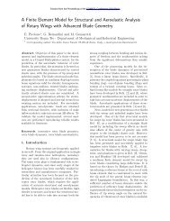
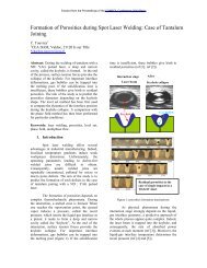
Consider a uniform and smooth circular<br />
shape water-filled pipe surrounded by the soil<br />
medium. For simplicity assume that the pipe is<br />
made of high-strength concrete only. Damping<br />
and fluid-flow velocity are absent here. The base<br />
dimensions and properties of the medium are<br />
given in Figure 1 and Table-1, respectively.<br />
y<br />
z<br />
x<br />
Soil<br />
Figure 1: Model geometry with dimensions.<br />
Table-1: Properties of the medium.<br />
Properties Water Concrete Soil<br />
Density of medium<br />
(ρ), kg/m 3<br />
Speed of acoustic<br />
wave (v), m/s<br />
Elastic(Young's)<br />
modulus (E), Pa<br />
Water<br />
Sourc<br />
Outer Boundary<br />
250m<br />
1.5m<br />
PCCP<br />
0.1m<br />
1m<br />
997 2400 1270<br />
1500 -- 463<br />
-- 40 9 --<br />
Poisson's ratio (γ) -- 0.33 --<br />
5. Simulation Results Using <strong>COMSOL</strong><br />
The finite element based software <strong>COMSOL</strong><br />
Multiphysics is used to simulate the WRE signal<br />
propagation through PCCP. The transient<br />
analysis of mathematical model outlined above is<br />
applied in two scenarios, water-filled pipe in air<br />
medium and in soil medium. The ‘solid, stressstrain’<br />
and ‘pressure acoustic’ modes of<br />
<strong>COMSOL</strong>’s acoustics module are used for this<br />
purpose [24]. The acoustic pressure in the water<br />
domain at the surface of the structure is<br />
considered as a boundary load on the solid pipe<br />
structure to ensure the continuity of pressure.<br />
The harmonic stresses and strains inside the solid<br />
structure are calculated using the normal<br />
acceleration of the solid surface at the acoustic<br />
domain to ensure the continuity in acceleration.<br />
Outer boundaries of the model are truncated by<br />
using radiation boundary condition with the<br />
cylindrical and plane wave propagation.<br />
During the simulation, we use different<br />
dimensions and stiffness of the layered medium.<br />
This exemplifies the effect of pipe profiling on<br />
tube mode propagation of WRE signal through<br />
water-filled PCCP. All simulations are done for
the 200Hz excitation frequency as this frequency<br />
is below the first cut-off frequency of the pipe<br />
used here [26]. The constant volume velocity<br />
source [27] with 1e-2 m 3 /s flow strength is used<br />
to optimize the result. The time response of the<br />
system is taken at selected points in the pipe (at<br />
0m, 50m, 100m, 150m, 200m from source).<br />
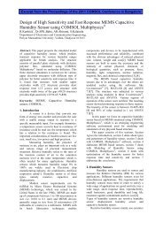
In Figures 2 and 3, the pipe is considered in<br />
air-medium with base dimensions and properties<br />
(as given in Fig.1 and Tab.1). The elastic<br />
properties ( E ) of the pipe are varies in Figure<br />
P<br />
2, as 20GPa, 30GPa, 40GPa with densities ( ρ ) P<br />
as 2200 kg/m 3 , 2300 kg/m 3 , 2400 kg/m 3 ,<br />
respectively, to verify the effect of pipe materials<br />
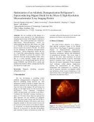
on WRE signal. In Figure 3, pipe thickness (tp)<br />
varies as 0.15m and 0.2m by keeping all other<br />
parameters constant to observe the effect of pipe<br />
thickness on wave propagation.<br />
(a) EP = 20GPa (calculated vT<br />
= 0.98 km/s).<br />
(b) EP = 30GPa (calculated vT<br />
= 1.09 km/s).<br />
(c) EP = 40GPa (calculated vT<br />
= 1.16 km/s).<br />
Figure 2: Tube wave response at different E . P<br />
(a) tp = 0.15m (calculated vT<br />
= 1.24 km/s).<br />
(b) tp = 0.2m (calculated vT<br />
= 1.28 km/s).<br />
Figure 3: Tube wave response at different tp.
From the figures above, it is seen that the<br />
propagation speed is reduced to a lower speed<br />
due to the tube wave effect [26], <strong>com</strong>pared to the<br />
speed of the acoustic wave in water (approx.<br />
1.5km/s). The calculated theoretical vT which is<br />
given below in each graph, is matched with the<br />
simulation results. It also seen that the<br />
increasing of the pipe elasticity and thickness,<br />
increases the stiffness of the pipe, and leaser its<br />
influence on wave speed and strength.<br />
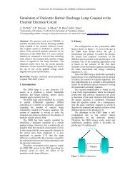
In Figure 4, consider the water-filled pipe is<br />
surrounded by different kinds of soil medium. In<br />
this work, we are mainly interested to know in<br />
what extent soil properties affect the WRE signal<br />
propagation. Therefore, we chose three kinds of<br />
soil sample, Adrian, Catlin and Plainfield soil<br />
[28] to cover the wide range of soil elastic<br />
properties (Table-2). All other parameters (as in<br />
Fig.1 and Tab.1) are kept as constants.<br />
(a) Adrian soil (calculated vT<br />
= 1.169 km/s).<br />
(b) Catlin soil (calculated v<br />
= 1.170 km/s).<br />
T<br />
(c) Plainfield soil (calculated vT<br />
= 1.172 km/s).<br />
Figure 4: Tube wave response at different soil.<br />
Table-2: Properties of the soil sample [29].<br />
Soil Series<br />
(Code)<br />
Density,<br />
kg/m 3<br />
Propagation<br />
Speed, m/s<br />
Adrian (ADA) 920 373<br />
Catlin (CAB) 1270 463<br />
Plainfield (PLA) 1510 634<br />
In the graphs above, we found that the<br />
simulation results have a good agreement with<br />
the calculated theoretical vT<br />
. However, if we<br />
<strong>com</strong>pare these results with the result of same<br />
pipe in air medium (Fig.2c), we can see<br />
that, vT<br />
values are the nearly same in all cases. It<br />
is possible, because the stiffness of the PCCP is<br />
much higher than the soil medium. Therefore, it<br />
is seen that the tube wave propagation of PCCP<br />
does not get affected by the surrounding soil<br />
formation.<br />
6. Conclusions<br />
It is observed that the speed of acoustic<br />
waves traveling in the fluid surrounded by the<br />
finite stiffness pipe profile is lower than the<br />
actual speed of waves in the unbounded fluid or<br />
fluid surrounded by infinite stiffness medium.<br />
The stiffness of the pipe increases with the<br />
increasing elastic properties of pipe materials<br />
and pipe thickness which increases the tube wave<br />
speed.
In contrast to the soil properties the pipe<br />
profile, which depends on the pipe materials and<br />
thickness that play an important role on the<br />
overall system stiffness. Therefore, in case of<br />
high stiffness pipe profile, there is no need for<br />
more attention in the estimation of accurate soil<br />
parameters. Moreover, from the results, it is<br />
observed that the high stiffness pipe can reduce<br />
signal energy penetration. This is important<br />
information for the sensor sensitivity when the<br />
WRE signal is measured far away from the<br />
source. In this paper we verified our simulation<br />
results with the theoretical calculated values. We<br />
can also verify these results with the experiment<br />
to validate our analysis.<br />
7. Acknowledgement<br />
This work has been supported by the Ontario<br />
Centres of Excellence (OCE) under Grant No.<br />
EE50196.<br />
8. References<br />
1. M. Dingus, J. Haven, R. Austin,<br />
Nondestructive, noninvasive assessment of<br />
underground pipelines, Denver: Amer.<br />
Water Works Assn. (2002).<br />
2. American Society for the Testing of<br />
Materials. Standard definitions of terms<br />
relating to acoustic emission, STM E610-82<br />
(1982).<br />
3. M. Weaver, “Fundamentals in acoustic<br />
emission,” Proc. 22 nd European Conf. on<br />
Acous. Emission Testing, Aberdeen, UK<br />
(1996).<br />
4. O. Tozser, J. Elliott, “Continuous acoustic<br />
monitoring of prestressed structures,”<br />
Proc. CSCE Struct. Specialty Conf. (2000).<br />
5. A.W. Peabody, "Control of pipeline<br />
corrosion", National Association of<br />
Corrosion Engineers, Houston (1967).<br />
6. R.E. Price, and M.B. Brooks, "Evaluation<br />
of concrete pressure pipelines and<br />
prevention of failures", Proc. Am. Soc. of<br />
Civil Engineers Annual Convention, San<br />
Diego, California (1995).<br />
7. F.A. Travers, "Acoustic monitoring of<br />
prestressed concrete pipe", Constr.<br />
Building Mater., vol. 11, no. 3, pp. 175-187<br />
(1997).<br />
8. J. Makar, "Evaluation of acoustic<br />
monitoring for prestressed concrete<br />
cylinder pipe", NRC Report B-5103.1,<br />
National Research Council, Ottawa,<br />
Ontario (1998).<br />
9. D. O'Day, "External corrosion in<br />
distribution systems", J. Am. Water Works<br />
Association, pp. 45-52 (1969).<br />
10. R. Wirahadikusumah, D.M. Abraham, T.<br />
Iseley, and R.K. Prasanth, "Assessment<br />
technologies for sewer system<br />
rehabilitation", Automation in Constr., vol.<br />
7, no. 4, pp. 259-270 (1998).<br />
11. G. Phetteplace, "Infrared thermography for<br />
condition assessment of buried district<br />
heating piping", Trans. ASHRAE, vol. 105,<br />
part 2, pp. 776-781 (1999).<br />
12. B. Mergelas, "Personal <strong>com</strong>munication",<br />
Pressure Pipe Inspection, Mississauga,<br />
Ontario (1998).<br />
13. D. Sack, and L. Olson, "In site<br />
nondestructive testing of buried precast<br />
concrete pipe", Proc. of the Am. Soc. of<br />
Civil Engineers, Mater. Engineering Conf.,<br />
Sand Diego (1994).<br />
14. N. Krstulovic Opara, R.D. Woods, N. Al<br />
Shayea, "Nondestructive testing of concrete<br />
structures using the rayleigh wave<br />
dispersion method", J. Am. Concrete<br />
Institute Mater., vol. 93, no. 1, pp. 75-86<br />
(1996).<br />
15. J.M. Makar, and N. Chagnon, "Inspecting<br />
systems for leaks, pits, and corrosion", J.<br />
Am.Water Works Assoc., vol. 91, no. 7, pp.<br />
36-46 (1999).<br />
16. R. Bernstein, M. Oristaglio, D.E. Miller,<br />
and J. Haldorsen, "Imaging radar maps<br />
underground objects", Computer<br />
Applications in Power, vol. 13, no. 3, pp.<br />
20-24 (2000).<br />
17. F.B. Stulen and J.F. Kiefner, "Evaluation of<br />
acoustic emission monitoring of buried<br />
pipelines", Proc. IEEE Ultra. Symp., pp.<br />
898-903 (1982).<br />
18. J. N. Barshinger, J. L. Rose and M. J.<br />
Avioli, “Guided wave resonance tuning for<br />
pipe inspection,” J. Pressure Vessel Tech.,<br />
vol. 124, pp. 303-310 (2002).<br />
19. D.C. Gazis, “Three-dimensional<br />
investigation of the propagation of waves in<br />
hollow circular cylinders : I - Analytical<br />
foundation,” J. Acoust. Soc. Am., vol. 31,<br />
no. 5, pp. 568-573 (1959).
20. J.D. Achenbach, Wave Propagation in<br />
Elastic Materials, NHPC (1973).<br />
21. V.N. Rama Rao and J.K. Vandiver,<br />
“Acoustics of fluid-filled boreholes with<br />
pipe: Guided propagation and radiation,” J.<br />
Acoust. Soc. Am., vol. 105, no. 6, pp. 3057-<br />
3066 (1999).<br />
22. Y.Z. Pappas, A. Kontsos, T.H. Loutas and<br />
V. Kostopoulos, “On the characterization of<br />
continuous fibers fracture by quantifying<br />
acoustic emission and acousto-ultrasonics<br />
waveforms,” Elsevier: NDT & E. Int., vol.<br />
37, no. 5, pp. 389-401 (2004).<br />
23. B. Torby, Energy Methods, Advanced<br />
Dynamics for Engineers, HRW Series in<br />
Mechanical Engineering, CBS College<br />
Publishing, USA (1984).<br />
24. <strong>COMSOL</strong> 3.4: Acoustics Module - User’s<br />
Guide, Comsol User Doc., <strong>COMSOL</strong> AB,<br />
Stockholm (2007).<br />
25. P.M. Morse and H. Feshbach, Methods of<br />
Theoretical Physics-II, McGraw-Hill, NY<br />
(1953).<br />
26. J.E. White, Underground Sound:<br />
Application of Seismic Waves, Elsevier<br />
Science, NY (1983).<br />
27. H. Y. Lee, Drillstring Axial Vibration and<br />
Wave Propagation in Boreholes, Ph.D.<br />
thesis, MIT, Cambridge, MA, USA (1991).<br />
28. F. Adamo, G. Andria, F. Attivissimo and N.<br />
Giaquinto, “An acoustic method for soil<br />
moisture measurement,” IEEE Trans.<br />
Instrum. Meas., vol. 53, no. 4, pp. 891-898<br />
(2004).<br />
29. M.L. Oelze, W.D. O’Brien and R.G.<br />
Darmody, “Measurement of attenuation and<br />
speed of sound in soils,” J. Soil Sci. Soc.<br />
Am., vol. 66, pp. 788-796 (2002).