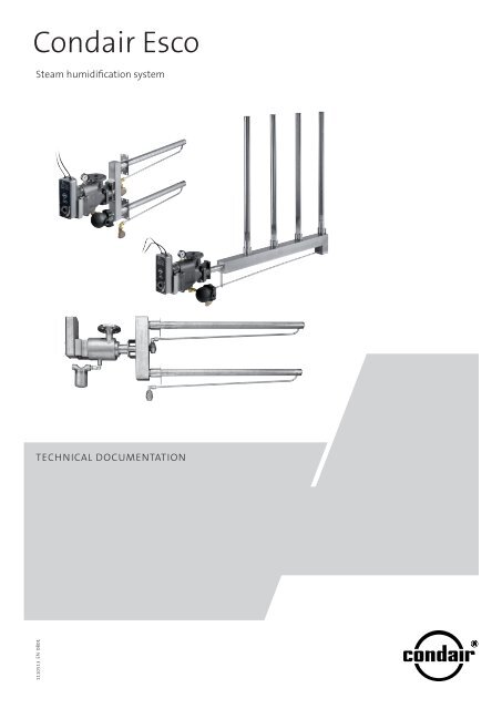
Condair Esco
Condair Esco
Condair Esco
Create successful ePaper yourself
Turn your PDF publications into a flip-book with our unique Google optimized e-Paper software.
<strong>Esco</strong><br />
Steam humidification system<br />
TEChNiCal DoCumENTaTioN<br />
1110513 EN 0801 <strong>Condair</strong>
Possible applications for the <strong>Condair</strong> <strong>Esco</strong> live steam humidification system<br />
Why humidify with steam?<br />
Using steam to humidify the air...<br />
In the proximity of machinery and production processes, optimal<br />
air humidity is essential. Of course for hospitals, as well<br />
as clinics, laboratories, and the chemical and pharmaceutical<br />
industries, air humidity and hygiene is an absolute necessity.<br />
In storage rooms, where organic matter like fish, vegetables<br />
or tobacco is kept for longer periods of time, optimal air humidity<br />
will prevent undesired drying and preserve the freshness.<br />
It improves the health and well-being of people, animals and<br />
plants, especially during the heating season. <strong>Condair</strong> <strong>Esco</strong>’s<br />
steam air humidification system satisfies these requirements<br />
to a high degree.<br />
To humidify the air with water vapour is the most direct, simplest,<br />
and safest method. Humidity contained in air is called<br />
water vapour. To humidify the air means increasing its water<br />
vapour content. The <strong>Condair</strong> <strong>Esco</strong> steam humidification system<br />
raises the lacking humidity to the proper, optimal value without<br />
any undesired side-effects.<br />
• is indisputably the most hygienic method (sterile)<br />
• causes no disturbing odours<br />
• hardly affects the temperature of the air (isothermal)<br />
• prevents waterborne mineral deposits from accumulating in<br />
air ducts and rooms<br />
• allows optimal control of the air humidity<br />
• requires minimal maintenance
Contents<br />
1 Important notes 6<br />
1.1 Correct use for intended purpose 6<br />
1.2 Safety instructions 7<br />
1.3 Notes on the technical documentation 8<br />
1.4 Warranty/liability 8<br />
2 The Humidifier 9<br />
2.1 Steam humidification system <strong>Condair</strong> <strong>Esco</strong> 9<br />
2.2 System <strong>Condair</strong> <strong>Esco</strong> 5 10<br />
2.3 System <strong>Condair</strong> <strong>Esco</strong> 10, 20 and 30 13<br />
2.4 Function 14<br />
2.5 Connection unit 15<br />
3 Humidifier selection 17<br />
3.1 The essentials in brief 17<br />
3.2 Connection unit and ceramic rotary-disk control valve 19<br />
3.3 Rotary control valve actuator 20<br />
3.4 Steam distribution 24<br />
3.6 Manometer 28<br />
3.7 <strong>Condair</strong> <strong>Esco</strong> stainless steel 29<br />
4 Hints for the consulting engineer and the HVAC technician 34<br />
4.1 The use of steam in air humidification 34<br />
4.2 Installation instructions 35<br />
4.3 Using the humidification distance diagrams 35<br />
4.4 Installation in systems or ducts 41<br />
4.5 Dimension diagrams 43<br />
4.6 Dimensions diagrams for installation 45<br />
4.7 Connection diagrams for actuators 48<br />
5 Hints for the heating engineer 50<br />
5.1 Connecting the steam supply pipe 50<br />
5.2 Installing the steam pipes 50<br />
5.3 Schematic diagram 54<br />
5.4 Connections to be prepared by customer 55<br />
6 Initial start-up 56<br />
7 Maintenance 57<br />
8 Trouble-shouting guide 58<br />
9 Vaporisation / condensation 59<br />
9.1 Terminology and definitions 59<br />
10 Work sheet DR 73 / DL 40 61
1 Important notes<br />
1.1 Correct use for intended purpose<br />
Please read this chapter carefully. It contains important information,<br />
which must be observed for safe, correct, and economic operation of<br />
the steam humidification system <strong>Condair</strong> <strong>Esco</strong>.<br />
Steam humidification systems <strong>Condair</strong> <strong>Esco</strong> are intended exclusively for<br />
indirect humidification via steam distribution pipe in a ventilation duct. For<br />
applications in process technology systems, please consult the supplier. Any<br />
other type of application is considered as not conforming with the intended<br />
purpose. The supplier cannot be made liable for any damage resulting<br />
from improper use. The user bears full responsibility.<br />
Correct use for intended purpose further includes:<br />
• Observation of the instructions, regulations and notes contained in the<br />
present technical documentation for the steam humidification system<br />
<strong>Condair</strong> <strong>Esco</strong>.<br />
• This technical documentation contains all information required for<br />
planning a humidification project which utilises the steam humidification<br />
system <strong>Condair</strong> <strong>Esco</strong>. In addition, it contains all information necessary<br />
to install such a system.<br />
• The technical documentation is intended for use by engineers, planning<br />
personnel and system constructors entrusted with the design of<br />
humidification systems. It is assumed, that these persons have a good<br />
understanding of the ventilation and humidification technology.<br />
• The steam humidification system <strong>Condair</strong> <strong>Esco</strong> incorporates the latest<br />
technical advances and meets all recognised safety regulations<br />
(manufacturer’s statement). Ignorance of appliance-specific qualities or<br />
improper use, however, can result in danger to the user or third parties<br />
and/or impairment of the system and other material values.<br />
• The notes in the technical documentation concerning the planning /layout<br />
of a humidification system, and the installation details for the steam<br />
humidification system <strong>Condair</strong> <strong>Esco</strong> must be observed and followed<br />
without fail.
1.2 Safety instructions<br />
The following points must be observed in addition to this technical documentation:<br />
• All local safety regulations concerning the use of pressurised steam<br />
systems.<br />
• All local safety regulations concerning the use of mains-supplied electrical<br />
equipment.<br />
• All instructions and warnings in the publications for the products used<br />
in conjunction with the steam humidification system <strong>Condair</strong> <strong>Esco</strong>.<br />
• All safety regulations concerning the system in which the steam humidification<br />
system <strong>Condair</strong> <strong>Esco</strong> is fitted.<br />
• All instructions and warnings provided on the steam humidification<br />
system <strong>Condair</strong> <strong>Esco</strong>.<br />
• All local sanitary regulations.<br />
The well organised world-wide <strong>Condair</strong> distributor network provides service<br />
at all times by qualified technicians. Please contact your supplier if you have<br />
any queries concerning the steam humidification system <strong>Condair</strong> <strong>Esco</strong> or<br />
humidification technology in general.<br />
• The steam humidification system <strong>Condair</strong> <strong>Esco</strong> must only be installed,<br />
operated and serviced by persons familiar with this product and sufficiently<br />
qualified for the task. The customer must ensure that the technical<br />
documentation is supplemented by internal instructions with respect<br />
to supervisory and notification liability, work organisation, personnel<br />
qualification, etc.<br />
• Persons unfamiliar with the operating instructions must neither operate<br />
nor service the steam humidification system <strong>Condair</strong> <strong>Esco</strong>. The user<br />
of this steam humidification system is responsible for preventing any<br />
unauthorised persons from operating this humidifier.<br />
• Without proper qualifications, no operations may be carried out for which<br />
the consequences are not known. In case of doubt, the supervisor or<br />
the supplier must be contacted.<br />
• Original <strong>Condair</strong> accessories and options from your supplier must<br />
be used exclusively for installation of the steam humidification system<br />
<strong>Condair</strong> <strong>Esco</strong>.<br />
• Without the written consent of the supplier, no attachments or modifications<br />
must be made to steam humidification systems <strong>Condair</strong> <strong>Esco</strong>,<br />
accessories, and options.<br />
• Original <strong>Condair</strong> spare parts from your supplier must be used exclusively<br />
for service and maintenance of the steam humidification system <strong>Condair</strong><br />
<strong>Esco</strong>.<br />
• Do not remove the flanges from the steam connection units.
1.3 Notes on the technical documentation<br />
1.4 Warranty/liability<br />
Limitation<br />
Comments in the present technical documentation “Steam Humidification<br />
System <strong>Condair</strong> <strong>Esco</strong>” are limited to details:<br />
• on the proper planning of systems<br />
• on the proper installation<br />
• on the proper commissioning procedure<br />
• on the proper operation and maintenance<br />
• on service and trouble-shooting<br />
Safekeeping<br />
Keep this technical documentation in a safe place where it is always<br />
available. If applicable, it must be passed on to subsequent users. If this<br />
documentation is misplaced, please contact your supplier.<br />
Language versions<br />
Contact your supplier if you require another language version of your<br />
technical documentation.<br />
Warranty entitlements expire, and no liability is assumed for damages<br />
caused by:<br />
• improper installation or application contrary to the intended purpose<br />
• installation of modifications which were not approved by <strong>Condair</strong><br />
• improper maintenance by unqualified personnel<br />
• using spare parts and accessories other than original <strong>Condair</strong> ones
2 The Humidifier<br />
2.1 Steam humidification system <strong>Condair</strong> <strong>Esco</strong><br />
Wherever existing steam is employed for humidification, the steam humidification<br />
systems <strong>Condair</strong> <strong>Esco</strong>, DR 73 and DL 49, prove to be outstanding.<br />
The precisely controlled steam mass flow is evenly distributed into<br />
the air current, void of any condensate spray. Steam humidification<br />
systems <strong>Condair</strong> <strong>Esco</strong>, type DR 73 and DL 40 operate very reliably. They<br />
are compact, easily installed, and thanks to computerised layout, permit<br />
a system-optimised humidification distance. The absolutely steam-tight<br />
rotary-disk control valve prevents temperature energy losses in the<br />
closed position.<br />
• Safe operation<br />
Strainers, water separators, as well as primary and secondary condensate<br />
drains ensure clean, condensate-free steam. The nozzles, tapping<br />
the steam at the centre of the distribution pipe, render the jacket<br />
heating unnecessary, because accumulating condensate is drained via<br />
secondary steam trap.<br />
• Compact<br />
Strainer, water separator, steam trap, rotary-disk control valve and rotary<br />
actuator form a compact unit, requiring little space.<br />
• Easy to install<br />
Combining all important parts into one compact unit, averts the need<br />
for expensive additional installations and prevents sealing problems<br />
during installation.
2.2 System <strong>Condair</strong> <strong>Esco</strong> 5<br />
10<br />
Small, compact valve-unit with integrated ceramic rotary-disk valve and<br />
mounted steam connection flange. 1/2"-female thread for the steam supply<br />
pipe. Designed for the connection to DL40 standard single-steam distributors<br />
5/023 - 5/178.<br />
Technical specifications:<br />
Max. steam capacity 127 kg/hr (with p1 = 4 bar)<br />
Valve admission pressure p1 0.2...4.0 bar<br />
Valve-sizes 5/1...5/7<br />
Accessory:<br />
Primary, thermostatic steam trap including 1/2"-connection fitting; execution<br />
complete stainless steel. The thermostatic steam trap immediately adjusts<br />
to changing operation terms and it deaerates automatically. Condensate is<br />
removed with a supercooling of 4 K.<br />
Actuators:<br />
The following actuators can be mounted:<br />
1) electrical rotary disk actuators CA75, CA150, CA150-S<br />
2) pneumatic actuator type P10<br />
Options:<br />
• Strainer, delivered loose (installation recommended)<br />
• Mounting set for insulated ducts<br />
• Adaptors for the mounting of other electrical rotary actuators<br />
• Positioner XSP31 with mounting kit to pneumatic actuator P10
Steam distribution pipes DL 0-<strong>Esco</strong><br />
Type Duct width mm m D kg/hr<br />
5/023 275 - 424 16<br />
5/038 425 - 524 27<br />
5/048 525 - 624 32<br />
5/058 625 - 724 41<br />
5/068 725 - 924 50<br />
5/088 925 - 1224 62<br />
5/118 1225 - 1524 94<br />
5/148 1525 - 1824 118<br />
5/178 1825 - 2124 127<br />
Valve size diagram <strong>Condair</strong> <strong>Esco</strong> 5<br />
Valve admission pressure p1 [bar]<br />
2.2.1 Material specifications <strong>Condair</strong> <strong>Esco</strong> 5<br />
Version Standard<br />
Valve-body, flange GGG40<br />
Valve-disks SIC<br />
Drive shaft 1.4305 (AISI 304)<br />
Live spindle CuZn<br />
Compression spring 1.4401 (AISI 316L)<br />
Flat packing PTFE<br />
O-ring seals EPDM/PTFE<br />
Fittings galvanised steel<br />
Tooth-and locking plates 1.4110<br />
Double nipple for primary steam trap 1.4404 (AISI 316L)<br />
Primary steam trap, thermal 1.4301<br />
Strainer SF12:<br />
Steam capacity m D [kg]<br />
Diagram for determining the dimension of the <strong>Esco</strong> steam connection unit with appropriate<br />
valve size.<br />
Housing GGG40<br />
Screen 1.4301 (AISI 304)<br />
11
2.2.2 Dimension diagram <strong>Condair</strong> <strong>Esco</strong> 5 steam connection unit,<br />
rotary disc actuator CA 150 / CA 150-S<br />
2.2.3 Dimension diagram <strong>Condair</strong> <strong>Esco</strong> 5 steam connection unit,<br />
rotary disc actuator CA 75<br />
12<br />
100<br />
100<br />
A<br />
A<br />
ø45<br />
ø45<br />
106<br />
106<br />
264<br />
268<br />
G 1/2"<br />
G 1/2"<br />
G 1/2"<br />
G 1/2"<br />
143<br />
143<br />
50 198<br />
160<br />
50 116<br />
160<br />
45°<br />
ø84<br />
ø84<br />
ø41<br />
ø8.5<br />
ø41<br />
45°ø8.5
2.3 System <strong>Condair</strong> <strong>Esco</strong> 10, 20 and 30<br />
6<br />
1 Steam connection<br />
2 Strainer<br />
3 Water separator<br />
4 Primary condensate drain connection<br />
5 Ceramic rotary-disk control valve<br />
6 Rotary actuator<br />
Complete steam connection unit with rotary disk actuator and water separator<br />
for humidifiers type DR73 and DL40.<br />
1<br />
2 3<br />
4<br />
5<br />
7<br />
DR 73<br />
7 Connecting flange<br />
8 Secondary condensate drain<br />
9 Steam nozzles<br />
10 Steam distribution pipe<br />
11 Main distribution pipe<br />
12 Condensate return line<br />
Type DR 73 and DL 40, of the steam humidification system <strong>Condair</strong> <strong>Esco</strong>,<br />
blow precisely controlled, dried steam, uniformly into the air current, void<br />
of any condensate spray.<br />
Steam distribution takes place via steam distribution pipes with integrated<br />
nozzles. The nozzles, tapping the steam at the centre of the distribution pipe,<br />
render the jacket heating unnecessary, because accumulating condensate<br />
is drained via secondary steam trap. Operational reliability and compact,<br />
easy-to-install design characterise this steam humidification system.<br />
10<br />
DL40<br />
9<br />
8<br />
8<br />
9<br />
11 12<br />
10 12<br />
13
2.4 Function<br />
1<br />
On the inlet side, the steam humidification systems <strong>Condair</strong> <strong>Esco</strong> DR 73 and<br />
DL 40 are connected to the live steam supply. The steam on hand, when<br />
the ceramic rotary-disk control valve is closed, is continuously drained by<br />
means of the primary condensate drain (spheric float) float). Thus, the humidifier<br />
is operable any time. The steam distributor, however, remains cold and<br />
does not heat the air current; no energy is wasted.<br />
With the ceramic rotary-disk control valve open, the steam passes through<br />
the strainer into the water separator. As a result of the multiple steam deflection<br />
in the water separator, the condensate, carried along, is reliably<br />
eliminated and drained via primary condensate drain.<br />
In the DR 73 type, the dried steam exits the water separator through the<br />
ceramic rotary-disk control valve to flow via main distribution pipe into the<br />
vertically arranged secondary pipes. The hot, dry steam is tapped at the<br />
centre of the steam distribution pipes and discharged under pressure on<br />
both sides, by means of special nozzles, at an angle to the air current.<br />
Condensate, accumulating in the vertical pipes, slides along the inside of<br />
the pipe down into the horizontally attached main distribution pipe (= collector).<br />
This spaciously designed pipe is drained by way of an externally<br />
mounted thermal secondary condensate drain.<br />
In the DL 40 type, the steam is directly routed into the steam distribution<br />
pipe, tapped at the centre of it and discharged under pressure, by means of<br />
special nozzles, into or against the air current. Condensate, accumulating<br />
along the inside of the pipe, is drained via condensate return line by way of<br />
an externally mounted thermal secondary condensate drain.<br />
Any condensate accumulating during system start-up is immediately drained<br />
by the primary steam trap. The pre-dried steam is led via control valve into<br />
the distribution system, where it is taken from the dry center of the pipe<br />
and introduced uniformly into the volume flow by means of the differential<br />
pressure. Thanks to this dependable system, there is no need for a start-up<br />
protection and jacket heating.<br />
Condensate-related backpressure is an impossibility in both lines of products<br />
even in a pressureless state, because the steam distributor pipe is<br />
drained via condensate return line with inherent down gradient.
2.5 Connection unit<br />
• Steam connection<br />
Connection to the steam supply is made from the top by means of a<br />
standard flange.<br />
• Strainer<br />
The strainer is located inside the connection unit at an angle of 90<br />
degrees to the steam inlet. Its unique design results in a uniform flow<br />
of steam, at a significantly reduced velocity, through the entire screen<br />
area into the water separator. If required, the threaded connection<br />
facilitates cleaning the screen.<br />
• Water separator<br />
The water separator removes the condensate droplets carried along<br />
by the steam entering through the strainer. The droplets slide down the<br />
inner wall of the water separator into the primary condensate drain. The<br />
dried steam flows to the ceramic rotary-disk control valve.<br />
• Steam trap<br />
The steam humidification systems <strong>Condair</strong> <strong>Esco</strong> DR 73 and DL 40 both<br />
utilise a primary and a secondary condensate drain. The primary<br />
condensate drain consists of a spheric float that adapts to pressure<br />
and capacity fluctuations and continuously drains the condensate from<br />
the steam connection unit (alternatively a drain with a bell-shaped float<br />
may be used instead).<br />
The secondary condensate drain empties the condensate accumulating<br />
in the steam distribution pipes. This thermal steam trap is maintenancefree.<br />
1
1<br />
• Ceramic rotary-disk control valve<br />
The humidifier control valve consists of two SiC (silicon carbide) ceramic<br />
disks, pressing against each other. One of them is fixed, while the other<br />
one is rotating. It is distinguished by the following features:<br />
• Compact design: The control valve is integrated into the connection<br />
unit.<br />
• Tightness: With the ceramic rotary-disk control valve closed, no<br />
steam can pass into the humidification section. Thus, the tightly sealing<br />
valve prevents undesired formation of condensate and damage,<br />
caused by off-periods (corrosion etc.).<br />
• Beyond the opening point of the valve the characteristic curve of<br />
the control valve is linear for the entire regulating range.<br />
• Rotary control valve actuators: One standardised rotary control<br />
valve actuator with emergency function for all valve bodies. A second<br />
rotary actuator (without emergency function) is available for low-capacity<br />
humidifiers.<br />
Specifications:<br />
Standard Version<br />
Primary steam pressure range PN6 connection unit: 0.2....4.0 bar<br />
(Pressure values are generally expressed in bar overpressure)<br />
Max. primary steam temperature: 152 °C<br />
Leak rate of SiC ceramic rotary-disk control valve: 0.0001%<br />
GGG 40 Valve body/water separator/flange<br />
SIC Ceramic rotary-disk control valve<br />
1.4301 (AISI 304) Strainer<br />
GG20 (T90-20/T90-30)<br />
1.4301 (T90-10)<br />
Filter cover<br />
CuAl10Ni5Fe4 Stuffing box<br />
1.4305 Valve stem<br />
CuZn (T90-10/T90-20)<br />
1.4305 (T90-30)<br />
Valve catch<br />
1.4401 (AISI 316L) Compression spring<br />
PTFE Flat-packing<br />
CuZn Bearing<br />
CuZn Threaded joint for primary condensate drain<br />
GGG 40 Primary condensate drain (spheric float drain)<br />
EPDM / PTFE-FEP O-ring seals<br />
CuZn Manometer<br />
GGG 40 Coupling piece to actuator<br />
1.4301 Complete steam distribution system DR 73 and DL 40<br />
1.4305 Steam nozzles
3 Humidifier selection<br />
3.1 The essentials in brief<br />
When tendering or ordering, it should be noted that the steam humidification<br />
system <strong>Condair</strong> <strong>Esco</strong>, type DR 73 and DL 40 consists of the following<br />
components (*=optional):<br />
1. Connection unit<br />
2. Ceramic rotary-disk control valve<br />
3. Rotary control valve actuator<br />
4. Steam distribution system<br />
5. Mounting set for insulated ducts*<br />
6. Manometer*<br />
7. Coupling piece for multiple piping*<br />
Operating range for steam humidification systems <strong>Condair</strong> <strong>Esco</strong>, type<br />
DR 73 and DL 40:<br />
Primary steam pressure (for live steam): 0,2...4,0 bar<br />
Primary steam temperature: 104...152 °C<br />
Max. ambient temperature: 50 °C<br />
Max. ambient humidity: 98 % r.h.<br />
Text for tendering<br />
Steam humidification system <strong>Condair</strong> <strong>Esco</strong><br />
Steam humidifier for connection to an existing steam supply, consisting of:<br />
• Connection unit with flanged connection, steam-tight ceramic rotary-disk control valve, strainer, separation chamber and<br />
primary spheric float steam trap<br />
• Steam distribution pipe, with steam nozzles, for a uniform discharge of live steam into air current throughout the entire<br />
length of the pipe, and thermal secondary condensate drain<br />
• Electric rotary actuator for connection to all commercially available humidity controllers<br />
Type DR 73<br />
Steam humidification system consisting of: connection unit, electric<br />
rotary actuator, horizontal main distribution pipe with condensate<br />
drain pipe, and vertically arranged secondary pipes with steam<br />
nozzles.<br />
Humidification capacity: ....................... kg/hr<br />
Primary steam overpressure: ....................... bar<br />
Humidity inlet/outlet: ....................... g/kg<br />
Air volume: ....................... m 3/hr<br />
Brand <strong>Condair</strong> <strong>Esco</strong><br />
Type .......................<br />
Supplier .......................<br />
Accessories, optional<br />
• Manometer mounted to connection unit, for steam pressure 0 - 2.5 bar<br />
• Manometer mounted to connection unit, for steam pressure 0 - 6.0 bar<br />
• Mounting set for insulated ducts / AHU’s<br />
• Coupling pieces for multiple piping (only type DL 40)<br />
Type DL 40<br />
Steam humidification system consisting of: connection unit, electric<br />
rotary actuator, horizontal steam distribution pipe with steam nozzles<br />
and condensate drain pipe.<br />
Duct width/height in light ........................ mm<br />
Min. inlet air temperature ........................ °C<br />
Max. humidification distance ........................ m<br />
1
1<br />
Standard Components<br />
Options<br />
Connection unit<br />
for max. steam capacity<br />
see chapter 3.2 and 3.7<br />
Ceramicrotary-disk<br />
control valve<br />
see chapter 3.2 and 3.7<br />
Steam distribution type<br />
see chapter 3.4 and 3.7<br />
Tabular overview of standard components and options<br />
<strong>Esco</strong><br />
up to 127 kg/hr<br />
7 valve sizes<br />
5-1 to 5-7<br />
DR 73<br />
not<br />
possible<br />
<strong>Esco</strong> 10<br />
up to 250 kg/hr<br />
10 valve sizes<br />
10-1 to 10-10<br />
rotary-disk contr. valve actuator<br />
see chapter 3.3<br />
<strong>Condair</strong> CA 75 <br />
<strong>Esco</strong> 20<br />
up to 500 kg/hr<br />
4 valve sizes<br />
20-1 to 20-4<br />
<strong>Esco</strong> 30<br />
up to 1000 kg/hr<br />
4 valve sizes<br />
30-1 to 30-4<br />
DL 40 DR 73 DL 40 DR 73 DL 40 DR 73 DL 40<br />
not<br />
possible<br />
<strong>Condair</strong> CA 150 <br />
<strong>Condair</strong> CA 150-S <br />
<strong>Condair</strong> P 10 <br />
Mounting set for<br />
insulated ducts/AHU’s<br />
(see chapter 3.5)<br />
Manometer<br />
see chapter 3.6<br />
Display 0 to 2,5 bar<br />
<br />
1) 1) 1) 1) 1) 1)<br />
Display 0 to 6,0 bar 1) 1) 1) 1) 1) 1)<br />
Coupling pieces for<br />
multiple piping<br />
see chapter 3.4.2<br />
2 x steam distrib. pipe type 10/.<br />
3 x steam distrib. pipe type 10/.<br />
1) retrofitable
3.2 Connection unit and ceramic rotary-disk control valve<br />
Steam connection unit <strong>Esco</strong> 20<br />
Valve admission pressure p1 (bar)<br />
Valve size<br />
Humidification capacity m D [kg/hr]<br />
Selection diagram for dimensioning the<br />
connection unit <strong>Esco</strong> 20 with the corresponding<br />
valve size.<br />
Steam connection unit <strong>Esco</strong> 30<br />
Valve admission pressure p1 (bar)<br />
Valve size<br />
Selection diagram for dimensioning the<br />
connection unit <strong>Esco</strong> 30 with the corresponding<br />
valve size.<br />
• Connection unit <strong>Esco</strong> 10, 20 and 30<br />
• Ceramic rotary-disk control valve<br />
Characteristic curve for 18 different valve sizes, depending on humidification<br />
capacity and steam pressure<br />
Example:<br />
– Required humidification capacity: 100 kg/hr<br />
– Available steam pressure: 1.5 bar<br />
The intersection of the two “search lines” for the connection unit is located<br />
in the <strong>Esco</strong> 10 diagram between the characteristic curves 10/7 and<br />
10/8.<br />
– <strong>Esco</strong> 10 with valve size 10/7 provides 76 kg/hr<br />
– <strong>Esco</strong> 10 with valve size 10/8 provides 120 kg/hr<br />
The HVAC engineer will select one of the two possible valves:<br />
a) the <strong>Esco</strong> 10-10/7, if it is permissible for the “comfort” humidification<br />
to be somewhat lower, in favour of optimal controllability during<br />
the remainder of the operating time.<br />
b) the <strong>Esco</strong> 10-10/8, if the humidity requirements were calculated<br />
rather tightly, or if a certain application in process technology<br />
requires the max. steam capacity.<br />
With the rotary control valve actuator CA 150, the steam output can<br />
be limited to the actual system requirement. Without this limitation, the<br />
steam boiler output must be dimensioned to correspond with the max.<br />
steam capacity of the ceramic rotary-disk control valve.<br />
Note:<br />
The computer dimensioning program will always select the larger valve<br />
size.<br />
Steam connection unit <strong>Esco</strong> 10<br />
Valve size<br />
Humidification capacity m D [kg/hr] Humidification capacity m D [kg/hr]<br />
Valve admission pressure p1 (bar)<br />
Selection diagram for dimensioning the connection unit <strong>Esco</strong> 10 with the corresponding<br />
valve size.<br />
1
3.3 Rotary control valve actuator<br />
20<br />
The steam humidification system <strong>Condair</strong> <strong>Esco</strong> is supplied with an electric<br />
<strong>Condair</strong> rotary actuator as standard equipment. As desired, the rotary control<br />
valve actuator comes either with (CA 150/CA 150-S) or without (CA 75)<br />
attached spring-loaded return device (emergency function).<br />
By using special adapter parts, other commercially available rotary control<br />
valve actuators can be employed as well.<br />
ATTENTION/IMPORTANT<br />
Rotary control valve actuators without spring-loaded return device (<strong>Condair</strong><br />
CA 75 or other makes) require additional on-site safety installations,<br />
in case the control voltage is lost (emergency stand-by voltage, auxiliary<br />
valve with automatic shut-off function). To prevent malfunction of the valve,<br />
all electrical connections of the rotary actuators must be properly wired<br />
to the connector box.<br />
Electric rotary control valve actuator<br />
<strong>Condair</strong> CA 150 and CA 150-S<br />
Version:<br />
Actuator housing made of metal, emergency function by means of<br />
spring-loaded return device, suitable for direct attachment to all <strong>Esco</strong><br />
connection units.<br />
In addition, type CA 150-S comes with an adjustable and a fixed auxiliary<br />
switch. They are used to signal rotation angles of 5° and 25...85° respectively.<br />
The regulating range of the electric rotary control valve acutators starts<br />
at a control signal of 2 VDC. However, because the ceramic rotary disks<br />
overlap in their closed state (to ensure absolute tightness), the valve starts<br />
opening at a signal value of 3 VDC.<br />
Specifications:<br />
CA 150 CA 150-S<br />
Supply voltage 24 VDC or 24 VAC / 50/60 Hz / Power consumption 10 VA<br />
Emergency function by spring-loaded return device if supply voltage fails<br />
Control signal Y Y1: 0-10 VDC<br />
Input impedance Y1: 100 kΩ (0,1 mA)<br />
Operating range Y1: 2-10 VDC<br />
Measuring voltage U 2-10 VDC (max. 0,5 mA)<br />
Torque / run time 15 Nm / motor: 150 s, spring return: 16 s<br />
Auxiliary switch potential free none 2 x EPU 6 (2,5) A, 250 VAC<br />
Protection class / System of protection III (extra-low safety voltage), CE / IP 54 (drip-proof)<br />
Position indicator mechanical<br />
max. permissible steam temperature 152 °C<br />
Ambient temperature -30 ... +50 °C<br />
Ambient humidity classe D in accordance with DIN 40040<br />
Weight 2700 g
Electric rotary control valve actuator<br />
<strong>Condair</strong> CA 75 without emergency function<br />
Version:<br />
Actuator housing made of plastic, without emergency function, with<br />
electrically limited 90° rotation angle, suitable only for direct attachment<br />
to connection units <strong>Esco</strong> 5 and <strong>Esco</strong> 10. Ideal for using in conjunction<br />
with low-capacity humidifiers to supplement humidification.<br />
Since the rotary control valve actuator <strong>Condair</strong> CA 75 does not incorporate<br />
an emergency function, the responsibility for using it lies with<br />
the planning engineer. He must decide on the necessary safety measures<br />
in case of power loss, e.g. shut-off valve with spring-loaded return actuator,<br />
connected in series, or an emergency stand-by voltage supply.<br />
Specifications:<br />
CA 75<br />
Supply voltage 24 VDC or 24 VAC / 50/60 Hz / Power consumption 2 VA<br />
Control signal Y 0-10 VDC<br />
Input impedance 100 kΩ (0,1 mA)<br />
Operating range 2-10 VDC<br />
Measuring voltage U 2-10 VDC (max. 0,5 mA)<br />
Torque / run time 5 Nm / motor: 150 s<br />
Auxiliary switch potential free none<br />
Protection class III (extra-low safety voltage), CE / IP 54<br />
Position indicator mechanical<br />
max. permissible steam temperature 152 °C<br />
Ambient temperature -30 ... +50 °C<br />
Ambient humidity Class D in accordance with DIN 40040<br />
Weight 480 g<br />
Adaptor for mounting rotary control valve actuators of different<br />
makes<br />
The steam humidification system <strong>Condair</strong> <strong>Esco</strong> can be adapted to any<br />
commercially available rotary actuator makes, by using appropriate adaptor<br />
parts and accessories.<br />
Before installing different rotary control valve actuators, the supplier must<br />
be contacted.<br />
Adaptors are currently available for the following third-party electric rotary<br />
actuators:<br />
– Sauter ASF 123 SF 122<br />
– Siemens GCA 161.1E<br />
– Joventa DM 1.1 F-R<br />
21
Pneumatic actuator P10 for <strong>Esco</strong> 5<br />
22<br />
Pneumatic actuator P10 for <strong>Esco</strong> 10<br />
Pneumatic actuator type P10 for steam connection units<br />
<strong>Condair</strong> <strong>Esco</strong> 5, 10, 20 and 30<br />
For continuous or on/off control of <strong>Condair</strong> <strong>Esco</strong> steam connection units.<br />
The actuators are equipped with a mounting panel and delivered completely<br />
together with the steam connection units.<br />
Housing is of olive-yellow, self-extinguishing, glass-fibre-reinforced plastic;<br />
membrane of silicon; drive spindle of stainless steel; compressed-air connection<br />
RP 1/8“, female thread.<br />
Pneumatic actuator P10 for <strong>Esco</strong> 10<br />
stainless steel version<br />
Technical specifications:<br />
Control pressure: 0...1.2 bar<br />
Max. pressure: 1.5 bar<br />
Working pressure range: 0.3...0.9 bar<br />
Actuating power: 100 N<br />
Stroke: 63 mm<br />
Running time for 100% stroke: 7 s<br />
Air consumption for 100% stroke: 0.5 In<br />
Permissible ambient temperature: -10...70 °C<br />
Degree of protection: IP 20<br />
Pneumatic actuator P10 for <strong>Esco</strong> 30<br />
Pneumatic actuator P10 for <strong>Esco</strong> 20
Accessory:<br />
Pneumatic positioner XSP31 for actuator type P10<br />
Used to convert a continuous positioning signal y into the defined position<br />
of the pneumatic actuator P10.<br />
The positioners capabilities:<br />
– increases the positional accuracy<br />
– divides up the positioning range, (e.g. sequence)<br />
– increases the positional speed.<br />
Execution:<br />
Housing of light alloy; with two diaphragm cells and integrated pressure<br />
adjuster for setting the zero-point; double-armed lever for matching the<br />
unit to the type of drive and for setting the control span; control element of<br />
plastic, measuring connection M4 for the output pressure, compressed-air<br />
connection RP 1/8“ female thread. Complete with assembly material.<br />
If the pneumatic positioner for the valve unit is ordered together with the<br />
P10 actuator, these units are assembled and pe-adjusted at the factory.<br />
Technical specifications:<br />
Matrix stroke actuators P10 for <strong>Condair</strong> <strong>Esco</strong> steam connection units<br />
Supply pressure: 1.3 ±0.1 bar<br />
Max. control pressure: 1.4 bar<br />
Adjustment range: 0.2...1.0 bar<br />
Linearity: 1 %<br />
Perm. ambient temperature: 0...70 °C<br />
Degree of protection: IP 54<br />
Type of steam connection unit Pneumatic actuator P10 Positioner (optional)<br />
<strong>Condair</strong> <strong>Esco</strong> 5 1 1<br />
<strong>Condair</strong> <strong>Esco</strong> 10 1 1<br />
<strong>Condair</strong> <strong>Esco</strong> 10, stainless steel version 1 1<br />
<strong>Condair</strong> <strong>Esco</strong> 20 2 1<br />
<strong>Condair</strong> <strong>Esco</strong> 30 2 1<br />
23
3.4 Steam distribution<br />
2<br />
The steam humidification system <strong>Condair</strong> <strong>Esco</strong> offers two different types<br />
of steam distribution:<br />
– Type DL 40<br />
Ideally suited for low duct or system cross-sections. The horizontal<br />
steam distribution pipe, with integrated nozzles, is especially useful<br />
for circulating air systems having a low duct cross-section and an<br />
extended humidification zone. Can be connected to the steam connection<br />
units <strong>Esco</strong> 10 and <strong>Esco</strong> 20.<br />
With optionally available coupling pieces, multiple piping is possible<br />
with two or three steam distribution pipes arranged on top of, or next<br />
to each other.<br />
– Type DR 73<br />
Ideally suited for large fresh-air portions and high duct or system<br />
cross-sections. Vertical steam distribution pipes, with integrated<br />
nozzles, guarantee the shortest possible humidification distance,<br />
thanks to computer aided customised system design. Can be connected<br />
to all steam connection units.
3.4.1 Type DR 73<br />
Example-type DR 73 - A4.10-5<br />
Type<br />
for steam distribution<br />
Pipe type (installation type)<br />
see chapter 3.4.1<br />
Amount of distribution pipes<br />
see chapter 3.4.1<br />
Size of the connection unit<br />
see chapter 3.2<br />
Valve size<br />
see chapter 3.2<br />
There are different types of installations for the <strong>Condair</strong> <strong>Esco</strong> system DR 73,<br />
which are explained in more detail below. Each one of these types may have<br />
a varying number of distribution pipes and different connection units. This<br />
is why the unit designation is comprised of the following components:<br />
• Pipe type (installation type)<br />
There is a choice of the following types:<br />
Type A Type B<br />
Type A (Type JA)<br />
for installation in horizontal ducts or units without ground clearance<br />
Type DR 73 - A<br />
Type DR 73 - JA* from 488 kg/hr<br />
Type DR 73-J2A* from 2 x 488 kg/hr<br />
(with 2 connection units <strong>Esco</strong> 30)<br />
Type B (Type JB)<br />
for installation in horizontal ducts or units with ground clearance<br />
Type DR 73 - B<br />
Type DR 73 - JB* from 488 kg/hr<br />
Type DR 73 - J2B* from 2x 488 kg/hr<br />
(with 2 connection units <strong>Esco</strong> 30)<br />
* Dimension diagrams for types DR 73-J.. up on request<br />
2
2<br />
Table 1<br />
Determining the<br />
number of steam<br />
distribution pipes in<br />
dependence of the<br />
duct height b, the air<br />
velocity w and the<br />
humidification capacity<br />
m D.<br />
Air velocity w [m/s]<br />
Tabelle 2<br />
Determining the<br />
number of steam<br />
distribution pipes in<br />
dependence of the<br />
air velocity w and the<br />
duct width a<br />
* Minimum duct<br />
height per type:<br />
Type min. height<br />
in mm<br />
A 600<br />
B 400<br />
JA 800<br />
JB 800<br />
Duct height b [mm]<br />
Airvelocity<br />
w (m/s)<br />
• Determing the number of steam distribution pipes types A, B<br />
and J*<br />
1<br />
Duct width<br />
a (mm)<br />
Notes on the following selection diagrams<br />
The following diagrams, used to determine the steam distribution pipes<br />
of both systems, are always based upon the shortest possible humidification<br />
distance. To calculate a cost-optimised system that selects the<br />
steam distribution pipes, based on a given humidification distance, is<br />
possible only with the computer program.<br />
Number of steam distribution pipes<br />
2<br />
Duct width<br />
a (mm)<br />
Number of steam distribution pipes<br />
3<br />
Duct width<br />
a (mm)<br />
Humidification capacity m D [kg/hr]<br />
Duct width Duct width Duct width<br />
a (mm)<br />
a (mm)<br />
a (mm)<br />
min. max. min. max. min. max. min. max. min. max. min. max.<br />
1 - 1,9 800 1100 900 1550 1000 2000 1100 2450 1200 2900 1300 3350<br />
2 - 2,9 700 1000 800 1450 900 1900 1000 2350 1100 2800 1200 3250<br />
3 - 3,9 600 900 700 1300 800 1700 900 2100 900 2500 1100 2900<br />
4 - 4,9 500 800 600 1200 700 1600 800 2000 800 2400 1000 2800<br />
5 - 7,4 400 700 500 1050 600 1400 700 1750 700 2100 900 2450<br />
7,5 - 9,9 300 600 400 950 500 1300 600 1650 600 2000 800 2350<br />
Airvelocity<br />
w (m/s)<br />
Number of steam distribution pipes<br />
10<br />
Duct width<br />
a (mm)<br />
11<br />
Duct width<br />
a (mm)<br />
12<br />
Duct width<br />
a (mm)<br />
Duct width Duct width Duct width<br />
a (mm)<br />
a (mm)<br />
a (mm)<br />
min. max. min. max. min. max. min. max. min. max. min. max.<br />
1 - 1,9 1400 3800 1500 4250 1600 4700 1700 5150 1800 5600 1900 6000<br />
2 - 2,9 1300 3700 1400 4150 1500 4600 1600 5050 1700 5500 1800 5950<br />
3 - 3,9 1200 3300 1300 3700 1400 4100 1500 4500 1600 4900 1700 5300<br />
4 - 4,9 1100 3200 1200 3600 1300 4000 1400 4400 1500 4800 1600 5200<br />
5 - 7,4 1000 2800 1100 3150 1200 3500 1300 3850 1400 4200 1500 4550<br />
7,5 - 9,9 900 2700 1000 3050 1100 3400 1200 3750 1300 4100 1400 4450<br />
Example: From Table 1 = 3 (3 steam distribution pipes)<br />
Duct height b = 1000 mm From Table 2 = 4 (4 steam distribution pipes)<br />
Duct width a = 1700 mm<br />
Humidification capacity mD = 120 kg/hr If the number of secondary pipes, calculated<br />
Air velocity w = 7 m/s from the two tables, does not coincide,<br />
always select the higher number.<br />
Result: Type DR 73 - ...4.20 Size of the connection unit in accordance with chap. 3.2<br />
* Note: Number of vertical pipes for J-types have to be divisible with two.
3.4.2 Type DL 40<br />
Example-type DL 0-1-10/11 -10-3<br />
Type<br />
for steam distribution<br />
Installation type<br />
1=single piping<br />
2=dual piping<br />
3=triple piping<br />
see chapter 3.4.2<br />
Pipe type<br />
see chapter 3.4.2<br />
Size of<br />
connection unit<br />
see chapter 3.2<br />
Valve size<br />
see chapter 3.2<br />
The steam humidification system <strong>Condair</strong> <strong>Esco</strong>, type DL 40 uses a standardised<br />
steam distribution pipe, suitable for all injecting directions. The<br />
distribution pipes come in standard lengths and can be connected to connection<br />
units <strong>Esco</strong> 10 or <strong>Esco</strong> 20. The unit designation is comprised of the<br />
following components:<br />
– Pipe type<br />
Initially, the pipe types are selected on the basis of the air duct<br />
width. It must then be noted, that there is a maximum steam capacity<br />
that can be accommodated by a given length.<br />
– Multiple coupling pieces<br />
Where it is required by the system and permitted by the available space,<br />
dual or triple piping is possible with steam distribution pipes arranged<br />
on top of, or next to each other. The connection units <strong>Esco</strong><br />
10 and <strong>Esco</strong> 20 are available with the matching coupling pieces, for<br />
a standard pipe spacing of 300 mm, 600 mm and 900 mm.<br />
For dimension diagrams refer to chap. 4.6.2.<br />
Steam-<br />
Connection<br />
unit<br />
[size]<br />
10<br />
20<br />
Pipe<br />
for<br />
type<br />
DL40<br />
10/023<br />
10/038<br />
10/048<br />
10/058<br />
10/068<br />
10/088<br />
10/118<br />
10/148<br />
10/178<br />
10/208<br />
10/238<br />
10/268<br />
10/298<br />
10/328<br />
10/358<br />
10/388<br />
20/058<br />
20/088<br />
20/118<br />
20/488<br />
20/178<br />
20/208<br />
20/238<br />
20/268<br />
20/298<br />
20/328<br />
20/358<br />
20/388<br />
Duct<br />
width<br />
[mm]<br />
250-399<br />
400-499<br />
500-599<br />
600-699<br />
700-899<br />
900-1199<br />
1200-1499<br />
1500-1799<br />
1800-2099<br />
2100-2399<br />
2400-2699<br />
2700-2999<br />
3000-3299<br />
3000-3599<br />
3600-3899<br />
3900-4299<br />
600-899<br />
900-1199<br />
1200-1499<br />
1500-1799<br />
1800-2099<br />
2100-2399<br />
2400-2699<br />
2700-2999<br />
3000-3299<br />
3300-3599<br />
3600-3899<br />
3900-4299<br />
max.<br />
steam<br />
capacity<br />
[kg/hr]<br />
16<br />
27<br />
32<br />
41<br />
50<br />
62<br />
94<br />
118<br />
142<br />
187<br />
214<br />
241<br />
250<br />
250<br />
250<br />
250<br />
41<br />
62<br />
94<br />
118<br />
142<br />
187<br />
214<br />
241<br />
268<br />
295<br />
322<br />
349<br />
2
3.5 Mounting set for insulated ducts and AHU’s<br />
3.6 Manometer<br />
– Pressure display 0 - 2,5 bar<br />
for valve admission pressure<br />
0,2 - 1,5 bar<br />
– Pressure display 0 - 6,0 bar<br />
for valve admission pressure<br />
1,5 - 4,0 bar<br />
For information on retrofitting individual<br />
components refer to the tabular<br />
overview in chapter 3.1.<br />
2<br />
There are distance-sleeves available to put through the insulation in order to<br />
fix and stabilize the steam connection units on the devices, (see picture).<br />
The tublets are delivered with length of 45 or 75 mm and can be easily<br />
cutted on site to the needed insulation thickness, according to the wall<br />
thickness of the duct/ahu.<br />
For detailed information to the mounting set please see separate brochure<br />
“<strong>Condair</strong> <strong>Esco</strong> installation instructions”.<br />
All connection units <strong>Esco</strong> 10 - 30 may optionally be equipped with a manometer.<br />
This allows monitoring of the valve admission pressure during<br />
operation.<br />
The selection of the appropriate manometer depends on the valve admission<br />
pressure:
3.7 <strong>Condair</strong> <strong>Esco</strong> stainless steel<br />
<strong>Condair</strong> <strong>Esco</strong> DL40 and DR73 steam humidifiers made entirely from<br />
high-grade steel<br />
The steam connection unit<br />
The rust-protected steam connection unit consists of an amply-dimensioned<br />
steam pressure relief compartment, in which a steam drier has been integrated.<br />
The steam is supplied to the valve in cycles. The condensate<br />
produced when starting the system is therefore separated at the steam<br />
drier and taken to the spheric float primary trap. This ensures that only dry<br />
steam flows through the valve. The steam inlet is flanged and is of welded<br />
design tested for strength.<br />
Electrical rotary drives or a pneumatic actuator from the existing range can<br />
be fitted as required.<br />
The steam connection units are supplied complete and ready for installation.<br />
• steam capacity: maximum 250 kg/hr with<br />
• steam overpressure: maximum 4.0 bars<br />
The valve characteristic of the integrated ceramic rotary-disk valve corresponds<br />
to the performance of the <strong>Condair</strong> <strong>Esco</strong> 10-steam connection unit<br />
(see selection diagram for <strong>Esco</strong> 10 in chapter 3.2).<br />
2
30<br />
The steam distribution systems<br />
The stainless steel steam connection unit has been developed for the<br />
connection to the:<br />
• DL40 system: single pipes 10/023...10/388 (see chapter 3.4.2)<br />
Double and triple pipes (see chapter 4.6.2)<br />
• DR73 system: Short absorption manifolds (see chapter 3.4.2)<br />
The delivery of all steam distribution systems includes the stainless steel,<br />
thermostatic secondary steam trap.<br />
Primary steam trap<br />
DL40 Single piping<br />
DL40 Double piping<br />
DR73 Multiple piping<br />
Standard: Spheric float condensate drain with stainless steel connector<br />
0...4.0 bar or bell-shaped condensate drain with screw-type<br />
connector 0...1.5 bar or 1.5...4.0 bar<br />
Optional: For steam capacities less than 100 kg/hr, a thermostatic primary<br />
steam trap can be used.
The robust industrial Bourdon tube<br />
pressure gauge with display<br />
– 0...2.5 bar<br />
– 0...6.0 bar<br />
Tabular overview of <strong>Condair</strong> <strong>Esco</strong> stainless steel:<br />
Standard components and options <strong>Esco</strong> 10<br />
Standard components<br />
Options<br />
1) retrofitable<br />
Steam connection unit<br />
for max. steam capacity<br />
see chapter 3.2<br />
Ceramic rotary disk control valve<br />
see chapter 3.2<br />
Steam distribution type<br />
see chapter 3.4<br />
Rotary control valve actuator<br />
see chapter 3.3<br />
<strong>Esco</strong> 10<br />
up to 250 kg/hr<br />
stainless steel<br />
10 valve sizes<br />
10-1 to 10-10<br />
DR 73 DL 40<br />
<strong>Condair</strong> CA 75 <br />
<strong>Condair</strong> CA 150 <br />
<strong>Condair</strong> CA 150-S <br />
<strong>Condair</strong> P 10 <br />
Mounting set for<br />
insulated ducts/AHU’s<br />
see chapter 3.5<br />
Manometer<br />
<br />
Display 0 to 2,5 bar 1) 1)<br />
Display 0 to 6 bar 1) 1)<br />
Coupling pieces for<br />
Multiple piping<br />
see chapters 3.4.2 and 4.6.2<br />
2 x steam distribution pipe<br />
Typ 10/.<br />
3 x steam distribution pipe<br />
Typ 10/.<br />
<br />
<br />
31
32<br />
DIN-W-No.:<br />
Material specification of the stainless steel components<br />
Specification:<br />
1.4301/1.4305 Steam connection unit (welded design)<br />
1.4301 Steam inlet flange<br />
1.4301 Flange for steam distribution systems<br />
SIC Ceramic rotary disk control valve<br />
1.4301 Live spindle<br />
1.4401 Compression spring<br />
1.4305 Drive shaft<br />
PEEK,<br />
(free from PTFE, silicone and halogens) Bearing<br />
EPDM/PTFE O-rings<br />
PTFE Flat packing<br />
1.4301 Nuts<br />
1.4305 Cylindrical pins<br />
1.4301 Bell-shaped primary float trap<br />
1.4571 Connection screwing to spheric float drain<br />
1.4305 Thermostatic primary and secondary steam trap<br />
1.4305 Connection screwing to secondary steam trap<br />
1.4571 Manometer<br />
1.4301 Steam distribution system DR73 and DL40<br />
ø9<br />
ø84<br />
130<br />
ø45<br />
ø14<br />
Steam connection flange for steam distribution systems, Flange<br />
measurements<br />
45°<br />
DR73<br />
<strong>Condair</strong> <strong>Esco</strong><br />
stainless steel<br />
ø9<br />
ø84<br />
85<br />
ø45<br />
ø14<br />
45°<br />
DL40<br />
<strong>Condair</strong> <strong>Esco</strong> 5 and<br />
<strong>Condair</strong> <strong>Esco</strong><br />
stainless steel
P-actuator<br />
<strong>Condair</strong> <strong>Esco</strong><br />
stainless steel<br />
Actuator<br />
CA 150 / CA 150-S<br />
<strong>Condair</strong> <strong>Esco</strong><br />
stainless steel<br />
Actuator<br />
CA 75<br />
<strong>Condair</strong> <strong>Esco</strong><br />
stainless steel<br />
ø140<br />
ø140<br />
ø45<br />
ø45<br />
284<br />
356<br />
133<br />
133<br />
245<br />
Dimension diagrams<br />
200 G 1/2"<br />
245<br />
397<br />
DN32/PN16<br />
401<br />
DN32/PN16<br />
120<br />
200 G 1/2"<br />
120 DN32/PN16<br />
245<br />
200<br />
70 198<br />
120<br />
70 116<br />
160<br />
160<br />
170<br />
170<br />
406<br />
G 1/2"<br />
206<br />
45°<br />
45°<br />
170<br />
100<br />
ø84<br />
ø8.5<br />
ø8.5<br />
ø41<br />
ø41<br />
ø84<br />
33
4 Hints for the consulting engineer and the HVAC technician<br />
4.1 The use of steam in air humidification<br />
3<br />
To use steam from an existing steam boiler system, for the humidification<br />
of air, constitutes an actual consumption of energy and steam, whereas<br />
with steam heating , only the heat energy of the steam is utilised, and<br />
the condensate is recycled. Because steam is removed from the existing<br />
network, different operating conditions from those usually encountered<br />
are often created in the boiler house. This subject deserves a few remarks<br />
from actual practice.<br />
– Feed-water conditioning<br />
The capacity of the feed-water conditioning system must be adjusted<br />
to the future steam withdrawal rate. Furthermore, it is necessary to<br />
ensure trouble-free operation by carrying out regular maintenance.<br />
Feed-water additives must not be allowed to exceed the values for<br />
permissible concentration in the room air. One must also keep in mind<br />
the possibility of odours being created by feed-water additives or by<br />
contamination of the steam.<br />
– Feed-water pump<br />
The pump capacity must be suited for the additional steam withdrawal.<br />
– Steam generation<br />
All steam boilers that permit efficient steam withdrawal, from a sufficiently<br />
large steam chamber, are suitable. Continuous flow heaters<br />
and flash steam boilers are, as a rule, unsuitable.<br />
– Boiler flushing<br />
The continuous withdrawal of steam for air humidification raises the<br />
concentration of residues. Periodic and adequate flushing is the<br />
only way to avoid steam odour.<br />
– Heat content of the steam<br />
Does air humidification with steam affect the temperature of an airconditioned<br />
room?<br />
The purpose of humidification is to increase the water vapour content<br />
of the air. While the heat content of water vapour, contained in the air, is<br />
approx. 2550 kJ/kg, that of introduced steam usually amounts to about<br />
2675 kJ/kg. The result is only a slight increase of the air temperature<br />
of approx. 0.1 °C, based on a specific humidification rate of 1 g per kg of<br />
air. This hardly results in an additional temperature increase, except<br />
perhaps by heat radiation.<br />
– How “dry” does the steam have to be for air humidification?<br />
The task of a steam humidifier is to introduce condensate-free, “dry”<br />
water vapour, from the existing steam supply, into the air, at a rate<br />
which is controlled by the required humidity. This effectively prevents<br />
corrosion , growth of bacteria and algae, and the development of odours<br />
in air ducts. Drop collectors and drainage facilities are unnecessary<br />
(see chapter 4.4).
4.2 Installation instructions<br />
40°<br />
30°<br />
t [°C]<br />
20°<br />
10°<br />
0°<br />
10 %<br />
X 1<br />
20 %<br />
20<br />
X<br />
40<br />
30 %<br />
40 %<br />
X 2<br />
60<br />
80<br />
X s<br />
0 5 10 15 20 25 30<br />
X [g/kg]<br />
50 %<br />
h [kJ/ kg]<br />
60 %<br />
70 %<br />
80 %<br />
90 %<br />
100 %<br />
On the theory of humidification<br />
4.3 Using the humidification distance diagrams<br />
The air’s ability to absorb water vapour is dependent upon the prevailing<br />
conditions of the air. It can be determined from the h-x diagram as the difference<br />
between the saturated condition x S and the water vapour content<br />
x 1 before humidification. Standard practice in air conditioning is to<br />
always maintain a certain safety margin between the air condition x 2,<br />
after humidification, and the saturated condition x S (=100% relative<br />
humidity), to avoid the risk of condensation in the ducts. This danger<br />
is reinforced further by the following factors:<br />
• Supply-air temperature fluctuations prior to humidification, because<br />
with lowering temperature, the state of saturation x S may drop below<br />
the computed value for the state of saturation x 2 (humidification based<br />
on humidifier performance),<br />
• Humidity control system is not consistently adjusting to less than full<br />
capacity requirements during transitional periods.<br />
• Restricting factors (e.g. contaminated air filters) may greatly reduce<br />
the operating air volume.<br />
• When air ducts pass through cooler rooms, not x S at room temperature<br />
is relevant, but rather at the duct’s inner wall temperature, which<br />
might drop below the dew point.<br />
These obvious physical relationships in air conditioning technology express<br />
why condensation may occur in air ducts. Air will always absorb humidity,<br />
offered in the form of water vapour, but not beyond the limit set by<br />
the saturated condition.<br />
Please pay close attention to the following diagrams, and strictly observe<br />
the distances to downstream obstacles, when using the steam humidification<br />
system <strong>Condair</strong> <strong>Esco</strong>. This way only, can you be assured, that the steam is<br />
absorbed by the air and no formation of condensate on individual system<br />
components takes place.<br />
However, the exact calculation of the guaranteed humidification distance,<br />
for the steam distribution system DR 73, is only possible by means<br />
of the computer dimensioning software.<br />
3
4.3.1 Type DR 73<br />
3<br />
The conical discharge of steam at a right angle to the air current, and<br />
the variable arrangement of the steam pipes (illustration 1), account for the<br />
very high steam resolution achieved with the distribution pipes type DR 73.<br />
Steam therefore is absorbed by the air after a relatively short distance;<br />
accordingly, the humidification distances to a downstream obstacle or the<br />
measuring point are also short.<br />
As depicted in illustration 1, the arrangement and distribution of the<br />
steam outlet openings of the distribution pipe DR 73 is identical to that of<br />
a spray nozzle air humidifier. Furthermore, compared to most commercial<br />
steam humidifiers, the steam pipes are spaced considerably closer, so<br />
the max. steam mass flow per meter of distribution pipe is substantially<br />
reduced.<br />
To compute the humidification distances B N, B F or B S to the respective<br />
obstacles and B M to the measuring point (in accordance with illustrations<br />
2-5), and the “terminology of the humidification distance”, the aforementioned<br />
optimal steam distribution and the following values are essential:<br />
• Air velocity w<br />
• Humidity x1 before humidifier<br />
• Humidity increase ∆x<br />
• Air temperature t before humidification<br />
• Type of downstream obstacle and measuring point<br />
Max. spacing between steam distribution pipes and<br />
steam nozzles, and max. steam capacity in kg/hr<br />
per meter of distribution pipe<br />
E<br />
E<br />
D C D<br />
W C max D E m D max.<br />
[m/s] [mm] [mm] [mm] [kg/hr · lfm]<br />
1 450 400 150 30<br />
2 425 350 150 35<br />
3 400 300 150 40<br />
4 390 270 150 45<br />
5 385 200 150 50<br />
W = air velocity<br />
D, E = distance from wall<br />
C max. = max. distance between<br />
distribution pipes<br />
m D max. = max. steam capacity in kg/hr<br />
per meter of distribution pipe<br />
Figure 1
Figure 2 Installation upstream of fan<br />
Downstream obstacle: fan<br />
Figure Installation downstream of fan in duct<br />
Downstream obstacle: bend<br />
Example for operation with outside air:<br />
Air velocity<br />
w = 3 m/s<br />
Air temperature before humidifier<br />
t = 13°C<br />
Humidity increase<br />
∆x = 6 g/kg<br />
Closest obstacle: fine filter F<br />
Result:<br />
Humidification distance<br />
(from diagram): B F ≅ 2,3 m<br />
In the humidification distance diagram 1, empirically calculated standard<br />
values, based on lab tests, are used to express the humidification distances<br />
BN, BF or BS to downstream obstacles in dependence of the above<br />
mentioned values. The air temperature t, before the distribution pipe, must<br />
not fall below the given values t min, in order to avoid supersaturating the air<br />
(N), which causes wetting of the filters (F, S) when the relative humidity is<br />
increased accordingly.<br />
The maximum steam mass flow -the most important prerequisite for<br />
determining the humidification distance- is based on the steam pipe dimensioning<br />
on page 26.<br />
Figure 3 Installation downstream of fan<br />
Downstream obstacles: silencer + fine filter<br />
Figure Duct installation<br />
Downstream obstacle: particle filter<br />
Terminology of the humidification distance<br />
Mist zone<br />
Normal<br />
obstacles<br />
Fine filters<br />
Particle filters<br />
Measuring point<br />
3
3<br />
Humidification<br />
distance BN /<br />
BF / BS in [m]<br />
according to<br />
downstream<br />
obstacle<br />
min. air<br />
temperature<br />
t min. [°C]<br />
Humidification<br />
distance BN /<br />
BF / BS in [m]<br />
according to<br />
downstream<br />
obstacle<br />
Humidity increase<br />
∆x [g/kg]<br />
Humidity increase<br />
∆x [g/kg]<br />
Humidification distance - diagrams 1<br />
Diagram for calculating the distance to a downstream obstacle in fresh<br />
air operation, x 1 = 1 g/kg<br />
air velocity t w [m/s]<br />
min. air<br />
temperature<br />
t min. [°C] air velocity t w [m/s]<br />
S = particle filter (Q, R, S)<br />
F = fine filter (C)<br />
N = normal obstacles (bend,<br />
fan, air heater, silencer,<br />
etc.)<br />
Type of downstream obstacle<br />
at varying air temperatures t<br />
[°C] before steam distribution<br />
pipe DR 73<br />
Diagram for calculating the distance to a downstream obstacle in circulating<br />
air operation, x 1 = 4 g/kg<br />
S = particle filter (Q, R, S)<br />
F = fine filter (C)<br />
N = normal obstacles (bend,<br />
fan, air heater, silencer,<br />
etc.)<br />
Type of downstream obstacle<br />
at varying air temperatures t<br />
[°C] before steam distribution<br />
pipe DR 73
Humidification distance B M [m]<br />
(Distance from measuring point to distribution pipe DR 73)<br />
Location of the humidity sensor<br />
to calculate the measuring point distance<br />
Using the diagram below, the humidification distance between the steam<br />
distribution pipe and the measuring point, in dependence of the air velocity<br />
w and the humidity increase ∆x can be determined.<br />
Computing the distance to the measuring point or to the downstream obstacles<br />
presents two totally different physical problems:<br />
At the measuring point, the measured value must correspond to the<br />
humidity mean value and occasional fluctuations, caused by turbulence,<br />
must not exceed a certain value.<br />
As regards the obstacles, a distance must be observed which guarantees<br />
that no water droplets, temporarily formed past the discharge point (mist<br />
zone), collide with the obstacle only to be eliminated as condensate.<br />
Example:<br />
Air velocity w = 3,5 m/s<br />
Humidity increase ∆x = 4,5 g/kg<br />
Humidific. distance (from diagram) to measuring point B M ≅ 6,4 m<br />
This diagram is only to be used in conjunction with the steam distribution<br />
system type DR 73.<br />
Humidification distances B M, computed from this diagram, are valid only for<br />
measuring points located in duct humidity control systems. They are meant<br />
to be recommendations for installing companies and control specialists.<br />
w [m/s] air velocity<br />
in duct or system<br />
∆x [g/kg]<br />
Humidity increase<br />
3
4.3.2 Type DL 40<br />
Calculation:<br />
The air velocity w determines the rated load per<br />
meter of steam distribution pipe (40 kg/hr).<br />
The actual load per meter of steam distribution<br />
pipe is calculated from:<br />
m D (108 kg/hr) = 60 kg/hr per meter<br />
L (1,8 m)<br />
Continuation from this intersection in the diagram<br />
is self explanatory.<br />
Applying the same parameters, the humidification<br />
distance is now calculated from diagram<br />
1 (type DR 73) and the two results multiplied<br />
with each other:<br />
Humidification distance from Humidification<br />
distance diagram 1: 0, m<br />
Extension factor from Humidification<br />
distance diagram 2: 1,<br />
Humidification distance DL 40: 0:<br />
0, m x 1, = 1,3 m<br />
0<br />
From the following humidification distance diagram 2, the extension factor<br />
as compared to type DR 73 can be found and with its help the required<br />
humidification distance to the downstream obstacles determined. If this turns<br />
out to be too long, the steam humidification system <strong>Condair</strong> <strong>Esco</strong> DR 73 is<br />
to be chosen in order to avoid the formation of condensate.<br />
Humidification distance diagram 2<br />
Diagram for determining the distance to a downstream obstacle in circulating<br />
air operation, x 1 = 1 g/kg<br />
Example:<br />
Humidity increase ∆x = 5 g/kg<br />
Steam distribution pipe L = 1,8 m<br />
Air velocity w = 3 m/s<br />
Actual steam mass flow m D = 108 kg/hr<br />
Duct height/width = 0,9/1,9 m<br />
Air temperature = 19 °C<br />
Duct ratio (height/width)<br />
Extension factor<br />
▼ Load per meter of distribution pipe in kg/hr<br />
air velocity w<br />
in duct [m/s]<br />
Total steam mass flow [kg/hr]
4.4 Installation in systems or ducts<br />
Note: Detailed information on the installation is found in the separate<br />
“<strong>Condair</strong> <strong>Esco</strong> Installation Instructions”.<br />
In principle, when you purchase the steam humidification system <strong>Condair</strong><br />
<strong>Esco</strong>, we guarantee a drop-free humidification. An oversupply, however,<br />
from the humidifier, a clogged secondary condensate drain, or a malfunctioning<br />
controller or control valve are all it takes to feed water or a water/steam<br />
mixture into the steam distribution pipe. It will always be an advantage,<br />
therefore, to protect your system from water damage by installing either<br />
a sealed section of duct or a drip pan with drain.<br />
To allow operational checks and inspections of the humidification section,<br />
at any time, we recommend to install an inspection cover, inspection<br />
glass or a service opening past the distribution pipe.<br />
Important: The humidifiers have to be mounted in a horizontal way.<br />
Procedure:<br />
– Type DR 73<br />
Systems without ground clearance (A-type):<br />
1. Provide openings (round holes) in duct (see chap. 4.6.1).<br />
2. From the duct side, slide the main distribution pipe through the prepared<br />
openings.<br />
Systems with ground clearance (B-type):<br />
1. Provide a round hole in the duct bottom for each distribution pipe.<br />
2. Attach the main distribution pipe with fixing plates.<br />
Continued procedure for all unit types DR 73<br />
3. Mount the connection unit with connecting flange to the side of the duct<br />
(do not damage O-rings).<br />
4. Carefully (without damaging O-rings) insert the clean steam distribution<br />
pipes into the sleeves of the main distribution pipe. To improve sliding,<br />
slightly moisten O-rings with water. Never use oil or grease.<br />
Adjust the distribution pipes in such a manner that the steam nozzles<br />
are faced crosswise to the air flow.<br />
5. Use the bolts to secure the distribution pipes.<br />
6. Install the steam and condensate connections. Make sure that the<br />
condensate line has a down slope of approx. 0.5 - 1% .<br />
1
2<br />
– Type DL 40<br />
1. Provide openings (round holes) in duct.<br />
2. From the duct side, slide the steam distribution pipe through the prepared<br />
openings. Make sure not to damage the steam pipe ends.<br />
3. Mount the connection unit with connecting flange to the side of the<br />
duct. Make sure not to damage O-rings. To improve sliding, slightly<br />
moisten O-rings with water. Never use oil or grease.<br />
4. Secure the distribution pipe with the bolt.<br />
5. Install the steam and condensate connections. Make sure that the<br />
condensate line has a down slope of approx. 0.5 - 1%.
4.5 Dimension diagrams<br />
4.5.1 Steam connection unit<br />
4.5.2 Rotary actuator<br />
Steam connection unit<br />
<strong>Esco</strong> 10 <strong>Esco</strong> 10<br />
Rotary actuator CA 75 CA 150/<br />
CA 150-S<br />
A 417 420<br />
B 159 159<br />
C 206 206<br />
D 85 85<br />
E 74 74<br />
F 81 81<br />
G 205 205<br />
H 143.5 143.5<br />
I 132 132<br />
K 116 198<br />
L (Flange) DN32/PN16<br />
M 66 98<br />
N 125 125<br />
O 210 210<br />
all dimensions in mm<br />
Steam connection unit<br />
<strong>Esco</strong> 20 <strong>Esco</strong> 30<br />
Rotary actuator CA 150/ CA 150/<br />
CA 150-S CA 150-S<br />
A 510 615<br />
B 214 254<br />
C 270 377<br />
D 113.5 154<br />
E 100 100<br />
F 112 148<br />
G 236 272<br />
H 189 261<br />
I 172 195<br />
K 198 198<br />
L (Flange) DN50/PN16 DN80/PN16<br />
M 98 98<br />
N 132 187<br />
O 315 350<br />
all dimensions in mm<br />
<strong>Esco</strong> 10, 20 and 30<br />
CA 150, CA 150-S and CA 75<br />
N<br />
Side view steam connection unit with valve actuator<br />
K<br />
50<br />
160 A<br />
M<br />
L<br />
75 C<br />
G 1/2"<br />
B<br />
I<br />
D E<br />
Top view steam connection unit with valve actuator<br />
O<br />
F<br />
H<br />
G<br />
3
4.5.3 Pneumatic actuator P10<br />
284<br />
284<br />
284<br />
4xø9<br />
120<br />
70<br />
356<br />
356<br />
568<br />
60<br />
ø59.5<br />
140<br />
<strong>Condair</strong> <strong>Esco</strong> 5<br />
ø41<br />
45°<br />
<strong>Condair</strong> <strong>Esco</strong> 10<br />
4xø8.5<br />
100<br />
60<br />
80<br />
4xø13.5<br />
40<br />
View<br />
80<br />
ø88<br />
ø41<br />
<strong>Esco</strong> 20 <strong>Esco</strong> 30<br />
ø84<br />
ø8.5<br />
G H<br />
L<br />
143 100<br />
B<br />
L<br />
B<br />
G 1/2"<br />
105<br />
<strong>Condair</strong> <strong>Esco</strong> 20 and <strong>Condair</strong> <strong>Esco</strong> 30<br />
View<br />
View<br />
H<br />
G<br />
A<br />
272<br />
P<br />
G 1/2"<br />
167<br />
G 1/2"<br />
P<br />
G 1/2"<br />
100<br />
100<br />
A 100
4.6 Dimensions diagrams for installation<br />
4.6.1 Type DR 73<br />
4xø8.5<br />
100<br />
60<br />
40<br />
ø41<br />
4xø9<br />
120<br />
70<br />
60<br />
ø59.5<br />
140<br />
Types A • Side view • Template<br />
80<br />
4xø13.5<br />
<strong>Esco</strong> 10 <strong>Esco</strong> 20 <strong>Esco</strong> 30<br />
Z: 1 0 1 0 1 0<br />
Steam connection unit<br />
<strong>Esco</strong> 10 <strong>Esco</strong> 20 <strong>Esco</strong> 30<br />
X 220 240 250<br />
X min. 270 280 260<br />
Y 40 60 80<br />
W min. 10 10 20<br />
W max. 30 30 30<br />
V 9 9 13.5<br />
all dimensions in mm<br />
Steam connection unit <strong>Esco</strong> 10, <strong>Esco</strong> 20 and <strong>Esco</strong> 30<br />
with pneumatic actuator<br />
80<br />
ø88<br />
<strong>Esco</strong> 10 <strong>Esco</strong> 20 <strong>Esco</strong> 30<br />
P 288 338 422<br />
B 159 214 254<br />
L DN32/PN16 DN50/PN16 DN80/PN16<br />
G 205 236 272<br />
H 143.5 189 261<br />
A 420 510 617<br />
all dimensions in mm<br />
Type B • Side view • Template<br />
G<br />
W<br />
Detailed dimensions for steam distribution pipes DR 73 can be requested<br />
following order confirmation.<br />
Y<br />
V<br />
X<br />
Z
4.6.2 Type DL 40<br />
46<br />
Pipe length X Y<br />
230 - 380 mm 80 mm 60 mm<br />
580 - 1180 mm 110 mm 90 mm<br />
1480-3880 mm 150 mm 130 mm<br />
F E<br />
• Position of the steam nozzles<br />
• Coupling piece for multiple piping<br />
The manufacturer recommends, mostly for uninsulated ducts and AHU's,<br />
to insulate the multiple couplings on site, or to install a silencer inside the<br />
duct, in order to reduce any noise that might occur.<br />
Note: A special collector with built-in silencer is available from your <strong>Condair</strong><br />
distributor on request.<br />
Dimensions for multiple piping<br />
C<br />
D<br />
A<br />
A<br />
A<br />
B<br />
B<br />
X Y<br />
<strong>Esco</strong> 10 <strong>Esco</strong> 10 <strong>Esco</strong> 20<br />
CA 5 CA 150<br />
A ø = 1 1/4“ (ø=42)<br />
B 300/600/900<br />
C 60/80/100 80/100/120<br />
D 135/155/175 155/175/195<br />
E 600/620/640 570/590/610 675/695/715<br />
F 160 160<br />
all dimensions in mm<br />
min. 20 mm
4xø8.5<br />
100<br />
60<br />
40<br />
ø41<br />
4xø9<br />
120<br />
70<br />
Installation for single piping<br />
60<br />
ø59.5<br />
<strong>Esco</strong> 10 <strong>Esco</strong> 20<br />
Side view • Template<br />
Installation for dual piping Installation for triple piping<br />
1 = min. 200 mm<br />
Distance to upstream obstacle for ...<br />
Upwind steam discharge: Downwind steam discharge:
4.7 Connection diagrams for actuators<br />
4.7.1 Electric rotary actuator CA 150 and CA 150 S<br />
1 2 3 5<br />
1 2 3 5<br />
-<br />
~ Y 1<br />
U<br />
~ Y U<br />
+<br />
1 2 3 5<br />
-<br />
~ Y 1<br />
U<br />
~ Y U<br />
+<br />
~<br />
Safety position “ZU” currentless<br />
(Emergency function by means of<br />
spring- loaded return device)<br />
-<br />
+ 0...10 VDC<br />
S1 S2 S3<br />
5°<br />
AC 24V<br />
on site installation by client!<br />
Connector box<br />
CA150<br />
S1 S2 S3 S4 S5 S6<br />
S4 S5 S6<br />
25°...85°<br />
CA150-S<br />
Input resistance: 100 kΩ (0,1 mA)<br />
Working range: 2...10 VDC<br />
AC 24 V supply<br />
0...10 V Control signal<br />
Wiring diagram CA150/CA150-S:<br />
Lead 1: Ground AC 24 V<br />
Lead 2: Phase AC 24 V<br />
Lead 3: Control signal Y1 0...10 VDC<br />
Lead 5: Measuring voltage U 2...10 VDC<br />
Connector box<br />
S1/S2/S3 Ancillary switch 5° (safety position “ZU”)<br />
S /S5/S Ancillary switch 25°...85° adustable adustable adustable<br />
Spring-loaded return device<br />
Specifications - CA150:<br />
Supply voltage AC 24 V<br />
Dimensioning: 10 VA<br />
Power consumption: 6 W when winding up the spring<br />
2.5 W in standby position<br />
Function: continuous<br />
Control signal Y1: 0...10 VDC<br />
Working range Y1: 2...10 VDC<br />
Measuring voltage U: 2...10 VDC<br />
Torque: 15 Nm<br />
Running time: Motor 150 s<br />
Spring return 16 s<br />
Type CA150-S with ancillary switch:<br />
Specifications same as CA 150<br />
Ancillary switch: 2xEPU 6 (3) A<br />
Switching points: 5° fixed, 25°...85° adustable<br />
Caution: This is a functional diagram. The installation has to be carried out in accordance with local regulations. To prevent malfunction<br />
of the valve, all electrical connections of the rotary actuators must be properly wired to the connector box.<br />
Note: The regulating range of the electric rotary control valve acutators starts at a control signal of 2 VDC. However,<br />
because the ceramic rotary disks overlap in their closed state (to ensure absolute tightness), the valve starts<br />
opening at a signal value of 3 VDC.
4.7.2 Electric rotary actuator CA75<br />
measuring voltage<br />
4.7.3 Positioner XSP 31 for pneumatic actuator P10
5 Hints for the heating engineer<br />
5.1 Connecting the steam supply pipe<br />
5.2 Installing the steam pipes<br />
0<br />
The supply pipe should be connected to the top of a perfectly drained main<br />
steam pipe and run with a down gradient to the steam humidifier. A shut-off<br />
valve (provided by customer) is installed preceding the humidifier. A steam<br />
pressure gauge (manometer) may also be provided.<br />
Longer steam supply lines require appropriate draining!<br />
Diagram for dimensioning the steam supply pipe<br />
Steam overpressure p [bar]<br />
Insulation:<br />
Always insulate steam pipes to prevent condensation.<br />
Down gradient:<br />
Steam mass flow in m D [kg/hr] at velocity of 25 m/s<br />
Always install steam pipes with a down gradient in the flow direction.<br />
Steam tapping pipes:<br />
Always tap steam from the top of the pipe.
Key:<br />
= Shut-off valve<br />
= Condensate drain<br />
= Compensators<br />
= Control valve<br />
= Drain<br />
Suspension<br />
Space steam pipe attachments evenly. Steam pipes must be installed<br />
without any restrictions. Use compensators or loops to allow for pipe<br />
expansion.<br />
Ascending pipes<br />
Always drain ascending pipes at the lowest point..<br />
Deviations<br />
Always drain by-passes.<br />
Control valves<br />
Always drain control valves on the primary side.<br />
1
2<br />
Installation examples<br />
1. Short ascending pipes<br />
1<br />
2<br />
3<br />
1 Steam vessel<br />
2 Collector pipe<br />
3 Ascending pipe (length 6 m)<br />
5 Consuming point<br />
The collector pipe (2) from or to the steam vessel must be oversized by<br />
one nominal width unit!<br />
Short ascending pipes up to 6 m max. (3) without transversal piping may<br />
be drained in backward direction towards the steam vessel (against the<br />
flow direction of the steam in this exceptional case).<br />
Ascending pipes longer than 6 m (4) must be drained at their lowest<br />
point.<br />
All supply lines to the humidifier at the customer’s facility require appropriate<br />
draining at their lowest point.
4<br />
3<br />
2<br />
1<br />
K<br />
5<br />
T<br />
6<br />
7<br />
8<br />
11 11<br />
V<br />
9<br />
10<br />
11<br />
12<br />
2. General example<br />
13<br />
14<br />
15 15<br />
Checklist for the expert<br />
U<br />
16<br />
11<br />
13<br />
12<br />
1 Slowly open stop valve of steam collector line<br />
2 Steam line: saturated steam at about 25 m/s<br />
3 Insulation: 30...100 mm<br />
4 Supports and fittings have to be insulated.<br />
5 Install steam dryer (wet steam erodes the pipes)<br />
6 Install lines at a downslope of 1:100 in flow direction<br />
7 Use T-pieces for drains<br />
8 Provide a drain every 20 to 40 m<br />
9 Design the steam distributor as large as possible<br />
10 The steam distributor requires a drain<br />
11 Install a dirt pan to improve operational reliability<br />
12 Install a pressure gauge for monitoring the steam pressure<br />
13 Tapping of steam must always take place on the upper side of the steam<br />
line<br />
14 Provide compensators for line expansion<br />
15 Design an appropriate array of sliding and fixed points<br />
16 Install drains at the lowest point of all steam lines<br />
17 Provide a drain at the end of the steam line<br />
Before commissioning: thoroughly rinse the entire system, open valves<br />
and connectors, clean, and blow out dirt at the lowest points of the line.<br />
U<br />
K Steam vessel<br />
T Steam dryer<br />
V Steam distributor<br />
U Consuming point<br />
13<br />
11<br />
17<br />
U<br />
3
5.3 Schematic diagram<br />
z<br />
P<br />
S<br />
When Z is larger than 5 m, the pipe must be drained.<br />
P = primary condensate drain:<br />
The primary condensate can be drained, even against pressure, via<br />
built-in condensate drain. The back pressure must not exceed 50 %<br />
of the primary steam pressure.<br />
S = secondary condensate drain:<br />
The secondary condensate must be able to flow without any restrictions.<br />
z<br />
P S<br />
Primary and secondary condensate must be drained separately (unequal<br />
pressure).
5.4 Connections to be prepared by customer<br />
Steam distribution pipes, type DR 73 and DL 40 can be connected to steam<br />
boilers, steam converters or existing steam supplies. The supply overpressure<br />
(live steam) should be as consistent as possible and be between 0.2<br />
and 4.0 bar. Steam supply and condensate pipes are to be installed using<br />
suitable material. All gaskets, sealing material, threaded connections, and<br />
insulating material must be able to withstand temperatures of up to 152 °C,<br />
depending on the pressure. A shut-off valve is to be installed in the steam<br />
supply pipe.<br />
The humidifier steam supply pipe is to be connected always to the top of<br />
a main supply pipe or steam generator with large steam volume. Installations<br />
of steam and condensate networks are to incorporate latest technical<br />
advances. Attention is to be paid to assure complete drainage during full<br />
capacity, less than full capacity and standstill.<br />
Steam supply pipes, to be installed by the customer, must be connected to<br />
the <strong>Esco</strong> connection unit. Optimally arranged, it combines strainer, separation<br />
chamber, control valve and manometer (optional). This arrangement<br />
ensures contamination-free, dried steam at the inlet side of the control valve,<br />
which is thus protected from erosion. Condensate, accumulating from the<br />
steam supply pipe and the connection unit, is continually drained prior to<br />
reaching the control valve.<br />
All condensate pipes, to be installed by the customer, are directly connected<br />
to the condensate drains and, with a slight down gradient (0.5-1 %), routed<br />
via siphon (steam trap) to a funnel or floor drain.<br />
One steam connection, two condensate pipes, and the simple installation<br />
procedure, result in minimal installation costs at a maximum steam humidification<br />
quality. To avoid drainage problems, caused by a high steam<br />
volume or valve admission pressure, the condensate from the primary and<br />
secondary steam traps must be drained separately. This means, the two<br />
condensate drain pipes must not be merged before the funnel.<br />
Post-vaporization: Upon draining of the conduit system through the condensate<br />
drains, post-vaporization may occur at the end of the condensate<br />
line which can be recognized by a continuous steam plume. Post-vaporization<br />
occurs when the condensate pressure drops to the ambient pressure,<br />
and by the large gradient between the condensate temperature and the<br />
ambient temperature. Post-vaporization is normal and should not be confused<br />
with steam loss caused by problems in the condensate drain.<br />
Caution! In closed locations the steam caused by post-vaporization may<br />
have some undesired side effects. In such cases post-vaporization must<br />
be suppressed by taking appropriate measures (siphons, cooling section,<br />
etc.).
6 Initial start-up<br />
1. Make sure the steam supply and condensate pipes are properly connected.<br />
2. Slowly open the shut-off valve, examine the entire steam supply pipe to<br />
the control valve for leaks, and monitor the manometer for the required<br />
steam pressure. Retighten leaking connections, and close the shut-off<br />
valve again.<br />
3. Insulate the entire steam supply pipe with appropriately heat-resistant<br />
material.<br />
4. To put the steam humidification system <strong>Condair</strong> <strong>Esco</strong> DR 73 and DL<br />
40 as well as the attached valve actuator into operation, refer to the<br />
guide-lines provided by the control and installation firms. Operation may<br />
be initiated only by an appropriately trained control specialist or service<br />
technician.<br />
5. Testing the system behaviour in case of voltage loss ➯ The steam<br />
discharge from the steam distribution pipes must be interrupted. When<br />
using actuators without emergency function, the interruption of steam<br />
discharge from the pipes, in case of voltage loss, must be guaranteed<br />
by some other on-site safety device. Without this on-site safety device,<br />
steam discharge from the steam pipes cannot be interrupted. The<br />
manufacturer cannot be held responsible for any water damages<br />
resulting from this.
7 Maintenance<br />
Immediately following the initial operation, all screwed connections must<br />
be checked for leaks and retightened if necessary. After the steam distribution<br />
system <strong>Condair</strong> <strong>Esco</strong> has been in operation for one to two weeks, the<br />
strainer in the connection unit must be cleaned.<br />
The strainer must be cleaned whenever necessary.<br />
The attached rotary control valve actuators CA 75, CA 150 and CA 150-S<br />
are maintenance-free. For other actuators, the operating and mainte-nance<br />
instructions of the appropriate supplier are applicable.<br />
Primary and secondary condensate drains are maintenance-free. However,<br />
clogging can also occur within the connections or in the condensate<br />
network.<br />
In case of problems with the condensate drainage, consult the troubleshooting<br />
guide.<br />
The condition for a perfect functioning during a long time is:<br />
Application of dry steam, which does not contain any mineral salt,<br />
such as chloride, sulphate, sulfide and ammonia. (see note VdTÜV<br />
1453, edition 4/83; Editor: Union of the associations of technical observation<br />
e.V., Essen).
8 Trouble-shouting guide<br />
Error or malfunction and possible cause<br />
No steam is discharged from the distribution pipes<br />
• Actuator mounted incorrectly<br />
• Control or high-limit humidistat set too low<br />
• Defective control line between humidistat, controller and rotary control valve actuator<br />
• Defective or interrupted control line to safety devices (system interlock)<br />
• High-limit humidistat placed in wrong location<br />
• Ceramic rotary-disk control valve in closed position<br />
• Defective rotary control valve actuator or Ceramic rotary-disk control valve is jammed<br />
• Control voltage or pressure loss<br />
Malfunctioning steam supply<br />
• Shut off valve in steam supply pipe closed (Check manometer)<br />
• Steam supply pipe clogged by dirt<br />
• Safety shut off valve closed<br />
Ceramic rotary-disk control valve is not closing, excessive humidification<br />
• Actuator mounted incorrectly<br />
• Humidistat defective or improperly set<br />
• Defective controller<br />
• Defective rotary control valve actuator (voltage available)<br />
• Ceramic rotary-disk control valve is jammed<br />
• Pressure spring has lost its resilience<br />
• Loss of control voltage; actuator (without emergency function) does not close valve<br />
Water is discharged from the steam distribution pipes<br />
• Steam supply pipe not insulated<br />
• Steam supply pipe not properly drained<br />
• Steam supply pipe connected incorrectly to the main pipe (bottom or side instead of on top)<br />
• Incorrect primary pressure resulting in incorrect secondary pressure after the valve<br />
(p2 > 0.15 bar) or improperly dimensioned ceramic rotary-disk control valve<br />
• Oversupplied or overstressed steam generator (water is forced along)<br />
• Malfunctioning steam distribution pipe drainage (clogged or defective condensate drain)<br />
• Excessive back pressure in condensate drain pipe (secondary condensate drained under pressure)<br />
• Primary and secondary condensate drains are joined together<br />
• Condensate line is routed too high (static back pressure)<br />
• Main distribution pipe is not installed horizontally
9 Vaporisation / condensation<br />
9.1 Terminology and definitions<br />
• Vaporisation<br />
Vaporisation is understood to be the transition of a liquid into the gaseous<br />
stage upon reaching the substance’s boiling point. The onset of the<br />
boiling process depends on the following parameters:<br />
• Steam pressure of the liquid<br />
• Ambient pressure<br />
• Temperature<br />
• Substance<br />
• Saturated vapour pressure<br />
The saturated vapour pressure is that value, which is characterised by<br />
the balance between the ambient pressure and the vapour pressure<br />
of a liquid.<br />
Once the equilibrium is reached, vaporisation of the liquid takes place;<br />
this is called saturated steam.<br />
The steam pressure of a liquid is temperature-dependent so that the<br />
pressure equilibrium, at which evaporation begins, is characterised for<br />
each substance by a temperature pressure curve. This curve is called<br />
saturated steam curve.<br />
• Saturated steam<br />
Steam that reaches the saturated steam pressure but is not separated<br />
from the liquid phase, interacts with the liquid, i.e. the amount of water<br />
that vaporises equals the amount of steam that condenses. Steam, in<br />
such an interactive state, is called saturated steam.<br />
Most important characteristic:<br />
Saturated steam is not compressible (a part of it would condense in<br />
the process).<br />
• Wet steam<br />
When saturated steam cools down (e.g. by heat loss) part of it condenses,<br />
and the share of water droplets in the steam increases. This<br />
is called wet steam.<br />
• Superheated steam<br />
Steam, which is separated from the liquid and heated up, is called<br />
superheated steam.<br />
Most important characteristic:<br />
Superheated steam is compressible.
100<br />
0<br />
t [°C]<br />
h' ID h"<br />
Key:<br />
Q = Thermal energy<br />
t = Temperature<br />
h’ = Heat content water<br />
h” = Heat content steam<br />
I D = Vaporisation heat<br />
Q [kJ]<br />
• Vaporisation heat<br />
Vaporisation heat equals the transformation energy required to vaporise a<br />
liquid. In order to compare different substances, the specific vaporisation<br />
heat (transformation energy per measuring unit kJ/kg) is observed.<br />
From the diagram for water (see below) it can be seen, that the temperature<br />
(at sea level) remains constant at a 100 °C. Any additional heat is<br />
used for vaporising; this heat is called vaporisation heat.<br />
• Enthalpy<br />
Enthalpy equals the latent energy of a substance.<br />
In steam, the enthalpy equals the heat content, which is the heat required<br />
for vaporisation plus the latent energy which already existed before the<br />
vaporisation.<br />
Enthalpy is expressed per measuring unit (kJ/kg)<br />
• Condensation<br />
Condensation is understood to be the transition of saturated steam into<br />
the liquid state.<br />
Condensation occurs when a certain pressure or temperature change<br />
takes place. Gas does not condense outside the saturated steam<br />
range (e.g. superheated steam cannot be condensed by a pressure<br />
increase).<br />
• Condensate<br />
Condensate equals water which originates from condensed steam. The<br />
temperature of the condensate is the same as that of the steam.<br />
• Condensation heat<br />
Energy, which was used to vaporise, is released again when condensation<br />
takes place; it is referred to as condensation heat. Condensation<br />
heat is utilised in many instances, e.g. in dehydration processes.
10 Work sheet DR 73 / DL 40<br />
1 Position<br />
2 System designation<br />
Work sheet DR 73 DL 0<br />
3 Amount (humidifier) pcs.<br />
4 max. humidification capacity mD kg/hr<br />
5 Steam overpressure (valve admission pressure) p1 bar<br />
6 Humidity before humidification x1 g/kg<br />
7 Humidity after humidification x2 g/kg<br />
8 Humidity increase ∆x g/kg<br />
9 Inner duct width a / wall thickness mm / / / /<br />
10 Inner duct height b / wall thickness mm / / / /<br />
11 Installation in (G = Unit / K = Duct)<br />
12 Air volume flow m 3/hr<br />
13 Air mass flow kg/hr<br />
14 min. air velocity m/s<br />
15 min. air temperature t1 (before distributor pipe) °C<br />
16 Existing humidification distance Downstram obstacle m/... / / / /<br />
17 Actual humidification distance B m<br />
18 Steam distributor pipe Type<br />
19 Number of steam distributor pipes pcs.<br />
20 Steam connection unit <strong>Esco</strong><br />
21 Steam connection DN 32 / PN 16 NW<br />
22 Control valve (according to diagram) Type<br />
23 Valve actuator Type<br />
24 Options Manometer pcs.<br />
25 Dual coupling Type xxxxxxxxxx xxxxxxxxxx<br />
26 Triple coupling Type xxxxxxxxxx xxxxxxxxxx<br />
27 Mounting set for insulated ducts/AHU’s pcs.<br />
28<br />
29<br />
30<br />
31<br />
32<br />
33<br />
34<br />
35<br />
36<br />
37 Total price per system:<br />
1
© Walter meier (Climate international) ltd. 2000, Printed in Switzerland<br />
Technical modifications reserved<br />
63
CoNSulTiNg, SalES aND SERviCE:<br />
Solutions for indoor Climate<br />
Reg.No. 40002-2<br />
manufacturer:<br />
Walter meier (Climate international) ltd.<br />
Talstr. 35-37, P.o. Box, Ch-8808 Pfäffikon (Switzerland)<br />
Phone +41 55 416 61 11, Fax +41 55 416 62 62<br />
www.waltermeier.com, international.climate@waltermeier.com


