condair oem
condair oem
condair oem

Create successful ePaper yourself
Turn your PDF publications into a flip-book with our unique Google optimized e-Paper software.
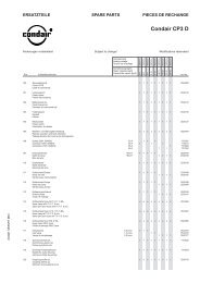
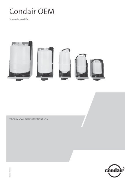
Condair OEMSteam humidifierTechnical Documentation1118599 EN 0908
Contents1 Introduction 41.1 To the very beginning 41.2 Notes on the technical documentation 42 For your safety 53 Product Overview 63.1 The various models 63.2 Delivery 73.3 Humidification system overview 83.4 Steam humidifier construction 93.5 Functional description 104 Basic planning 114.1 Selecting the unit 114.1.1 Model version 114.2 Options 134.2.1 Options overview 134.2.2 Option details 134.3 Accessories 154.3.1 Accessories overview 154.3.2 Accessory details 164.4 Additional planning instructions 175 Mounting and installation works 185.1 Safety instructions for mounting and installation works 185.2 Unit fitting 185.2.1 Humidifier location 185.2.2 Mounting the humidifier 205.2.3 Inspecting the installed unit 205.3 Steam installation 215.3.1 Positioning and mounting of the steam distribution pipes 215.3.3 Installing the steam hose 245.3.4 Installing the condensate hose 255.3.5 Inspecting the steam installation 265.4 Water installation 275.4.1 Performing the water installation 275.4.2 Inspecting the water installation 295.5 Electric installation 305.5.1 Electric installation overview 315.5.2 Inspecting the electrical installation 316 Operation 326.1 Operational safety instructions 326.2 Display and operating elements 326.3 Commissioning 336.4 Switching off 347 Maintenance 357.1 Instructions for Maintenance 357.2 Replacement/cleaning of steam cylinders 367.3 Removing and installing parts 377.4 Instructions for cleaning 427.5 Resetting maintenance indication (units with ECCM control only) 428 Fault elimination 438.1 Fault indication (units with ECCM control only) 438.2 Troubleshooting guide (units with ECCM control only) 448.3 Instructions for fault elimination 458.4 Replacement of fine-wire fuse on the control unit ECCM 458.5 Resetting fault indication (units with ECCM control only) 459 Technical data 46
2 For your safetyIntended useSteam humidifiers Condair OEM are intended exclusively for direct or indirect room humidificationwithin the specified operating conditions. Any other type of application, without the written consentof your Condair supplier, is considered as not conforming with the intended purpose. The manufacturer/suppliercannot be made liable for any damages resulting from improper use. The user bears fullresponsibility.Operation of the equipment in the intended manner requires that all the information in these instructionsis observed (in particular the safety instructions).Please contact your local Condair distributor if the steam humidifier Condair OEM is to be used in asteam-bath.General safety instructions– The steam humidifier Condair OEM must only be installed, operated serviced and in all cases repairedonly by persons who are adequately qualified to undertake such work and are well acquaintedwith the product. Ascertaining the qualifications is the customer‘s responsibility.– Caution, danger of electric shock! The Condair OEM is operated with mains voltage. Beforecommencing work on the Condair OEM, the unit is to be rendered inoperative in accordance withsection 6.4 and prevented from further inadvertent operation (isolate unit from the electrical powersupply, isolate water supply).– Observe all local safety regulations.– relating to the operation of mains-operated electrical and electronic equipment– and the provision of water, steam and electrical installations– Caution! For the electrical installation it is mandatory to comply with the regulations stated in the“DIN EN 60335-1” and “DIN EN 60335-2-98” standards (concerning the safety of electrical devices).In particular, it must be made sure that there is sufficient protection against inadvertent contactwith life parts.The Drain/Info key must be connected to enable manual draining of the steam cylinder and thedisplay of error codes (see Electrical Installation Instructions for ECCM - Component “S2”).– Poorly maintained humidification systems can endanger health. The servicing intervals shouldtherefore be adhered to without reservation and the servicing work carried out correctly.– If it is suspected that safe operation is no longer possible, then the Condair OEM should immediatelybe shut down and secured against accidental power-up. This can be the case under thefollowing circumstances:– if the Condair OEM is damaged– if the Condair OEM is no longer operating correctly– if connections and/or piping are not sealed or cables are loose– The Condair OEM must only be operated under the specified operating conditions (see section 9“Technical data”).– The Condair OEM is not IP protected. Make sure the units are installed in a drip-proof location andthe electrical connections are protected against inadvertent touching.– Caution! If the Condair OEM is installed in an area without a water drain, water sensors must befitted in the area, such that in the event of leakage in the water system, the water feed is safely shutoff.– Caution, danger of corrosion! In order to avoid damage, no corrosion-sensitive componentsshould be located in the area of the aerosol streams.– No work/repair should be carried out on the Condair OEM other than that described in these instructions.– Use exclusively original accessories and spare parts available from your Condair supplier.– No modifications must be undertaken on the Condair OEM, the accessories and the optionswithout the express written consent of the manufacturer.
3 Product Overview3.1 The various modelsSteam air humidifiers Condair OEM are available in a variety of models with different heating voltagesand steam capacities ranging from 1 kg/h up to 45 kg/h max..The following table provides an overview of the various models and their capacity ranges.Heating voltageVolt/SystemSteam capacitykg/hModelCondair OEMUnit sizesmall medium large1 -2 kg/h OEM 140 x230V/1N~/50..60 Hz3 - 4 kg/h OEM 240 x5 - 8 kg/h OEM 342 x2 - 4 kg/h OEM 263 x5 - 8 kg/h OEM 363 x400V/3~/50..60 Hz9 - 15 kg/h OEM 464 x16 - 25 kg/h OEM 674 x26 - 45 kg/h OEM 664 x2 - 4 kg/h OEM 243 x5 - 8 kg/h OEM 343 x230V/3~/50..60 Hz9 - 15 kg/h OEM 444 x16 - 21 kg/h OEM 654 x22 - 30 kg/h OEM 644 xThe steam humidifiers Condair OEM are designed for operation with raw water (tap water) or partiallysoftened water (softened water which has been diluted with tap water to approx. 1/3 of its original hardness).Important: If you want to operate the Condair OEM with partially softened water, pleasecontact your Condair distributor.The steam humidifiers Condair OEM are equipped, as standard, with an exchangeable steam cylinderand are configured for On/Off control via a humidistat. With the optional ECCM control unit thesteam humidifier can also be operated with continuous control. The equipment can be supplied withvarious other options.
3.2 DeliveryThe delivery includes:– Steam humidifier Condair OEM compl. (according to the model designation), equipped with thedesired options.Note: Desired options (cleanable steam cylinder, control unit, unit housing made of stainless steel,etc.) must be specified separately when ordering. Detailed information on this subject is found inchapter 4.2.– Water connection pipe with union nut G 3/4" and nipple 1/2"– Accessories according to chapter 4.3Note: Accessories for steam distribution (steam distribution pipes, steam hoses, etc.) must be specifiedseparately when ordering. Detailed information on this subject is found in chapter 4.3.
3.3 Humidification system overviewModels Condair OEM 1.., OEM 2... and OEM 3...6578911 Steam humidifier2 Electrical connection3 Water drainage Ø22 mm(accessory “DS22”)4 Filter valve (accessory “Z261”)5 Water supply (building side)6 Steam nozzle (accessory “W21”,for OEM 1.. and OEM 2.. only)7 Steam distribution pipe(accessory “41-..”)8 Steam hose (accessory “DS22”)9 Condensate hose (accessory “KS10”)423Models Condair OEM 4.., OEM 5... and OEM 6...67811 Steam humidifier2 Electrical connection3 Water drainage Ø30 mm(accessory “DS60”)4 Filter valve (accessory “Z261”)5 Water supply (building side)6 Steam distribution pipe(accessory “61-../81-..”)7 Steam hose (accessory “DS60/DS80”)8 Condensate hose (accessory “KS10”)2345
3.4 Steam humidifier constructionModels Condair OEM 1.., OEM 2... and OEM 3...1211109875634131415121 Housing (small)2 Control unit ECCM (option)3 Cable passage4 Drain connection5 Water supply connection6 Inlet valve7 Drain valve8 Steam cylinder9 heating electrodes10 Steam outlet11 Level sensor12 Water supply hose13 Water cup14 Filling hose15 Overflow hoseModels Condair OEM 4.., OEM 5... and OEM 6...121311109871415161231 Housing (medium, large)2 Control unit ECCM (option)3 Cable passage4 Water supply connection5 Inlet valve6 Drain connection7 Drain valve8 Steam cylinder9 heating electrodes10 Level sensor11 Steam outlet12 Water cup13 Water supply hose14 Overflow hose15 Filling hose16 Pressure compensation set546
3.5 Functional descriptionThe steam humidifier Condair OEM is a pressureless steam generator designed for direct or indirectroom humidification. The steam humidifier Condair OEM utilizes electrode heating. It is intended foruse with regular tap water or partially softened water.Steam generationAny time steam is requested, the electrodes (2) are supplied with voltagevia main contactor (1). Simultaneously, the inlet valve (7) opens and waterenters the steam cylinder (3) from the bottom via water cup (4) and supplyline (5). As soon as the electrodes come in contact with the water, currentbegins to flow between the electrodes, eventually heating and evaporatingthe water. The more the electrode surface is exposed to water, the higheris the current consumption and thus the steam capacity.Upon reaching the requested steam capacity, the inlet valve closes. If thesteam generation decreases below a certain percentage of the requiredcapacity, due to lowering of the water level (e.g. because of the evaporationprocess or drainage), the inlet valve opens until the required capacityis available again.If the required steam capacity is lower than the actual output, the inlet valveis closed until the desired capacity is achieved by lowering of the waterlevel (evaporation process).54321Level monitoring67A sensor provided in the steam cylinder cover detects when the water levelgets too high. The moment the sensor comes in contact with water, theinlet valve closes.Conventional On/Off control100 %0 %TimeContinuous controlX100100% %8080606040402020DrainageAs a result of the evaporation process, the conductivity of the water increasesdue to an escalating mineral concentration. Eventually, an inadmissibly highcurrent consumption would take place if this concentration process werepermitted to continue. To prevent this concentration from reaching a value,unsuitably high for the operation, a certain amount of water is periodicallydrained from the cylinder and replaced by fresh water.During the drainage process, the drain valve (6) is opened. Following apredetermined time of drainage, the drain valve is closed again.ControlUnits equipped with the optional ECCM control unit employ either On/Offcontrol (via an external On/Off humidistat) or continuous control (via anexternal or the built-in humidity controller) for steam production. Below aminimum controllable steam output, continuous control will work in two-pointoperation (on/off control).YX = steam capacity in %Y = output signal of controller10
4 Basic planningAll the data necessary for the selection and layout of a Condair OEM humidifier system are providedin the following chapters. The following planning steps are required:• Selecting the unit (see chapter 4.1)• Selecting options (see chapter 4.2)• Selecting accessories (see chapter 4.3)4.1 Selecting the unitThe selection of the unit is reflected in the type description:Model version (steam cylinder)Condair OEM 3634.1.1 Model versionModel version (steam cylinder)Steam humidifiers Condair OEM are available with different steam cylinders for different heating voltages.The maximum obtainable steam capacity is dependent on the type of steam cylinder used andthe heating voltage.Heating voltage 230V/1N~/50..60HzModel Condair OEM ... 140 240 342 ––– ––– –––Steam capacity kg/h 2 4 8 ––– ––– –––Heating voltage 400V/3~/50..60HzModel Condair OEM ... ––– 263 363 464 674 664Steam capacity kg/h ––– 4 8 15 25 45Condair OEM 363Heating voltage 230V/3~/50..60HzModel Condair OEM ... ––– 243 343 444 654 644Steam capacity kg/h ––– 4 8 15 21 30Note: If you require a unit with a different heating voltage, please contact your Condair supplier.Control voltageCondair OEM steam humidifiers are available with a control voltage of 220…240 VAC/50...60 Hz or24 VAC/50...60 Hz (Important: specify desired control voltage when ordering).11
Calculating the maximum required steam capacityThe maximum required steam capacity is calculated from the following formulas:V • ρm D= • (x2 - x1)1000orVm D= • (x2 - x1)1000 • εm D: maximum steam demand in kg/hV: volume of supply air portion per hour in m 3 /h (for indirect room humidification) or volumespace in case of simple air circulation per hour in m 3 /h (for direct room humidification)ρ: specific gravity of air in kg/m 3ε: specific volume of air in m 3 /kgx 2: desired absolute room air humidity in g/kgx 1: minimum absolute supply air humidity in g/kgThe values for ρ, ε, x2 and x1 can be gathered from the h,x-diagram or the Carrier-Diagram for moistair respectively.For a rough estimate of the calculated steam capacity, the following table can be used. The valueslisted in the table are based on a desired room air temperature of 20 °C and a desired relative roomair humidity of 45 %rh.Note: To roughly estimate the calculated maximum steam capacity for larger supply air portions or roomvolumes, the values listed in the table can be projected accordingly.Max. portion of supply air per hour in m 3 /h or volumespace in case of simple air circulation per hour in m 3 /hTemperature / rel. humidity of supply air-15 °C / 90%rh -5°C / 80%rh 5°C / 60%rhMax. steam capacityin kg/h500 650 800 41000 1250 1500 82000 2500 3000 154000 5000 6000 306000 7500 9000 45Important notes:– The required maximum steam capacity depends on the specific application and the installation.The calculated steam capacity based on the above formulas, the h,x diagram and the condition ofthe air to be humidified does not consider any steam loss (e.g. due to condensation in the steamhoses and the steam distributors), any heat loss of the unit as well as any absorption or release ofhumidity of materials located in the room being humidified.In addition, the calculated steam capacity does not consider any losses caused by the draining ratedepending on the water quality as well as any losses occur if the steam humidifier is operated on amains circuit with a ground fault circuit interrupter.The total amount of losses depends on the entire system and must be taken into consideration whencalculating the required steam capacity. If you have any questions regarding the calculation of thesteam capacity please contact your Condair supplier.– For systems where the max. required steam capacity varies extensively (e.g. for test facilities or forsystems with variable air volume flow, etc.), please contact your Condair supplier.12
4.2 Options4.2.1 Options overviewThe following table presents an overview of all options which are available for the steam humidifierCondair OEM.Model Condair OEM OEM 140 OEM 240OEM 243OEM 263OEM 342OEM 343OEM 363OEM 444OEM 464OEM 654OEM 674OEM 644OEM 664Cleanable steam cylinder(see details in chapter 4.2.2)Control unit(see details in chapter 4.2.2)Plug and cable set(see details in chapter 4.2.2)Pressure compensation setKit for mounting the filling cup at an extendedheight when operating the steamhumidifiers in systems with a duct airpressure of up to 1 kPa.––– ––– 1 x D3.. 1 x D4.. 1 x D6..ECCM ECCM ECCM ECCM ECCMA D D CP CPX 1) X 1)Unit housing of stainless steel x x x x x1)included in the standard delivery for these OEM units4.2.2 Option detailsSteam cylinderThe steam humidifier is available with two different types of steam cylinders:– Exchangeable steam cylinder type A... (standard version)– Cleanable steam cylinder type D... (option)The following tables present an overview of the steam cylinders used in the different models.Model Condair OEM OEM 140 OEM 240 OEM 243 OEM 263 OEM 342 OEM 343 OEM 363For water conductivity from 125 to 1250 µS/cmExchangeable steam cylinder A 140 A 240 A 243 A 263 A 342 A 343 A 363Cleanable steam cylinder ––– ––– ––– ––– D 342 D 343 D 363Model Condair OEM OEM 444 OEM 464 OEM 654 OEM 674 OEM 644 OEM 664For water conductivity from 125 to 1250 µS/cmExchangeable steam cylinder A 444 A 464 A 654 A 674 A 644 A 664Cleanable steam cylinder D 444 D 464 D 654 D 674 D 644 D 664If you have questions regarding the steam cylinders please contact your Condair representative.13
Control unit ECCMUnit for On/Off control via an external humidistat or for continuous control via an external or the builtinPI controller (proportional range Xp: 18 %, integral action time Tn: 540 s) with operating indicators(LEDs) for “Error”, “Warning/Maintenance” and “Steam production” and the option of connecting externalLEDs for remote indication of operational states.Admissible input signals:Control with external controller Control with internal PI controllerControl signalsHumidity sensor signals0 ... 10 VDC 0 ... 10 VDC (e.g. EGH110)2 ... 10 VDC 2 ... 10 VDC0 ... 20 mA 0 ... 20 mA4 ... 20 mA 4 ... 20 mAPotentiometer 1 ... 10 kΩ (e.g. HPH 1000)Humidistat (On/Off)The following illustration shows the control system applicable for the Condair OEM. The system issuited for direct room humidification and air conditioning systems with mainly recirculated air.The humidity sensor or humidistat respectively is preferably located in the exhaust air duct.A1 humidity sensorB1 ventilation interlockB2 airflow monitorB3 safety humidistatB4 humidistat (On/Off)ECCM Control unit for On/Off control viaan external humidistat or for continuouscontrol via an external orthe built-in PI controllerPIexternal continuous controller(e.g. PI-controller)ϕmaxK ΔpB1 B2CondairOEM B3ECCMECCMECCMPIB4ϕϕA1ϕϕB4Please contact your Condair supplier, if your application meets the following conditions:– Air conditioning systems with a high number of air exchanges– Systems with variable air volume flow– Test facilities with extreme control accuracy requirements– Rooms with a high variation in max. steam capacity– Systems with temperature fluctuations– Cold rooms and systems with dehumidification14
4.3 Accessories4.3.1 Accessories overviewThe following table presents an overview of all accessories which are available for the steam humidifierCondair OEM.Model Condair OEM 1.. 2.. 3.. 4.. 6..Steam nozzle(see details in chapter 4.3.2)Steam distribution pipe(see details in chapter 4.3.2)W21 W21 – – –number 1 1 1 – –41-.. 41-.. 41-.. 61-.. 81-..number 1 1 1 1 1Steam hose / meter DS22 DS22 DS22 DS60 DS80number 1 1 1 1 1Condensate hose / meterFilter valveHumidistatDuct air humidity sensorHumidity control potentiometer, duct1xKS10Z261 (1 pc. per system)all commercial models (1 pc. per system)EGH110 (1 pc. per system)HPH1000 (1 pc. per system)The following table provides an overview of the recommended heating contactors available as an option.Heating voltage 230 V/1N~/50...60 HzModel Condair OEM ... 140 240 342 – – –Steam capacity 2 4 8 – – –Heating contactor 230 V, 50...60 Hz K3-10 K3-10 K3-24 – – –Heating voltage 400 V/3~/50...60 Hznumber 1 1 1 – – –Model Condair OEM ... – 263 363 464 674 664Steam capacity – 4 8 15 25 45Heating contactor 230 V, 50...60 Hz – K3-10 K3-10 K3-10 K3-24 K3-32Heating voltage 230 V/3~/50...60 Hznumber – 1 1 1 1 1Model Condair OEM ... – 243 343 444 654 644Steam capacity – 4 8 15 21 30Heating contactor 230 V, 50...60 Hz – K3-10 K3-10 K3-24 K3-40 K3-40number – 1 1 1 1 1Note: Heating contactors operating at 24 V/50..60 Hz control voltage are available on request.15
4.3.2 Accessory detailsSteam distribution pipe 41-../61-../81-.. for indirect room humidificationThe steam distribution pipes 41-../61-../81-.. are selected on the basis of the duct width (for horizontalinstallation) or the duct height (for vertical installation) and the capacity of the steam humidifier.Important! Always select the longest possible steam distribution pipe (optimum humidification distance).LBSteam distribution pipe 1)for Condair OEMSteam distributionpipeDuct width (B)Type 41-.. Type 61-.. Type 81-.. Length in mm (L) 2) in mm41-200 200 210…40041-350 61-350 81-350 3) 350 400…60041-500 61-500 81-500 3) 500 550…75041-650 61-650 81-650 650 700…90041-800 61-800 81-800 800 900…110041-1000 61-1000 81-1000 1000 1100…130041-1200 61-1200 81-1200 1200 1300…160061-1500 81-1500 1500 1600…200061-1800 81-1800 1800 2000…240061-2000 81-2000 2000 2200…260081-2300 2300 2500…290081-2500 2500 2700…31001)Material: CrNi steel3)up to max. 30 kg/h steam capacity2)special length on requestSteam nozzle (for models OEM 1.. and OEM 2.. only)The steam nozzle “W21” can be mounted in the ventilation duct horizontally orvertically. Keep a minimum distance clearance (A) of 200 mm between nozzleopening and the opposite duct wall.16
4.4 Additional planning instructionsIn addition to the selection of the steam humidifier, the accessories and the options, other points shouldbe considered during planning. Please note the information in the following chapters:– Unit fitting (see chapter 5.2)– Steam installation (see chapter 5.3)– Water installation (see chapter 5.4)– Electric installation (see chapter 5.5)If you have other questions relating to planning that are not adequately covered by technical documentation,please contact your Condair representative. He will be happy to provide further assistance.17
5 Mounting and installation works5.1 Safety instructions for mounting and installation works– All mounting and installation work must be performed only by adequately qualifiedpersonnel. Ascertaining the qualifications is the customer‘s responsibility.– All local regulations relating to the execution of the respective installation work (Water,steam and electrical installation) must be noted and complied with.– All the information contained in this technical documentation relating to equipmentassembly and to water, steam and electrical installation must be unconditionallyobserved and complied with.– Caution - Danger from electric shock! The connection of the steam humidifier tothe mains electrical supply must not be made until all installation work has beencompleted.– Electronic components are very susceptible to electrostatic discharges. For the protectionof these components, measures must be taken during all installation work toprevent damage caused by electrostatic discharge (ESD–protection).5.2 Unit fitting5.2.1 Humidifier locationThe installation site of the steam humidifier depends largely on the location of the steam distributionpipe or the steam nozzle (see chapter 5.3.1), respectively. To ensure proper functioning of the steamhumidifier and to obtain an optimal efficiency, the following points must be considered and observedwhen choosing the location for the steam humidifier:– Install the steam humidifier so that the length of the steam hose is kept as short as possible(max. 4 m) and that the minimum bend radius (R= 300 mm) and up-slope (20 %) or down-slope(5 %) of the steam hose is observed (see chapter 5.3.3).– The steam humidifiers Condair OEM are designed for wall-mounting. Make sure that the construction(wall, pillar, floor-mounted console, etc.) to which the humidifiers are to be mounted, offers a sufficientlyhigh load-bearing capacity (take notice of the weight information found later in this chapter),and is suitable for the installation.Warning! Do not mount the steam humidifier directly to the ventilation duct (insufficient stability).– The Condair OEM is retaining heat during operation (max. surface temperature of the metal housingapprox. 60 - 80 °C). Make sure, therefore, that the construction (wall, pillar, etc.) to which the unitsare to be mounted, does not consist of heat-sensitive material.Warning! Make sure there is sufficient aeration at the site of location so that the admissibleambient temperature of 50 °C (40 °C for the control unit) is not exceeded.– Install the steam humidifier in such a manner that it is freely accessible with sufficient space availablefor maintenance purposes.18
Dimensions (in mm) and WeightsOEM 140 OEM 2.. OEM 3..20685192135Ø22.520686192135Ø22.5206 192113.596Ø22.5295.5333379.5417459.5497118.5147118.5147118.5 147Netweight:Grossweight:3 kg8 kgNetweight:Grossweight:3 kg8 kgNetweight:Grossweight:4 kg20 kgOEM 4.. OEM 6..330 329243 269122.5 134.5Ø30167164.5Ø45660705750793127.5185.5172215.5Netweight:Grossweight:6 kg26 kgNetweight:Grossweight:9 kg49 kg19
5.2.2 Mounting the humidifierUse a level to align the unit horizontally and vertically, then fix it to the support (wall, console, etc.)respecting the 4 points of fixation “A”.Caution! Correct fastening is the customer’s responsibility.abcAdOEM 1..OEM 2..OEM 3..CondairOEM 4.. OEM 6..ø 7mmabcd42.5 mm107.0 mm31.0 mm140.0 mm81.0 mm107.0 mm31.0 mm140.0 mm111.0 mm107.0 mm31.0 mm140.0 mm5.2.3 Inspecting the installed unitUse the following check list to ascertain that the installation was performed correctly:Is the unit in the correct place?(see chapter 5.2.1)Is the unit correctly aligned vertically and horizontally?Is steam humidifier properly secured?(stability of the carrying structure)Is there sufficient aeration so that the admissible ambient temperature of 50 °C (40 °C for the controlunit) is not exceeded?20
5.3 Steam installation5.3.1 Positioning and mounting of the steam distribution pipesThe location for the steam distribution pipes should be determined at the time of dimensioning the airconditioning system. Please note the following instructions to ensure proper humidification of the ductair.Calculating the humidification distanceThe water vapour, emitting from the steam distribution pipes, requires a certain distance to be absorbedby the ambient air so that it is no longer visible as steam. This distance is referred to as humidificationdistance “B N” and serves as a basis for the determination of the minimum distances from theupstream components in the system.Humidificationdistance B NExpansion and mixing zoneφ1: Supply air humidity before humidificationφ2: Supply air humidity after humidificationThe calculation of the humidification distance “B N” is dependent on several factors. For a rough estimationof the humidification distance “B N”, the following table is useful. Recommended standard valueslisted in this table are based on a supply-air temperature range of 15°C to 30 °C. The values givenapply to steam distribution pipes 41-../61-.. and 81-...Input humidityφ1 in %rhLength of humidification distance B Nin mOutput humidity φ2 in %rh40 50 60 70 80 905 0,9 1,1 1,4 1,8 2,3 3,510 0,8 1,0 1,3 1,7 2,2 3,420 0,7 0,9 1,2 1,5 2,1 3,230 0,5 0,8 1,0 1,4 1,9 2,940 – 0,5 0,8 1,2 1,7 2,750 – – 0,5 1,0 1,5 2,460 – – – 0,7 1,2 2,170 – – – – 0,8 1,7φ1 in %rh:φ2 in %rh:Relative supply air humidity prior to humidification at the lowest supply air temperatureRelative supply air humidity after the steam distribution pipe at maximum capacityExamplegiven:humidification distance B N:φ1= 30 %rh, φ2= 70 %rh1,4 m21
Minimum distances to be observedTo prevent the water vapour, that is emitting from the steam distribution pipe, from condensing ondownstream system components, a minimum distance to the steam distribution pipe must be observed(depends on the humidification distance “B N”).before/after constriction after expansion before bend0.5 x B N 0.5 x B N B Nbefore branch before diffuser before control sensorB N B N 5 x B Nbefore/after filter/registerbefore/after fan, zone exit1.5 x B N * 5 cm B N B N2,5 x B Nbefore aerosol filterInstallation notes and dimensionsThe steam distribution pipes are designed for either horizontal installation (on the duct wall) or, withaccessories, for vertical installation (in the duct floor). The outlet orifices should always point upwardsand at right angles to the airflow.If possible, the steam distribution pipes should be installed on the pressure side of the duct (max.duct pressure 1000 Pa, Condair OEM 4.. and OEM 6.. with pressure compensation set only). If thesteam distribution pipes are installed on the suction side of the duct, the maximum vacuum must notexceed 500 Pa.Select a location for the installation, tailored to suit your duct (see the following illustrations) and positionthe steam distribution pipes in the duct so that a uniform distribution of steam is achieved.22
In positioning the steam distribution pipes, the following dimensions should be observed.1/21/21/2 1/2H2/31/3min. 85 mmHHmin H= 250 mmH 400 mmmin H= 200 mmGuidelines for dimensioning the ventilation ducts– To facilitate the installation of the steam distribution pipes and for control purposes, a sufficientlysized control opening should be planned.– Within the range of the humidification distance, the ventilation duct should be waterproofed.– Air ducts passing through cold rooms should be insulated to prevent the humidified air from condensingalong the duct wall.– Poor airflow conditions within the air duct (e.g. caused by obstacles, tight bends, etc.) can lead tocondensation of the humidified air.– Steam distribution pipes must not be mounted to round ducts.If you have questions relating to the dimensioning of ventilation ducts in combination with steam humidifiersCondair OEM, contact your Condair supplier.Installing the steam distribution pipes/steam nozzleDetailed information on the installation of steam distribution pipes and the steam nozzle can be foundin the separate “Mounting Instructions” for this products.23
5.3.3 Installing the steam hoseImportant! Use original Condair steam hose exclusively. Other types of steam hoses can cause undesiredoperational malfunctions.Instructions for the hose layoutInitially, the steam hose must always be led with an upslope of at least 20 % over a minimum heightof 300 mm above the top edge of the humidifier and then lead the hose with a minimum upslope of20% and/or a minimum downslope of 5% to the steam distribution pipe.min. 5 %min. 20 %min. 300 mmRmin.300 mmmax. 4 mmin. 20 %max. 4 mRmin.300 mmmin. 300 mmmin. 5 %min. 20 %min. 5 %min. 20 %Rmin.300 mmmax. 4 mmin. 300 mmmin. 20 %max. 4 mRmin.300 mmmin. 300 mm– Steam hoses must be prevented from sagging (condensate pockets); if necessary, support with pipeclamps, trough or wall brackets, or install a condensate drain in the steam hose.If sagging of the steam hose can not be prevented, a condensate drain at the lowest point of thesteam hose must be installed (see illustration above).– The steam hose should be kept as short as possible (max. 4 m) while observing the minimumbend radius of 300 mm. Important! Allowance must be made for a pressure loss of 10 mm watercolumn (approx. 100 Pa) per meter steam hose.– Reductions in the cross section such as kinks should be avoided throughout the entire length of thehose. The installation of a stop cock in the steam hose is not permissible.– Important! When deciding on the length and layout of the hose, it should be noted that the steamhose may become somewhat shorter with progressive ageing.24
Securing the hoseThe steam hose must be secured to the steam distribution pipe and steam cylinder by means of hoseclamps.Caution! Do not overtighten the hose clamp on the steam connector of the steam cylinder.Steam line with fixed pipingFor steam lines with fixed piping, the same instructions apply to the laying of the piping as alreadydescribed. The following additional notes should be observed:– The minimum internal diameter of 22 mm, 30 mm or 45 mm respectively should be applied overthe whole length of the piping.– Use exclusively Cu pipe (operation with untreated water) or stainless steel (min. DIN 1.4301).– To minimize the condensate formation (=loss), the steam pipes must be insulated.– The minimum bend radius for solid pipes is 4-5 x internal diameter.– Connection of the steam pipes to the steam distribution pipe and steam humidifier is effected bymeans of short lengths of steam hose secured with hose clamps. Connection to the steam humidifieris secured via a G 2” coupling.– Important! Allowance must be made for a pressure loss of 10 mm water column (approx. 100 Pa)per meter length or per 90° bend.5.3.4 Installing the condensate hoseImportant! Use original Condair condensate hose exclusively. Other types of hoses can cause operationalmalfunctions.Instructions for the hose layoutCondensate hose is led down with a minimum slope of 20 %, in the form of a siphon (min. hosebend radius Ø200 mm), directly into a discharge funnel.min. 300 mmmin. 20 %min. 300 mmmin. 20 %Ømin. 200 mmØmin. 200 mmmin. 20 %min. 300 mmmin. 300 mmmin. 20 %Ømin.200 mmØmin.200 mmImportant! Before putting the unit into operation, the siphon of the condensate hose must be filledwith water.25
5.3.5 Inspecting the steam installationUse the following check list to ascertain that the steam installation was performed correctly:– Steam distribution pipeSteam distribution pipe correctly positioned and secured (screws tightened)?Are the outlet orifices at right angles to the air flow direction?– Steam hoseMaximum length of 4 m?Minimum bend radius of 300 mm (4-5 x internal diameter with fixed piping)?Have the instructions for hose positioning been followed?Steam hose: no sagging (condensate pocket)?Rigid steam lines: properly insulated? Correct installation material used? Minimum internal diametermaintained?Steam hose securely attached with clamps?Heat expansion during operation and shortening of the hose with ageing taken into consideration?– Condensate hoseDownslope of at least 20 %?Siphon existing and filled with water?Condensate hose correctly fixed?26
5.4 Water installationAll work concerning the water installation must be performed only by adequately qualifiedpersonnel (e.g. plumbers). Ascertaining the qualifications is the customer‘s responsibility.Please observe all local regulations concerning the installation of appliances to the mainsand waste water systems.Warning - danger of electric shock! For all installation work, the steam humidifier mustbe disconnected from the mains supply (inasmuch as installed) and secured againstunintentional re-connection.5.4.1 Performing the water installationOverview water installationOEM 4..OEM 6..G 3/4"G 1/2"G 3/4"G 1/2"OEM 1..OEM 2..OEM 3.. 1ø30 mm13ø22 mm3A50 cm50 cm4A42 7 6 52 7 6 58 9 108 9 101 Water connection pipe with union nut G 3/4" (on unit side) andnipple G 1/2" (on installation side)2 Water supply pipe (min. inner Ø: 8 mm)3 Water drain connection Ø22 mm (OEM 1.. to OEM 3..) or Ø30 mm (OEM 4.. and OEM 6..)4 Drain pipe min. inner Ø 22 mm (OEM 1.. to OEM 3..) or min. inner Ø 30 mm (OEM 4.. andOEM 6..), min. 50 cm directed vertically downwards5 Pressure reducing valve (compulsory for water pressures >10 bar, building side)6 Manometer (installation recommended, building side)7 Filter valve (accessory “Z261”)8 Funnel (building side)9 Siphon (min. inner Ø: 30 mm, building side)10 Drain line, building side (min. inner Ø: >30 mm)27
Water supplyThe water feed pipe is to be connected via the filter valve (accessory “Z261”), to the connection on theunit (see detailed illustration). The installation of the filter valve should be made as close as possibleto the steam humidifier.Note: Instead of the filter valve, a shut-off valve (essential) and a water filter 5 µm (not essential, butadvantageous) can be used.Warning - danger of damage! Union nut at the humidifier connection must be hand-tightenedonly.The following connection specifications must be observed:– Connection: union nut G 3/4" (on unit side) and nipple G 1/2" (on installation side)– Min. inner Ø of supply line: 8 mm– Admissible mains pressure 1.0 to 10.0 bar (hammer-free system)For mains pressures >10 bar, connection must be made via pressure reducing valve (adjusted to2.0 bar). For mains pressures
5.4.2 Inspecting the water installationUse the following check list to ascertain that the installation has been performed correctly:– Water supplyHas filter valve (accessory “Z261”) or shut-off valve and filter 5 µm respectively been installed insupply line?Have admissible water pressure (1.0 – 10 bar) and temperature (1 – 40 °C) been observed?Does supply capacity match the humidifier(s)?Are all pipes properly secured (threaded connections tightened)?Is the feed pipe properly sealed?– Water drainHas minimum inside diameter of drain pipes been maintained at least 22 mm (models OEM 1..to OEM 3..) or 30 mm (models OEM 4.. and OEM 6..) throughout the entire length?Has drain pipe been installed with a downslope of at least 10 %?Has the heat resistance of the material used been verified to be at least 100°C?Are hoses and lines properly secured (hose clamps and threaded connections tightened)?29
5.5 Electric installationA separate electrical installation manual is available for the control unit ECCM, giving all necessarydetails (connection data, diagrams, etc.) for the correct installation of the electrics. The directions in theelectrical installation instructions must be followed. Please also note the following instructions:– All work concerning the electric installation must be performed only by adequately qualified person-nel (electrician or workman with equivalent training). Ascertaining the qualificationsis the customer‘s responsibility.– Caution electrical hazard! The unit incorporating the Condair OEM (e.g. air conditioningcabinet) must be protected in a way that no live components and wires can betouched when the Condair OEM is in operation.– Warning - danger of electric shock! The steam humidifier may be connected toelectric mains only after all installation work has been completed.– Please observe all local regulations concerning the electric installation.– Warning! The electronic components of the control unit are very susceptible to electrostaticdischarges. For the protection of these components, measures must be takenduring all installation work to prevent damage caused by electrostatic discharge(ESD–protection).– Caution! For the electrical installation all regulations according to “DIN EN 60335-1”and “DIN EN 60335-2-98” standards regarding the safety of electrical devices must bestrictly adhered to. In particular, it must be made sure that there is sufficient protectionagainst inadvertent contact with life parts.– For trouble-free operation we recommend using the optional heating contactors (seetable in chapter 4.3.1).30
5.5.1 Electric installation overviewUcUp21F2F1K ΔpB1 B2CondairOEM B3Q2Q16ECCMECCMECCMϕmax5B4ϕϕA1ϕϕB4431 Supply heating voltage Up2 Supply control voltage Uc3 External continuous controller4 Control unit ECCM(On/Off control or continuous control)5 External safety circuit6 Steam humidifierA1 Humidity sensor (room/exhaust)B1 Ventilation interlockB2 Airflow monitorB3 Safety humidistatB4 HumidistatQ1/Q2 External service switch or plug-typeconnectorsF1/F2 External power supply fuses5.5.2 Inspecting the electrical installationInspect for correct installation in accordance with the following checklist:Do the details on the rating plates for heating and control voltage match the relevant network voltage?Are the voltage supplies (heating and control voltage) correctly fused?Is the service switch “Q” installed in the supply line for to the heating and control voltage?Are all components correctly connected according to the connection diagram?Are all regulations according to “DIN EN 60335-1” and “DIN EN 60335-2-98” standards regardingthe safety of electrical devices (in particular, protection against inadvertent contact with life parts)complied with?Is the Drain/Info key connected to the ECCM control unit correctly (see “Electrical Installation CondairECCM”)?Are all connecting cables fastened?Are the units configured correctly (see “Electric-Installation Condair ECCM”)?31
6 Operation6.1 Operational safety instructions– Initial commissioning: Before the steam humidifier is put into operation for the first time,all installations and the unit configuration must be inspected by the responsiblepersons to see that everything is correct (see also checklist for the individual installations).Any defects must be expertly dealt with before commissioning.– The Condair OEM steam humidifier may only be started and operated by persons whoare familiar with the unit and who have adequate qualifications for this work. Checkingthis qualification is the customer’s concern.– Warning - danger of electric shock! Before actuating the service switches of thepower supply lines (heating and control voltage) to the Condair OEM make sure theunit incorporating the Condair OEM (e.g. air conditioning cabinet) is duly closed andno live parts can be touched.6.2 Display and operating elementsThe figure below shows the display and operating elements of the ECCM control unit (available asan option). The ECCM control unit allows the connection of a drain key and an On/Off switch. Pleaseconsult the instructions supplied with the control unit.ECCM control unit1 On/Off switch2 Drain/info key5433 Error display (red LED)4 Warning and information display (yellow LED)5 Steam production display (green LED)1232
6.3 CommissioningIn order to start up the steam humidifier, take the following steps:• Check steam humidifier and installations for damage.Warning! Damaged units or units with damaged installations must not be put into operation.• Open the shut-off valve to the water feed.• Switch on the service switch for network supplies (heating and control voltage).• Switch on the steam humidifier via the On/Off-switch.The following applies only to units equipped with ECCM control: After switching on the controlunit ECCM carries out a system test, during which all the LEDs on the control unit light up in sequence.After the system test the unit is ready for operation.If, after the system test:– the yellow LED blinks permanently, the drain/info key has been pressed.– the yellow LED lights permanently, steam cylinder maintenance is due (see chapter 7) or themaintenance indication has not been reset (see chapter 7.5).– the yellow LED and the red LED light permanently, the steam cylinder maintenance (seechapter 7) has not been executed or the maintenance indication has not been reset (see chapter7.5).– the red LED light permanently, a fatal malfunction has occurred (see chapter 8).In this case press the drain/info key (at least 3 seconds) until operating status display is activated(see below) and consult the information given in chapter 8 “Fault elimination”.After switching on the unit is ready for operation. As soon as the humidity controller or the humidistatrequires humidity, power is switched on for heating. The inlet valve opens (slight delay) and the steamcylinder fills with water. As soon as the submerged electrodes heat the water up the green LED lights up(only on units equipped with ECCM control) and after a few minutes (approx. 5–10 minutes, dependingon the conductivity of the water) steam is produced.Note: If the water has low conductivity, it is possible in the first few hours of operation that the maximumsteam output is not achieved. This is normal. As soon as the water reaches adequate conductivitythrough the vaporization process, the steam humidifier will work at maximum output.Operating status display (only on units equipped with ECCM control)By pressing the drain/info key for at least 3 seconds, the steam humidifier’s current operating statuscan be displayed by the LEDs on the control unit.Note: The status indication is automatically reset after 5 minutes, or manually by pressing the drain/infokey again.– The green LED current steam output in % of maximum output by blinking at regular intervals:Green LED blinking... 1x 2x 3x 4x 5x 6x 7x 8x 9x 10xSteam output in % 10 20 30 40 50 60 70 80 90 100– The yellow LED blinking at regular intervals shows that there is a malfunction which the controlunit ECCM is trying to remedy. The blinking frequency of the LED indicates the type of problem.In-depth details are found in chapter 8.– The red LED blinking at regular intervals shows that there is a malfunction which the control unitECCM cannot remedy. The blinking frequency of the LED indicates the type of problem. In-depthdetails are found in chapter 8.33
Remote operation and fault indication via external LEDs (with ECCM control only)Assuming external LEDs are connected to the respective terminals of the ECCM control unit the followingstates of operation can be displayed remotely:Operation statusOutput activatedon ECCM control unitDisplay on ECCM control unit“Error”, Humidification off H1 “Error” red LED lights upSteam cylinder maintenance due H2 “Maintenance” yellow LED lights upSteam production H3 “Steam production” green LED lights up6.4 Switching offIn order to switch off the steam humidifier, e.g. for maintenance work, take the following steps:• Close shut-off valve to the water feed.• Press drain/info key briefly. The heating voltage is cut off and the steam cylinder empties. Theyellow LED blinks (only on units equipped with ECCM control).• Wait until the steam cylinder is empty (approx. 5-10 minutes). Then switch off the unit via theOn/Off switch and secure switch in “off” position against accidentally being switched on.• Disconnect steam humidifier from electricity supply: Switch off all service switches to networksupplies (heating and control voltage) and secure switch in “off” position against accidentallybeing switched on.34
7 Maintenance– All maintenance work should only be carried out by trained and qualified personnel,who are familiar with the related dangers. Checking the qualification is the customer’sconcern.– The instructions and details for maintenance work must be followed and upheld.– Only the maintenance work described in this documentation may be carried out.– Only use original Condair spare parts to replace the steam cylinder or faulty parts.– Before starting maintenance work the Condair OEM must be switched off asdescribed in chapter 6.4 and secured against accidental switching on.7.1 Instructions for MaintenanceTo maintain operational safety the Condair OEM steam humidifier must be maintained at regular intervals.This is differentiated between the first maintenance after approx. 500 operating hours “I”,steam cylinder maintenance after the yellow LED lights up “II“ (only on units equipped with ECCMcontrol) and annual maintenance “III”.Below you will find a summary of the work to be carried out for each of the three maintenance stages.Components Interval Work to be doneI II IIICleanable steam cylinderType D..X X X Clean steam cylinder and electrodes and check for damage,replace if necessary. Note: The steam cylinder mustbe replaced after a maximum operating time of 5,000 hrs.(see also chapter 7.2).Electrode plug X X X Check to see firmly positioned (remove cover and tightenfixing screw with hexagonal head socket wrench).Warning! This work should only be carried out by an electrician.Replacement steam cylinderType A..XRemove and replace.Drain valve X Remove, disassemble and clean, replace if necessary.Drain duct from unit X Inspect, clean if necessary.Drain pipe inclus. siphon X Inspect, clean if necessary (decalcify and rinse out).Steam installation X X Inspect steam and condensate hoses for cracks and to seethat they are correctly attached, replace faulty hoses.Water installation X X Inspect water hoses in the unit for cracks and to see thatthey are correctly attached, replace faulty hosesCheck supply pipe is tight, make tight if necessary. Cleanwater filter, if available.Electrical installation X X Check all cables in the unit are firmly positioned and examinestatus of insulation.35
7.2 Replacement/cleaning of steam cylindersLife timeThe life time of the steam cylinders and electrodes depends on various factors (water quality, conductivity,average steam output).The following apply in general: When the yellow LED (only on units equipped with ECCM control)lights up:– Replacement steam cylinder Type A... should be replaced.– Cleanable steam cylinder Type D... should be cleaned, or replaced if the maximum life time(5,000 hrs) has already been reached.Note: Only the cleanable steam cylinder Type D... can be cleaned. The replacement steam cylinderType A... must always be replaced on expiry of the tool life.The following diagram gives you guide values for the tool life of the replacement steam cylinder andthe cleaning intervals for the cleanable steam cylinder.GH3020Service intervals for steam cylinderdepending on steam production in hoursd10DTf504030THCaCO3mg/l (ppm)50040010Life timerange203002005500 1000 2000 4000100Time in hoursGH: GesamthärteDT: Dureté totaleTH: Total hardness36
7.3 Removing and installing partsWarning! Before starting to remove parts, the steam humidifier must be switched off asdescribed in chapter 6.4 and secured against accidental switching on.Warning - danger of burning! If steam was produced until shortly before switching off,the steam cylinder will be hot. Therefore you should wear well-insulated gloves or waituntil the steam cylinder is cool to remove parts.Removal and installation of the steam cylinders1 321. Release hose clamp on the steam hose using screwdriver and detach hose upwards from the steamconnection.2. Detach plug on electrode cable and on the sensor cable.3. Carefully push steam cylinder upwards from the holding devices on the side or the rear respectivelyand take out from front.Warning! Put steam cylinder down carefully.37
Installation of the steam cylinder follows the reverse sequence. Please note the following instructions:– Before installation of the steam cylinder in the unit check the O-ring in the drain valve for damageand replace if necessary.– Place steam cylinder in the holding devices on both sides of the unit or the rear respectively. Carefullypush steam cylinder downwards into the drain valve until it stops.– Mount the plugs of the electrode and sensor cables according to the following table to the respectiveelectrode or sensor connections.Steam cylinder typeA140 A/D343 A/D654A240 A/D363 A/D644A/D342 A/D444 A/D664A/D464A/D674CableconfigurationbrownSensorwhiteblackredblackbrownSensorwhitebrownredblackblackredbrownSensor white– Fasten steam hose on steam connector of the cylinder with hose clamps. A leaky steam hose cancause damp damage in the interior of the unit.Caution–Danger of damage! Do not overtighten the hose clamp on the steam connector of thesteam humidifier.38
Disassembly and assembly of the cleanable steam cylinder type D...1 3 421. Fasten electrode snap fastenings and push electrodes approx. 2 cm downwards into the steamcylinder.2. Release clamp clips of the cylinder cover and raise cover.3. Remove carefully electrodes by lifting upwards.4. Remove O-rings from the electrodes.Note: Intact O-rings can be reused.The assembly of the cleanable steam cylinder follows the reverse sequence. Please note the followinginstructions:– Before assembling of the steam cylinder check all O-rings for damage and replace if necessary.– Place O-rings on the electrodes. Insert electrodes in steam cylinder cover. Snap fastening mustengage.– Mount cylinder cover in the correct position (align the two cams on the steam cylinder body withthe corresponding grooves in the cylinder cover, do not forget the O-ring) and fast cover with clampclips.39
Removal and installation of drain valvesThe steam cylinder has to be removed first, as already described, before removing the drain valve.41321. Detach electric cable.2. Release hose clamp and detach filling hose.3. Release two fixing screws using Philips screwdriver and remove drain valve.4. Disassemble drain valve.Installation of the drain valve follows the reverse sequence.40
Removal and installation of the inlet valveThe steam cylinder must not be removed, before removing the inlet valve.221144331. Detach electric cable.2. Release hose clamp and detach hose.3. Release union nut of water supply pipe and remove.4. Release two fixing screws using Philips screwdriver and remove inlet valve.Installation of the inlet valve follows the reverse sequence.41
7.4 Instructions for cleaningCleaning the steam cylinder Type D...Details on cleaning the cleanable steam cylinders Type D... can be found in the separate documentationto this unit component.• Knock off any limescale as much as possible.Note: If the parts are heavily calcified, place them in an 8% formic acid solution, until the limescaledisintegrates.• Then wash parts with a hand-wash temperature soap solution and rinse well.Cleaning the interior of the unitWipe components in the interior of the unit with a damp cloth without cleaning agent. Heavily calcifiedparts, e.g. the drain duct, the drain valve and the inlet valve may be cleaned with normal cleaningand decalcifying agents.Warning! Take care that the electrical connections and the electronic components remain dry.Notes on the cleaning agentThe instructions for use of the cleaning agent must be observed and followed. In particular: detailson personal safety, environmental safety and all restrictions on use.The use of disinfectants is only permitted if they do not leave any toxic residues. The parts mustbe thoroughly rinsed with water after cleaning.Warning! Do not use any solvents, aromatized or halogenized hydrocarbons or other aggressivesubstances.Always maintain local environmental regulations.7.5 Resetting maintenance indication (units with ECCM control only)After completing maintenance work, the maintenance indication can be reset as follows:• Press drain key with the unit switched off and hold down.• Switch on steam humidifier using On/Off switch.• Hold drain key down until the system test is completed (approx. 10 seconds).42
8 Fault eliminationImportant! Most operational malfunctions are not caused by faulty equipment but rather by improperinstallation or disregarding of planning guidelines. Therefore, a complete fault diagnosis always involvesa thorough examination of the entire system. Often, the steam hose connection has not been properlyexecuted, or the fault lies with the humidity control system.8.1 Fault indication (units with ECCM control only)LED on control unit ECCMDescriptionyellowredblinks permanently ––– Drain/info key has been pressed shortlylights ––– Steam cylinder maintenance due or maintenance indication notreset.lights lights Steam cylinder maintenance not executed or maintenance indicationnot reset.––– lights Fatal malfunction.If the yellow or red LED lights/blinks, press drain/info key (at least 3 seconds) until yellow (“Warning”)or red (“Error”) LED starts blinking intermittently. The amount of “blinks” per interval indicatesthe type of malfunction.– Yellow LED “Warning” blinks intermittentlyA malfunction is present. The control unit checks whether there is a temporary problem (e.g. watersupply interrupted for a short time) or whether it can resolve the problem by taking necessary measures.Such malfunctions set the unit into the “fault elimination status”.– Red LED “Error” blinks intermittentlyThe control unit, after several attempts, fails to solve the problem (number of attempts depends onthe type of malfunction) or the problem obstructs further operation. In this case the heating voltageis interrupted via the main contactor.43
8.2 Troubleshooting guide (units with ECCM control only)“Warning”yellow LEDblinks1xSafety circuitopen2xMax. filling levelof steam cylinderreached3xPermissible fillingtime exceededfor more than20 minutes(first automaticcleaning cycle)“Error”red LED blinksCause--- Ventilator interlock open.Air flow monitor activated.Safety humidistat activated.--- Water conductivity too low (after initialoperation).Water conductivity too low for type ofsteam cylinder.Phase failure heating voltage.3xPermissible fillingtime exceeded formore than4 hours.Note: if the Jumper “L” is removedfrom the ECCM control unit (ex factory:jumper is installed), the unit automaticallytriggers an error without prior warningif the admissible filling time has beenexceeded for more than 20 minutes.4xSteam cylinderneeds servicing4xInterval for steamcylinder serviceexceeded formore than 72hoursNote: if the Jumper “K” is installedon the ECCM control unit (ex factory:no jumper is installed), the unit remainsin warning status even if the intervaltime has been exceeded for more than72 hours. No error is triggered.6xElectrode currentto high7xFoam detection inthe steam cylinder6xElectrode currentto high7xFoam controlimpossible--- 8xMain contactorjammed9xDrain valveblocked9xDrain valveblocked--- 10xRotary switch inwrong positionCurrent/peak-current cut-off.Water supply obstructed, water pressuretoo low, inlet valve defective.Excessive steam back pressure,through it water loss via filling cup.Drain valve is leaking.Interval for steam cylinder serviceexceeded.Mineral deposits and/or electrodesspent.Steam cylinder (electrodes) defective.Faulty auto-drain function.Faulty drain valve/coil.Steam cylinder outlet obstructed.Water conductivity too high for type ofsteam cylinder.Formation of foam in steam cylinder.Main contactor jammed in activatedposition.Drain valve blocked or defective.Steam cylinder outlet blocked.Rotary switch on control unit ECCM isset to an invalid position.RemedyIf applicable, check/turn on ventilationsystem.Check ventilator/filter.Wait, if applicable, check system orincrease safety humidistat.Wait.Select correct steam cylinder type.Check mains fuse(s) and replace ifapplicable.See “Electric installation CondairECCM”.Open shut-off valve in the water supplypipe, clean water inlet filter, checkwater pressure, inspect/replace inletvalve.Inspect steam installation, install pressurecompensation kit (see options).Clean/replace drain valve.Replace steam cylinder type A, cleansteam cylinder type D (see chapter 7).Important! Refer to chapter 7.5 forresetting the maintenance indicator.Replace steam cylinder or electrodesInspect installation/control system.Replace drain valve/coil.Clean/replace steam cylinder.Select correct steam cylinder type.Empty/flush steam cylinder.Set jumper on “DRN” (see “Electricinstallation Condair ECCM”).Check/replace main contactor.Clean/replace drain valve.Clean steam cylinder outlet.Set rotary switch to the position forthe corresponding steam cylindertype (see “Electric installation CondairECCM”).44
8.3 Instructions for fault eliminationWhen eliminating faults, the steam humidifier must be taken out of operation (seechapter 6.4).Warning danger of death! Take care that the electricity supply to the main contactoris cut off (test with voltage tester).Repair work and replacement of faulty components may only be carried out byyour Condair representative’s service technician or personnel authorized todo the work!Warning! Malfunctions relating to the electrical installation must only be repairedby authorized personnel.Electrical components are very sensitive to electrostatic discharge. Measures mustbe taken to protect these components against electrostatic discharge during all repairwork (ESD protection).Only use original spare parts from your Condair supplier for the replacement of faultycomponents.8.4 Replacement of fine-wire fuse on the control unit ECCMWarning: Danger of death! Before changing the fuse on the control unit ECCM, the CondairOEM must be switched off and secured against unintentional reconnection as describedin chapter 6.4. Take care that the electricity supply to the control unit ECCM is disconnected(check with voltage tester).Important! If the fine-wire fuse on the control unit ECCM blows this is usually due to a faulty coil of theinlet or drain valve or the main contactor. Therefore you should test these components before replacingthe fuse.Only use a fuse of the given type with the specified nominal current strength to replace the fuse on thecontrol unit ECCMWarning! It is not permitted to use repaired fuses or to short-circuit the fuse holder.(250 mA, slow acting for 230 VAC version)or(2 A, slow acting for 24 VAC version)8.5 Resetting fault indication (units with ECCM control only)In order to return the steam humidifier to operation after fault elimination (“Error“, red LED lit), the steamhumidifier must be switched off for approx. 5 seconds and then switched on again.Note: Resetting maintenance indication see chapter 7.5.45
9 Technical dataHeating voltage 230V/1N~/50..60HzModel Condair OEM...Steam capacity kg/hMax. power consumption in kWOEM 14021.5OEM 24043OEM 34286Heating voltage 230V/1N~/50..60HzModel Condair OEM...Steam capacity kg/hMax. power consumption in kWOEM 26343OEM 36386OEM 4641511.3OEM 6742518.8OEM 6644533.8Heating voltage 230V/1N~/50..60HzModel Condair OEM...Steam capacity kg/hMax. power consumption in kWOEM 24343OEM 34386OEM 4441511.3OEM 6542115.8OEM 6443022.5Control voltageOperating conditionsAdmissible water pressureWater qualityAdmissible water temperatureAdmissible ambient temperatureAdmissible ambient humidityAdmissible duct air pressureType of protectionConformityEquipment/DimensionsSteam cylinder typeHousing (WxHxD) in mmNet weight in kgOperating weight in kgA1..A2..A3../D3..A4../D4..A6../D6..x192x333x20638230 VAC/50...60 Hz or 24 VAC/50...60 Hz1...10 barDrinking water with a conductivity of 125 - 1250µS/cm1...40 °C1...50 °C (Control unit 1...40 °C)max. 75 %rh, non-condensing-0.5kPa..1.0kPa (Condair OEM 4.. and OEM 6..with pressure compensation set only)IP00produced according VDE regulations 0700 and 0700 part 98x192x417x20638x192x497x206320x269x705x243426x329x793x330949x329x793x330949OptionsControl unit ECCM(on/off control andcontinous control)Plug and cable setADCPxxxxxxxxxxxxAccessoriesSteam nozzleSteam distribution pipeSteam hose / meterCondensate hose / meterW2141-..61-..81-..DS22DS60DS80KS10xxxxxxxxxxxxxxxxxxxx46
© Walter Meier (Climate International) Ltd. 2003, Printed in SwitzerlandTechnical modifications reserved47
Consulting, Sales and Service:Solutions for Indoor ClimateReg.No. 40002-2Manufacturer:Walter Meier (Climate International) Ltd.Talstr. 35-37, P.O. Box, CH-8808 Pfäffikon (Switzerland)Phone +41 55 416 61 11, Fax +41 55 416 62 62www.waltermeier.com, international.climate@waltermeier.com