- Page 1 and 2:
NUREG/CR-6983 BNL-NUREG-81548-2008
- Page 3 and 4:
Seismic Analysis of Large-Scale Pip
- Page 5 and 6:
FOREWORD This report documents the
- Page 7 and 8:
Figure 2-7 Model B Simplified Pipin
- Page 9 and 10:
Figure 4-64 Acceleration A2 Compari
- Page 11 and 12:
In the final phase of the test prog
- Page 13 and 14:
Continued investigation of the subj
- Page 15 and 16:
1 INTRODUCTION Prior to the establi
- Page 17 and 18:
2 DESCRIPTION OF JNES/NUPEC TEST PR
- Page 19 and 20:
Photographs of the DM Test Piping a
- Page 21 and 22:
Design Method Confirmation Test Ult
- Page 23 and 24:
Stress (N/mm 2 ) Figure 2-1 Monoton
- Page 25 and 26:
Hoop Strain (%) 18 16 14 12 10 8 6
- Page 27 and 28:
φ76.3 7.8 1500 Variable Hanger Sma
- Page 29 and 30:
Figure 2-9 Overview of Design Metho
- Page 31 and 32:
Figure 2-11 DM Test Nozzle 17
- Page 33 and 34:
Figure 2-13 DM Test Spring Hanger 1
- Page 35 and 36:
Figure 2-15 DM Test Accelerometer L
- Page 37 and 38:
Figure 2-17 DM Test Strain Gage Loc
- Page 39 and 40:
Figure 2-19 US Test Piping System S
- Page 41 and 42:
Figure 2-21 US Test Elbow 2 and Add
- Page 43 and 44:
Figure 2-23 US Test Accelerometer L
- Page 45 and 46:
Figure 2-25 US Test Strain Gage Loc
- Page 47 and 48:
Displacem ent(m m ) S train(%) 100
- Page 49 and 50:
Figure 2-30 US Test Elbow 2 Fatigue
- Page 51 and 52:
3 BNL LINEAR ANALYSES AND CODE EVAL
- Page 53 and 54:
where: PD 2t D + 0S m (3-4) 2I 0 0
- Page 55 and 56:
limits and specified that stresses
- Page 57 and 58:
Regulatory Guide 1.61 Revision 0 da
- Page 59 and 60:
Code Edition 1993 1993 Table 3-3 DM
- Page 61 and 62:
Figure 3-1 Design Method Confirmati
- Page 63 and 64:
Acceleration (g) Acceleration (g) 1
- Page 65 and 66:
Acceleration (g) 16 14 12 10 8 6 4
- Page 67 and 68:
g, and 0.471 g respectively in the
- Page 69 and 70:
A simple approach has been taken in
- Page 71 and 72:
so as not to prevent ANSYS from fin
- Page 73 and 74:
are made with time histories and Fo
- Page 75 and 76:
DM4-2(2) (Restart): This analysis c
- Page 77 and 78: The only responses obtained from th
- Page 79 and 80: elements. The final hoop (plastic)
- Page 81 and 82: are somewhat smaller than but in an
- Page 83 and 84: difference in the residual displace
- Page 85 and 86: esponse for the entire time histori
- Page 87 and 88: Figure 4-1 Horizontal and Vertical
- Page 89 and 90: Figure 4-3 Horizontal and Vertical
- Page 91 and 92: Figure 4-5 Horizontal and Vertical
- Page 93 and 94: Figure 4-7 Comparison of Baseline-c
- Page 95 and 96: Stress(MPa) Stress (MPa) 600 500 40
- Page 97 and 98: Hoop and Axial Strain (%) 17 16 15
- Page 99 and 100: Figure 4-16 Displacement D2 Compari
- Page 101 and 102: Figure 4-18 Acceleration A2 Compari
- Page 103 and 104: Figure 4-20 Displacement D4 Compari
- Page 105 and 106: Figure 4-22 Displacement D2 Compari
- Page 107 and 108: Figure 4-24 Acceleration A2 Compari
- Page 109 and 110: Figure 4-26 Displacement D4 Compari
- Page 111 and 112: Figure 4-28 Displacement D2 Compari
- Page 113 and 114: Figure 4-30 Acceleration A2 Compari
- Page 115 and 116: Figure 4-32 Displacement D4 Compari
- Page 117 and 118: Figure 4-34 Displacement D2 Compari
- Page 119 and 120: Figure 4-36 Acceleration A2 Compari
- Page 121 and 122: Figure 4-39 Relative Deformation Hi
- Page 123 and 124: Figure 4-41 Relative Deformation Hi
- Page 125 and 126: Figure 4-43 Relative Deformation Hi
- Page 127: Figure 4-45 Relative Deformation Hi
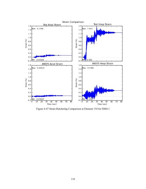
- Page 131 and 132: Figure 4-49 Strain Ratcheting Compa
- Page 133 and 134: Figure 4-51 Strain Ratcheting Compa
- Page 135 and 136: Figure 4-53 Strain Ratcheting Compa
- Page 137 and 138: Figure 4-55 Strain Ratcheting Compa
- Page 139 and 140: Figure 4-57 Strain Ratcheting Compa
- Page 141 and 142: Figure 4-60 Horizontal Input Motion
- Page 143 and 144: Figure 4-62 Displacement D2 Compari
- Page 145 and 146: Figure 4-64 Acceleration A2 Compari
- Page 147 and 148: Figure 4-66 Relative Deformation Hi
- Page 149 and 150: Figure 4-68 Strain Ratcheting Compa
- Page 151 and 152: Figure 4-70 Strain Ratcheting Compa
- Page 153 and 154: described in Sections 4 of this rep
- Page 155 and 156: U.S. Nuclear Regulatory Commission,
- Page 157 and 158: nominal dimensions for the straight
- Page 159 and 160: Figure A-1 Original and Modified Re
- Page 161 and 162: Figure A-5 Ratio of Reaction Forces
- Page 163 and 164: Figure A-9 Ratio of Reaction Force
- Page 165 and 166: Figure A-13 Ratio of Top Half Signi
- Page 167: NRC FORM 335 U.S. NUCLEAR REGULATOR