Seismic Analysis of Large-Scale Piping Systems for the JNES ... - NRC
Seismic Analysis of Large-Scale Piping Systems for the JNES ... - NRC
Seismic Analysis of Large-Scale Piping Systems for the JNES ... - NRC

You also want an ePaper? Increase the reach of your titles
YUMPU automatically turns print PDFs into web optimized ePapers that Google loves.
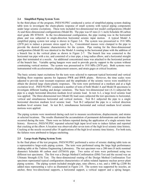
2.4 Simplified <strong>Piping</strong> System Tests<br />
In <strong>the</strong> third phase <strong>of</strong> <strong>the</strong> program, <strong>JNES</strong>/NUPEC conducted a series <strong>of</strong> simplified piping system shaking<br />
table tests to investigate <strong>the</strong> elasto-plastic response <strong>of</strong> small systems with typical piping components<br />
under large seismic excitations. These tests included two-dimensional test model configurations (Model<br />
A) and three-dimensional configurations (Model B). The pipe was 65 mm (2-½ inch) Schedule 40 carbon<br />
steel grade JIS STS410. In <strong>the</strong> two-dimensional configuration, <strong>the</strong> pipe routing was in <strong>the</strong> horizontal<br />
plane and was subjected to single-direction horizontal seismic input motion. A typical Model A<br />
simplified piping system test setup is shown in Figure 2-6. The system was pressurized to 19.8 MPa<br />
(2870 psi) to induce a pressure stress equal to Sm. Concentrated masses were clamped to <strong>the</strong> pipe to<br />
provide <strong>the</strong> desired dynamic characteristics <strong>for</strong> <strong>the</strong> system. Pipe routing <strong>for</strong> <strong>the</strong> three-dimensional<br />
configuration (Model B) was identical to <strong>the</strong> Model A routing in <strong>the</strong> horizontal plane with <strong>the</strong> addition <strong>of</strong><br />
a branch line in <strong>the</strong> vertical plane as shown in Figure 2-7. The branch line was connected to <strong>the</strong><br />
horizontal run pipe with a tee, and consisted <strong>of</strong> a riser pipe, a long radius elbow, and a horizontal straight<br />
pipe that terminated at a nozzle. An additional concentrated mass was attached to <strong>the</strong> horizontal portion<br />
<strong>of</strong> <strong>the</strong> branch line. Variable spring hangers were used to provide gravity support to <strong>the</strong> system without<br />
constraining vertical motion. The system was pressurized to 19.8 MPa (2870 psi). Both systems were<br />
instrumented with accelerometers, displacement sensors, and strain gages at critical locations.<br />
The basic seismic input excitations <strong>for</strong> <strong>the</strong> tests were selected to represent typical horizontal and vertical<br />
building floor response spectra <strong>for</strong> Japanese PWR and BWR plants. However, <strong>the</strong> time scales were<br />
adjusted to provide near resonant responses and <strong>the</strong> amplitudes <strong>of</strong> <strong>the</strong> seismic waves were modified to<br />
obtain <strong>the</strong> desired large elasto-plastic responses. The tests were per<strong>for</strong>med at a medium and at a high<br />
excitation level. <strong>JNES</strong>/NUPEC conducted a number <strong>of</strong> tests <strong>of</strong> both Model A and Model B specimens to<br />
investigate different loading and design variations. The basic two-dimensional test (A-1) subjected <strong>the</strong><br />
pipe to a single horizontal direction medium level seismic load. In test A-2, a large level seismic load<br />
was applied. The three-dimensional test (Model B) load cases subjected <strong>the</strong> test specimens to horizontal,<br />
vertical and simultaneous horizontal and vertical motions. Test B-1 subjected <strong>the</strong> pipe to a single<br />
horizontal direction medium level seismic load. Test B-2 subjected <strong>the</strong> pipe to a vertical direction<br />
medium level seismic load. In test B-3, simultaneous horizontal and vertical medium level seismic<br />
motions were applied.<br />
The piping systems were monitored during each test to measure accelerations, displacements, and strains<br />
at selected locations. The results illustrated <strong>the</strong> accumulation <strong>of</strong> permanent de<strong>for</strong>mations and strains that<br />
occurred during <strong>the</strong> tests. There were no failures reported during <strong>the</strong> application <strong>of</strong> a single seismic time<br />
history. However, <strong>JNES</strong>/NUPEC repeated selected high input level tests to induce failure and reported<br />
that cracking at <strong>the</strong> elbow A location was observed after seven tests <strong>of</strong> <strong>the</strong> high level seismic time history.<br />
Cracking at <strong>the</strong> nozzle occurred after 18 applications <strong>of</strong> <strong>the</strong> high level seismic time history. For both tests,<br />
<strong>the</strong> failures were attributed to fatigue ratcheting.<br />
2.5 <strong>Large</strong>-<strong>Scale</strong> <strong>Piping</strong> System Tests<br />
In <strong>the</strong> final phase <strong>of</strong> <strong>the</strong> test program, <strong>JNES</strong>/NUPEC per<strong>for</strong>med a series <strong>of</strong> seismic shaking table tests on<br />
a representative large-scale piping system. The tests were per<strong>for</strong>med using <strong>the</strong> large high per<strong>for</strong>mance<br />
shaking table at <strong>the</strong> Tadotsu Engineering Laboratory. The test specimen was a 200 mm (8 inch) nominal<br />
diameter) Schedule 40 carbon steel (STS410) pipe. Two series <strong>of</strong> tests were per<strong>for</strong>med using two<br />
different test specimens. The first was a Design Method Confirmation (DM) Test and <strong>the</strong> second was an<br />
Ultimate Strength (US) Test. The three-dimensional routing <strong>of</strong> <strong>the</strong> Design Method Confirmation Test<br />
specimen represented typical configuration characteristics <strong>of</strong> safety-related Japanese nuclear power plant<br />
piping systems. The piping system included straight pipe, nine elbows, a tee, and a 1000 kg (2200 lb)<br />
added mass representing a valve as illustrated in Figure 2-8. The system was supported by nozzles, an<br />
anchor, three two-directional supports, a horizontal support, a vertical support and a spring hanger.<br />
4