Start-Up, Operation, and Maintenance Instructions - Carrier
Start-Up, Operation, and Maintenance Instructions - Carrier
Start-Up, Operation, and Maintenance Instructions - Carrier
You also want an ePaper? Increase the reach of your titles
YUMPU automatically turns print PDFs into web optimized ePapers that Google loves.
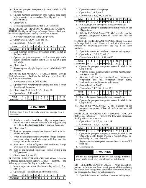
4. <strong>Start</strong> the pumpout compressor (control switch at ON<br />
position).<br />
5. Operate pumpout compressor until suction gage reads<br />
highest sustained vacuum (about 28 in. Hg VAC or 1<br />
psia [6.9 kPa]).<br />
6. Close valve 8.<br />
7. Stop compressor (control switch at OFF position).<br />
REMOVE AIR AFTER OPENING CHILLER TO ATMO-<br />
SPHERE (Refrigerant Charge in Storage Tank) — Perform<br />
the following procedure. See Fig. 4 for valve numbers.<br />
1. Place the control switch in the OFF position.<br />
2. Close valves 2, 4, 5, 9, 10, 11 <strong>and</strong> 13.<br />
3. Open valves 1, 3, 6, 7, 8, <strong>and</strong> 12.<br />
Valve 1 2 3 4 5 6 7 8 9 10 11 12 13<br />
Condition O C O C C O O O C C C O C<br />
4. <strong>Start</strong> pumpout compressor by putting control switch in<br />
the ON position.<br />
5. Operate pumpout compressor until suction gage reads<br />
highest sustained vacuum (about 28 in. hg or 1 psia<br />
[6.9 kPa]).<br />
6. Close valve 8.<br />
7. Stop compressor by placing the control switch in the OFF<br />
position.<br />
TRANSFER REFRIGERANT CHARGE (From Storage<br />
Tank to Machine) — Perform the following procedure. See<br />
Fig. 4 for valve numbers.<br />
1. Place control switch in OFF position.<br />
2. Operate cooler water pump <strong>and</strong> ensure that there is water<br />
flow through the cooler.<br />
3. Close valves 2, 4, 5, 6, 7, 8, 9, 10, <strong>and</strong> 11.<br />
4. Open valves 1, 3, 12, <strong>and</strong> 13.<br />
Valve 1 2 3 4 5 6 7 8 9 10 11 12 13<br />
Condition O C O C C C C C C C C O O<br />
CAUTION<br />
Follow steps 5 <strong>and</strong> 6 carefully to prevent damage from a<br />
freeze-up.<br />
5. Slowly open valve 5 <strong>and</strong> allow refrigerant vapor into the<br />
chiller until chiller pressure increases to 35 psig (141 kPa)<br />
for R-134a. Feed refrigerant slowly to avoid freeze-up.<br />
6. Close valve 5.<br />
7. <strong>Start</strong> the pumpout compressor (control switch in the<br />
AUTO position).<br />
8. When the cooler pressure is lower than storage tank pressure,<br />
open valve 11 <strong>and</strong> refrigerant will flow from the<br />
storage tank to the machine.<br />
9. Shut valve 11 when refrigerant level reaches the charge<br />
level mark on the cooler sight glass.<br />
10. Turn off the pumpout compressor (control switch in the<br />
OFF position).<br />
11. Close valves 3, 4, <strong>and</strong> 12.<br />
TRANSFER REFRIGERANT CHARGE (From Machine<br />
to Storage Tank Located Below Machine) — Perform the<br />
following procedure. See Fig. 4 for valve numbers.<br />
1. Vent storage tank to machine by opening valves 1, 2, 4,<br />
<strong>and</strong> 12.<br />
2. Open valves 11 <strong>and</strong> drain liquid from the cooler.<br />
Valve 1 2 3 4 5 6 7 8 9 10 11 12 13<br />
Condition O O C O C C C C C C O O C<br />
12<br />
3. Operate the cooler water pump.<br />
4. Open valves 3, 6, 7, <strong>and</strong> 9.<br />
5. Close valves 2, 4, 5, 10 ,11, <strong>and</strong> 13.<br />
Valve 1 2 3 4 5 6 7 8 9 10 11 12 13<br />
Condition O C O C C O O C O C C O C<br />
6. Run cooling water through the pumpout condenser.<br />
7. Operate the pumpout compressor (control switch in the<br />
ON position).<br />
8. At 25 in. Hg VAC (2.5 psia, 17.21 kPa) in cooler, stop the<br />
pumpout compressor. Close all valves <strong>and</strong> shut off<br />
pumps.<br />
TRANSFER REFRIGERANT CHARGE (From Machine<br />
to Storage Tank Located Above or Level with Machine) —<br />
Perform the following procedure. See Fig. 4 for valve<br />
numbers.<br />
1. Operate the cooler <strong>and</strong> machine condenser water pumps.<br />
2. Open valves 1, 2, 5, 6, 7, <strong>and</strong> 12.<br />
3. Close valves 3, 4, 8, 9, 10 ,11, <strong>and</strong> 13.<br />
Valve 1 2 3 4 5 6 7 8 9 10 11 12 13<br />
Condition O O C C O O O C C C C O C<br />
4. Operate the pumpout compressor (control switch in the<br />
ON position).<br />
5. When the storage tank pressure is less than machine pressure,<br />
open valve 11.<br />
6. After the liquid has been transferred, stop the pumpout<br />
compressor <strong>and</strong> the condenser water pump.<br />
Continue to operate the cooler water pump.<br />
7. Open valves 3, 6, 7 <strong>and</strong> 9.<br />
8. Close valves 2, 4, 5, 10, 11, <strong>and</strong> 13.<br />
Valve 1 2 3 4 5 6 7 8 9 10 11 12 13<br />
Condition O C O C C O O C O C C O C<br />
9. Run cooling water through the pumpout condenser.<br />
10. Operate the pumpout compressor (control switch in the<br />
ON position).<br />
11. At 25 in. Hg VAC (2.5 psia, 17.21 kPa) in cooler, stop the<br />
pumpout compressor. Close all valves <strong>and</strong> shut off<br />
pumps.<br />
PRESSURIZE MACHINE AND STORAGE TANK (No<br />
Refrigerant in System) — Perform the following procedure.<br />
See Fig. 4 for valve numbers.<br />
1. Open valves 3, 4, 6, 7, 9, 11, <strong>and</strong> 13.<br />
2. Close valves 1, 2, 5, 8, 10 , <strong>and</strong> 12.<br />
Valve 1 2 3 4 5 6 7 8 9 10 11 12 13<br />
Condition C C O O C O O C O C O C O<br />
3. Operate the pumpout compressor (control switch in the<br />
ON position) until desired pressure is reached. Do not exceed<br />
design pressure of vessels.<br />
4. Stop the pumpout compressor (control switch in the OFF<br />
position).<br />
5. Close valve 13.<br />
WARNING<br />
Do not use refrigerant or air for leak testing. Personal<br />
injury could result. Only use nitrogen for leak testing.<br />
DISTILL REFRIGERANT CHARGE — Water, oil, <strong>and</strong> impurities<br />
can be removed from the refrigerant while transferring<br />
the charge from storage tank to machine. Perform the following<br />
procedure. See Fig. 4 for valve numbers.<br />
1. Operate the cooler <strong>and</strong> machine condenser water pumps.


