

Start-Up, Operation, and Maintenance Instructions - Carrier
Start-Up, Operation, and Maintenance Instructions - Carrier
Start-Up, Operation, and Maintenance Instructions - Carrier

You also want an ePaper? Increase the reach of your titles
YUMPU automatically turns print PDFs into web optimized ePapers that Google loves.
efrigerant side of the seal <strong>and</strong> the oil supply being controlled<br />
by the differential pressure regulator. The pressure being supplied<br />
to the seal is maintained at 35 psid above the pressure on<br />
the refrigerant side of the shaft seal. The auxiliary oil pump<br />
should start if the differential pressure falls to or below 23 psid.<br />
Lower the oil pressure by adjusting the differential oil pressure<br />
regulator until the oil pressure drops to 23 psid. On completion<br />
of the test, reset the oil pressure regulator to its normal<br />
setting of 35 psid. The auxiliary pump will stop when the oil<br />
pressure rises above 27 psid.<br />
CHECK SEAL OIL DIFFERENTIAL PRESSURE<br />
TRANSDUCER — This function shuts down the compressor<br />
if the seal oil pressure differential drops below its fault limit.<br />
The transducer should be checked for proper calibration by<br />
comparing against a known pressure gage. If two individual<br />
single input transducers are used instead of a differential transducer,<br />
the measured pressures will be compared by the PLC to<br />
calculate the differential pressure reading.<br />
CHECK THRUST BEARING OIL PRESSURE TRANS-<br />
DUCER — This function shuts down the compressor if the<br />
thrust bearing oil pressure drops below its fault limit. The thrust<br />
bearing is in the ambient atmosphere so the oil pressure is referenced<br />
to ambient pressure. The transducer should be checked<br />
for proper calibration by comparing against a known pressure<br />
gage <strong>and</strong> the set point should be checked on the PLC screen.<br />
CHECK DISCHARGE GAS HIGH-TEMPERATURE<br />
CUTOUT — This function shuts down the compressor if the<br />
compressor discharge gas temperature exceeds its fault limit.<br />
The sensor is located in a temperature well in the back wall of<br />
the compressor. It is located to the immediate right of the bearing<br />
chamber on the 7 frame compressor <strong>and</strong> to the immediate<br />
left of the bearing chamber on the 8 frame compressor. The<br />
sensor should be compared against a calibrated sensor in a calibration<br />
bath or dry block calibrator.<br />
CHECK THRUST BEARING OIL HIGH-TEMPERA-<br />
TURE CUTOUT — This function shuts down the compressor<br />
if the temperature of the oil leaving the compressor exceeds its<br />
fault limit. The sensor is located in the bearing chamber <strong>and</strong> is<br />
inserted into the leaving oil temperature well that is an integral<br />
part of the thrust bearing housing.<br />
The sensor should be compared against a calibrated sensor<br />
in a calibration bath or dry block calibrator.<br />
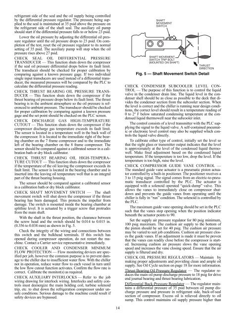
CHECK SHAFT MOVEMENT SWITCH — The shaft<br />
movement switch will shut down the compressor if the thrust<br />
bearing has been damaged. This protects the impeller from<br />
damage. The switch is mounted inside the bearing chamber at<br />
splitline level. It is actuated by a trigger screw that protrudes<br />
from the main shaft.<br />
With the shaft in the thrust position, the clearance between<br />
the screw head <strong>and</strong> the switch should be 0.014 to 0.015 in.<br />
(0.356 to 0.038 mm) as shown in Fig. 5.<br />
Check the integrity of the wiring <strong>and</strong> connections between<br />
this switch <strong>and</strong> the bulkhead terminals. If this switch has<br />
opened during compressor operation, do not restart the machine.<br />
Contact a <strong>Carrier</strong> service representative immediately.<br />
CHECK COOLER AND CONDENSER MINIMUM<br />
FLOW PROTECTION — Flow monitoring devices are specified<br />
per job, however the common purpose is to prevent damage<br />
to the chiller due to insufficient water flow. With the chiller<br />
not in operation, reduce water flow to each vessel in turn until<br />
the low flow cutout function activates. Confirm the flow rate is<br />
correct. Calibrate the monitor(s) as required.<br />
CHECK AUXILIARY INTERLOCKS — Refer to the job<br />
wiring drawing for interlock wiring. Interlocks <strong>and</strong> safety controls<br />
must deenergize the main holding coil, turbine solenoid<br />
trip, etc. to shut down the refrigeration compressor under unsafe<br />
conditions. Serious damage to the machine could result if<br />
safety devices are bypassed.<br />
14<br />
a17-574<br />
Fig. 5 — Shaft Movement Switch Detail<br />
CHECK CONDENSER SUBCOOLER LEVEL CON-<br />
TROL — The purpose of this function is to control the liquid<br />
valve in the condenser drain line. The liquid level in the condenser<br />
shell should be as close as possible to the deck that divides<br />
the condenser section from the subcooler section. When<br />
the level is correct <strong>and</strong> the chiller is running near design conditions,<br />
the correct level should result in a temperature reading of<br />
0 to 2° F below saturated condensing temperature at the condensed<br />
liquid thermowell near the subcooler inlet.<br />
The control consists of a level transmitter with the PLC supplying<br />
the signal to the liquid valve. A self-contained pneumatic<br />
or electronic level control may also be supplied which controls<br />
the liquid valve directly.<br />
To calibrate either type of control, initially set the level so<br />
that the sight glass or transmitter output indicates that the level<br />
is approximately at the level of the condensed liquid thermowell.<br />
Make final adjustment based on the condensed liquid<br />
temperature. If the temperature is too low, drop the level. If the<br />
temperature is too high, raise the level.<br />
CHECK COMPRESSOR GUIDE VANE CONTROL —<br />
The st<strong>and</strong>ard guide vane actuator is a pneumatic piston actuator<br />
controlled by a built-in positioner. The positioner receives a<br />
3 to 15 psig signal. The signal comes from an electric-to-pneumatic<br />
transducer controlled by the PLC. The actuator is<br />
equipped with a solenoid operated “quick-dump” valve. This<br />
allows the vanes to immediately close on compressor shutdown<br />
<strong>and</strong> prevents the guide vanes from operating until the<br />
chiller is fully in “run” condition. The solenoid is controlled by<br />
the PLC.<br />
The maximum guide vane opening should be set in the PLC<br />
such that the vanes stop opening when the position indicator<br />
beneath the actuator points to 90.<br />
Set the supply air pressure regulator for 80 psig minimum,<br />
100 psig maximum. The cushion air supply to the bottom of<br />
the piston should be set for 40 psig. The cushion air pressure<br />
may be varied to suit job conditions. Cushion air pressure closes<br />
the guide vanes. If an adjustment is made it must be proven<br />
that the vanes can readily close before the compressor is started.<br />
Increasing cushion air pressure slows the vane opening<br />
speed <strong>and</strong> increases the vane closing speed. Ensure that the air<br />
supply is filtered <strong>and</strong> dry.<br />
CHECK OIL PRESSURE REGULATORS — Maintain by<br />
making proper adjustments <strong>and</strong> providing clean <strong>and</strong> ample oil<br />
supply. See Oil Cycle section on page 18 for more information.<br />
Thrust Bearing Oil Pressure Regulator — The regulator reduces<br />
the main oil pump discharge pressure to 18 psig for drive<br />
end journal bearing <strong>and</strong> thrust bearing lubrication.<br />
Differential Back-Pressure Regulator — The regulator maintains<br />
a differential pressure of 35 psid between oil pump discharge<br />
pressure <strong>and</strong> pressure in refrigerant side, back-of-seal<br />
section of compressor. Excess oil is relieved directly to oil<br />
sump. This control maintains oil supply pressure higher than


