

Start-Up, Operation, and Maintenance Instructions - Carrier
Start-Up, Operation, and Maintenance Instructions - Carrier
Start-Up, Operation, and Maintenance Instructions - Carrier

Create successful ePaper yourself
Turn your PDF publications into a flip-book with our unique Google optimized e-Paper software.
• Controls - Instruments which control the brine temperature,<br />
protect the various elements of the machine, <strong>and</strong> automatically<br />
start <strong>and</strong> stop the compressor. When specified, additional<br />
controls for automatic operation of interconnecting<br />
equipment such as fans <strong>and</strong> pumps are furnished.<br />
• Drive - Prime mover which supplies the power to drive the<br />
compressor.<br />
• A refrigerant pumpout <strong>and</strong> storage unit is usually furnished<br />
with this equipment. The refrigeration cycle covers the first<br />
three major components; the others are described in other<br />
portions of this manual.<br />
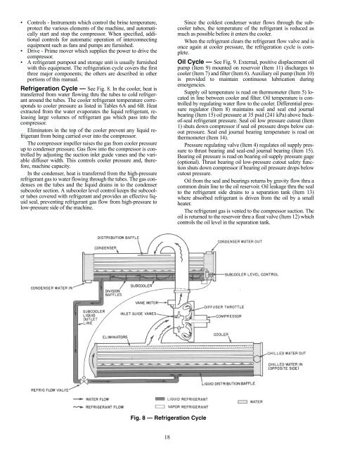
Refrigeration Cycle — See Fig. 8. In the cooler, heat is<br />
transferred from water flowing thru the tubes to cold refrigerant<br />
around the tubes. The cooler refrigerant temperature corresponds<br />
to cooler pressure as listed in Tables 6A <strong>and</strong> 6B. Heat<br />
extracted from the water evaporates the liquid refrigerant, releasing<br />
large volumes of refrigerant gas which pass into the<br />
compressor.<br />
Eliminators in the top of the cooler prevent any liquid refrigerant<br />
from being carried over into the compressor.<br />
The compressor impeller raises the gas from cooler pressure<br />
up to condenser pressure. Gas flow into the compressor is controlled<br />
by adjusting the suction inlet guide vanes <strong>and</strong> the variable<br />
diffuser width. This controls cooler pressure <strong>and</strong>, therefore,<br />
machine capacity.<br />
In the condenser, heat is transferred from the high-pressure<br />
refrigerant gas to water flowing through the tubes. The gas condenses<br />
on the tubes <strong>and</strong> the liquid drains in to the condenser<br />
subcooler section. A subcooler level control keeps the subcooler<br />
tubes covered with refrigerant <strong>and</strong> provides an effective liquid<br />
seal, preventing refrigerant gas flow from high-pressure to<br />
low-pressure side of the machine.<br />
Fig. 8 — Refrigeration Cycle<br />
18<br />
Since the coldest condenser water flows through the subcooler<br />
tubes, the temperature of the refrigerant is reduced as<br />
much as possible before it enters the cooler.<br />
When the refrigerant clears the refrigerant flow valve <strong>and</strong> is<br />
once again at cooler pressure, the refrigeration cycle is complete.<br />
Oil Cycle — See Fig. 9. External, positive displacement oil<br />
pump (Item 9) mounted on reservoir (Item 11) discharges to<br />
cooler (Item 7) <strong>and</strong> filter (Item 6). Auxiliary oil pump (Item 10)<br />
is provided to maintain continuous lubrication during<br />
emergencies.<br />
Supply oil temperature is read on thermometer (Item 5) located<br />
in line between cooler <strong>and</strong> filter. Oil temperature is controlled<br />
by regulating water flow to the cooler. Differential pressure<br />
regulator (Item 8) maintains seal <strong>and</strong> seal end journal<br />
bearing (Item 15) oil pressure at 35 psid (241 kPa) above backof-seal<br />
refrigerant pressure. Seal oil low pressure cutout (Item<br />
1) shuts down compressor if seal oil pressure drops below cutout<br />
pressure. Seal end journal bearing temperature is read on<br />
thermometer (Item 14).<br />
Pressure regulating valve (Item 4) regulates oil supply pressure<br />
to thrust bearing <strong>and</strong> seal-end journal bearing (Item 15).<br />
Bearing oil pressure is read on bearing oil supply pressure gage<br />
(optional). Thrust bearing oil low-pressure cutout safety function<br />
shuts down compressor if bearing oil pressure drops below<br />
cutout pressure.<br />
Oil from the seal <strong>and</strong> bearings returns by gravity flow thru a<br />
common drain line to the oil reservoir. Oil leakage thru the seal<br />
to the refrigerant side drains to a separation tank (Item 13)<br />
where absorbed refrigerant is driven from the oil by a small<br />
heater.<br />
The refrigerant gas is vented to the compressor suction. The<br />
oil is returned to the reservoir thru a float valve (Item 12) which<br />
controls the oil level in the separation tank.<br />
a17-575


