

Start-Up, Operation, and Maintenance Instructions - Carrier
Start-Up, Operation, and Maintenance Instructions - Carrier
Start-Up, Operation, and Maintenance Instructions - Carrier

You also want an ePaper? Increase the reach of your titles
YUMPU automatically turns print PDFs into web optimized ePapers that Google loves.
trip is a good example of the type of safety that acts directly. If<br />
specified, there may be both sensor inputs <strong>and</strong> mechanical<br />
switches monitoring some points.<br />
Refer to Table 1 for set points, except for the settings supplied<br />
with the machine documentation. Job documentation will take<br />
precedence over these st<strong>and</strong>ard settings.<br />
Temperature switches should be set in a temperature bath <strong>and</strong><br />
compared to an accurate st<strong>and</strong>ard or electronic thermometer.<br />
Pressure switches should be set using an accurate gage <strong>and</strong> a<br />
controlled pressure source.<br />
Pressure transducers should be checked using an accurate<br />
gage <strong>and</strong> a controlled pressure source.<br />
Thermistor <strong>and</strong> RTD sensor panel readouts should be compared<br />
to the temperature to which they are exposed. If possible,<br />
hold the sensor in ambient air <strong>and</strong> compare the reading with an<br />
accurate thermometer.<br />
Mechanical interlock <strong>and</strong> limit switch operation must be confirmed<br />
by testing the actuator.<br />
The turbine overspeed linkage should be tested before the turbine<br />
is powered. The trip actuator in the shaft can only be tested<br />
by running the turbine. Once the turbine can run, it should be<br />
gradually brought up to trip speed. If the turbine fails to trip at<br />
the trip speed, then it should be shut down immediately <strong>and</strong> not<br />
be started until a turbine manufacturer’s representative corrects<br />
the problem.<br />
Motor Drive — Accurate communication between the controls<br />
<strong>and</strong> the starter/VFD (variable frequency drive) must be confirmed<br />
by test. For equipment of the size <strong>and</strong> capacity of the<br />
17DA chiller, it is likely that the control panel <strong>and</strong> the starter/<br />
VFD will communicate through a data line, not through hardwired<br />
circuits. There may be an “Emergency Stop” button hardwired<br />
between the control panel <strong>and</strong> the starter.<br />
Where the chiller controls <strong>and</strong> ancillary equipment controls<br />
are connected to a building automation system via data lines, it<br />
must be confirmed that the central system cannot override the<br />
chiller safeties nor energize any chiller component directly. The<br />
starter or VFD, in particular, must be protected from being energized<br />
by a comm<strong>and</strong> from anywhere other than the chiller controls.<br />
With the starter in a safety mode or disconnected from the<br />
motor, attempts to energize the starter should be made from the<br />
building controls to confirm that the building control system cannot<br />
energize the starter directly.<br />
If the starter can be energized, reprogramming of the control<br />
system is essential before the starter is put on-line. Accidental<br />
starting of the motor could have extreme consequences to the<br />
chiller.<br />
The program correction should be made in the starter/VFD<br />
control system rather than in the building control system so that<br />
future updates to the building controls do not remove this<br />
protection.<br />
4<br />
Gas Engine Drive — Engine drives will be tested <strong>and</strong><br />
started by the engine manufacturer's representative. Control interfaces<br />
will be tested by the <strong>Carrier</strong> technician in co-operation<br />
with the engine manufacturer's representative. A check list from<br />
the engine manufacturer must be completed before the engine<br />
service representative is called.<br />
Turbine Drive — Turbines have their own safety systems<br />
which should be tested according to the instructions found in<br />
their manufacturer’s literature. If the manufacturer’s instructions<br />
are not available, they must be obtained from the local <strong>Carrier</strong><br />
representative or from the turbine manufacturer.<br />
Interlocks between the chiller controls <strong>and</strong> the turbine controls<br />
must be tested. The chiller must energize a solenoid which<br />
then allows the trip <strong>and</strong> throttle valve to be set. If the solenoid is<br />
deenergized, then the turbine trip <strong>and</strong> throttle valve must immediately<br />
close.<br />
A feedback switch to the chiller controls is located on the trip<br />
<strong>and</strong> throttle valve. The switch must close when the valve is<br />
opened. This provides a RUN signal to the chiller controls which<br />
will then start to load the compressor. If the trip <strong>and</strong> throttle<br />
valve is closed by a trip from either the chiller or turbine controls,<br />
then this switch will open. This is a signal to the chiller that<br />
the turbine has tripped <strong>and</strong> the chiller will enter a safety shutdown<br />
mode.<br />
Other interlocks, signals <strong>and</strong> feedbacks will vary with the job.<br />
Consult the job controls manual <strong>and</strong> the field control drawings<br />
for the entire chiller <strong>and</strong> for the turbine.<br />
All items on Pre-<strong>Start</strong>-<strong>Up</strong> Checklist must be completed before<br />
the turbine service representative is called.<br />
Pumpout System — The low-pressure cutout should be<br />
set at the saturated pressure of refrigerant R-134a at 34 F (1 C).<br />
A manual bypass switch is required to allow complete evacuation<br />
of the cooler. See Table 2.<br />
Leak Test <strong>and</strong> Dehydration — Check the absolute<br />
pressure on the refrigerant side of the machine. The final operation<br />
of the 17DA installation is to leak test the machine <strong>and</strong> dehydrate<br />
it to the point where it maintains a pressure of 0.21 psia<br />
(1 kPa) (equivalent to 29.48 in. [749 mm] mercury vacuum referenced<br />
to a 30 in. [762 mm] barometer). Refer to the Leak Testing<br />
<strong>and</strong> Chiller Dehydration sections on pages 15 <strong>and</strong> 16.<br />
If the machine absolute pressure is higher than the above values,<br />
repeat the evacuation <strong>and</strong> dehydration pumpdown operations<br />
until the machine proves to have a leak rate or vacuum loss<br />
at a rate less than 0.1 in. (2 mm) mercury column in 24 hours.<br />
The oil will always contain a minimal amount of dissolved<br />
refrigerant. It is normal for a refrigerant sensor to sense refrigerant<br />
if placed too near the vent caps. If the seal allows refrigerant<br />
vapor to pass, a sensor located at floor level 3 to 4 ft (0.9 to<br />
1.2 m) from the sump vent cap will be quickly triggered as the<br />
heavy refrigerant vapor will drop into the sump <strong>and</strong> flow out the<br />
vent cap to floor level.<br />
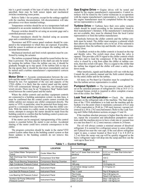
Table 1 — Control Settings<br />
CONTROL LOCATION<br />
English<br />
SETTING<br />
Metric<br />
Low Chilled Water Temperature<br />
Cutout<br />
Cooler Water Box<br />
36 F or 5 F lower than brine temperature<br />
2.2 C or 3 C lower than brine temperature<br />
High Discharge Gas Temperature<br />
Cutout<br />
Compressor End Wall 220 F 104 C<br />
High Thrust Bearing Temperature Compressor Bearing Chamber 185 F 85 C<br />
High Condenser Pressure Cutout Instrument Panel 185 psig 13.0 kg/sq cm<br />
Low Cooler Pressure Cutout Instrument Panel<br />
2 psi below design suction<br />
pressure<br />
0.14 kg/sq cm<br />
Low Seal Oil Pressure Cutout Instrument Panel Trip 11 psid Trip 0.76 kg/sq cm<br />
Low Bearing Oil Pressure Cutout Instrument Panel<br />
Trip 8 psig<br />
Reset 13 psig<br />
Trip 0.56 kg/sq cm<br />
Reset 0.90 kg/sq cm<br />
Auxiliary Oil Pump Differential<br />
Pressure Control<br />
Instrument Panel<br />
Stop 27 psid<br />
<strong>Start</strong> 23 psid<br />
Stop 1.90 kg/sq cm<br />
<strong>Start</strong> 1.60 kg/sq cm


