The design report
The design report
The design report

You also want an ePaper? Increase the reach of your titles
YUMPU automatically turns print PDFs into web optimized ePapers that Google loves.
Landing gear geometry 3.1.7<br />
Landing gear <strong>design</strong> initiated with the decision that a quadricycle configuration would<br />
be used for this twin fuselage <strong>design</strong> as it has been used historically with great success<br />
for similar <strong>design</strong>s. <strong>The</strong> quadricycle <strong>design</strong> consists of 4 landing gears in total, with two<br />
nose gears and two rear or main gears. <strong>The</strong> four wheels usually take off at the same time<br />
with both the front gears being used to control direction of aircraft with the help of<br />
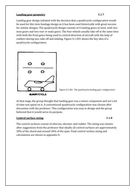
rudders during taxi, take off and landing. Figure 4.1.501 shows the key idea of a<br />
quadricycle configuration.<br />
Figure 4.1.501- <strong>The</strong> quadricycle landing gear configuration<br />
At that stage, the group thought that landing gear was a minor component and not a lot<br />
of time was spent on it. A conventional quadricycle configuration was chosen after<br />
discussion with the professor. This configuration was easy to <strong>design</strong> and the group<br />
believed that it would serve its purpose.<br />
Control surface sizing 3.1.8<br />
<strong>The</strong> control surfaces consist of ailerons, elevator and rudder. <strong>The</strong> sizing was chosen<br />
after suggestions from the professor that ideally all control surfaces are approximately<br />
30% of the chord and around 30% of the span. Final control surface sizing and<br />
calculations are shown in appendix D.


![Introduction to RF Stealth [Book Review] - Antennas and ...](https://img.yumpu.com/16857890/1/190x245/introduction-to-rf-stealth-book-review-antennas-and-.jpg?quality=85)