The design report
The design report
The design report

Create successful ePaper yourself
Turn your PDF publications into a flip-book with our unique Google optimized e-Paper software.
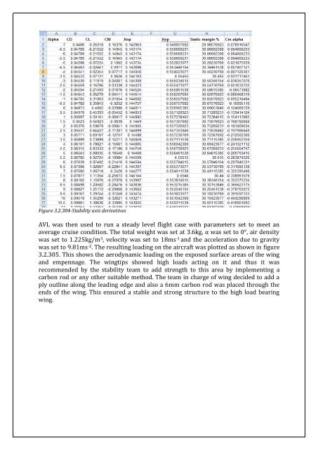
Figure 3.2.304-Stability axis derivatives<br />
AVL was then used to run a steady level flight case with parameters set to meet an<br />
average cruise condition. <strong>The</strong> total weight was set at 3.6kg, α was set to 0°, air density<br />
was set to 1.225kg/m 3 , velocity was set to 18ms -1 and the acceleration due to gravity<br />
was set to 9.81ms -2 . <strong>The</strong> resulting loading on the aircraft was plotted as shown in figure<br />
3.2.305. This shows the aerodynamic loading on the exposed surface areas of the wing<br />
and empennage. <strong>The</strong> wingtips showed high loads acting on it and thus it was<br />
recommended by the stability team to add strength to this area by implementing a<br />
carbon rod or any other suitable method. <strong>The</strong> team in charge of wing decided to add a<br />
ply outline along the leading edge and also a 6mm carbon rod was placed through the<br />
ends of the wing. This ensured a stable and strong structure to the high load bearing<br />
wing.

![Introduction to RF Stealth [Book Review] - Antennas and ...](https://img.yumpu.com/16857890/1/190x245/introduction-to-rf-stealth-book-review-antennas-and-.jpg?quality=85)