2001-01-0595 A Model-Based Brake Pressure Estimation ... - Delphi
2001-01-0595 A Model-Based Brake Pressure Estimation ... - Delphi
2001-01-0595 A Model-Based Brake Pressure Estimation ... - Delphi

Create successful ePaper yourself
Turn your PDF publications into a flip-book with our unique Google optimized e-Paper software.
SAE TECHNICAL<br />
PAPER SERIES <strong>20<strong>01</strong></strong>-<strong>01</strong>-<strong>0595</strong><br />
A <strong>Model</strong>-<strong>Based</strong> <strong>Brake</strong> <strong>Pressure</strong> <strong>Estimation</strong><br />
Strategy for Traction Control System<br />
Qingyuan Li, Keith W. Beyer and Quan Zheng<br />
<strong>Delphi</strong> Automotive Systems<br />
Reprinted From: <strong>Brake</strong> Technology, ABS/TCS, and Controlled Suspensions<br />
(SP–1576)<br />
SAE <strong>20<strong>01</strong></strong> World Congress<br />
Detroit, Michigan<br />
March 5-8, <strong>20<strong>01</strong></strong><br />
400 Commonwealth Drive, Warrendale, PA 15096-00<strong>01</strong> U.S.A. Tel: (724) 776-4841 Fax: (724) 776-5760
The appearance of this ISSN code at the bottom of this page indicates SAE’s consent that copies of the<br />
paper may be made for personal or internal use of specific clients. This consent is given on the condition,<br />
however, that the copier pay a $7.00 per article copy fee through the Copyright Clearance Center, Inc.<br />
Operations Center, 222 Rosewood Drive, Danvers, MA <strong>01</strong>923 for copying beyond that permitted by Sections<br />
107 or 108 of the U.S. Copyright Law. This consent does not extend to other kinds of copying such as<br />
copying for general distribution, for advertising or promotional purposes, for creating new collective works,<br />
or for resale.<br />
SAE routinely stocks printed papers for a period of three years following date of publication. Direct your<br />
orders to SAE Customer Sales and Satisfaction Department.<br />
Quantity reprint rates can be obtained from the Customer Sales and Satisfaction Department.<br />
To request permission to reprint a technical paper or permission to use copyrighted SAE publications in<br />
other works, contact the SAE Publications Group.<br />
No part of this publication may be reproduced in any form, in an electronic retrieval system or otherwise, without the prior written<br />
permission of the publisher.<br />
ISSN <strong>01</strong>48-7191<br />
Copyright <strong>20<strong>01</strong></strong> Society of Automotive Engineers, Inc.<br />
Positions and opinions advanced in this paper are those of the author(s) and not necessarily those of SAE. The author is solely<br />
responsible for the content of the paper. A process is available by which discussions will be printed with the paper if it is published in<br />
SAE Transactions. For permission to publish this paper in full or in part, contact the SAE Publications Group.<br />
Persons wishing to submit papers to be considered for presentation or publication through SAE should send the manuscript or a 300<br />
word abstract of a proposed manuscript to: Secretary, Engineering Meetings Board, SAE.<br />
Printed in USA<br />
All SAE papers, standards, and selected<br />
books are abstracted and indexed in the<br />
Global Mobility Database
<strong>20<strong>01</strong></strong>-<strong>01</strong>-<strong>0595</strong><br />
A <strong>Model</strong>-<strong>Based</strong> <strong>Brake</strong> <strong>Pressure</strong> <strong>Estimation</strong> Strategy for<br />
Traction Control System<br />
Copyright © <strong>20<strong>01</strong></strong> Society of Automotive Engineers, Inc.<br />
ABSTRACT<br />
This paper presents a brake pressure estimation algorithm<br />
for <strong>Delphi</strong> Traction Control Systems (TCS). A control<br />
oriented lumped parameter model of a brake control<br />
system is developed using Matlab/Simulink. The model is<br />
derived based on a typical brake system and is generic to<br />
other types of brake control hardware systems. For<br />
application purposes, the model is simplified to capture<br />
the dominant dynamic brake pressure response. Vehicle<br />
experimental data collected under various scenarios are<br />
used to validate the algorithm. Simulation results show<br />
that the algorithm gives accurate pressure estimation. In<br />
addition, the calibration procedure is greatly simplified<br />
INTRODUCTION<br />
Traction control plays an important role in improving<br />
vehicle stability during vehicle acceleration. This is<br />
achieved by controlling brake pressure and engine torque<br />
together to reduce the wheel spin. During TCS brake<br />
pressure information is used to determine the torque<br />
reduction required by the engine. It is also used to prevent<br />
over heating of the base brake system during controlled<br />
brake events. Thus, brake pressure is valuable information<br />
needed to improve the safety of the vehicle. However, few<br />
vehicles install brake pressure sensors since it increases<br />
the cost and requires additional diagnostic algorithms [1].<br />
Therefore, an estimation algorithm is required to provide<br />
the brake pressure information.<br />
The current pressure estimation algorithm relies on<br />
numerous of vehicle tests to determine the calibration<br />
values. In an effort to improve the accuracy of brake<br />
pressure estimation, reduce complexity of calibration and<br />
save the calibration time, the model-based brake pressure<br />
estimation strategy was developed. In this paper, a control<br />
oriented lumped parameter model of a brake control<br />
system is developed based on one channel hydraulic<br />
brake system. For production implementation purposes,<br />
Qingyuan Li, Keith W. Beyer and Quan Zheng<br />
<strong>Delphi</strong> Automotive Systems<br />
the higher order dynamics of the algorithm are ignored in<br />
this physical model, and it is simplified to capture the<br />
dominant dynamic brake pressure response. In order to<br />
verify the simplified model, vehicle experimental data<br />
collected under various conditions was used.<br />
This paper outlines and describes the derivation of the<br />
algorithm and presents the simulation results to show that<br />
the algorithm gives accurate pressure estimation.<br />
MODEL FOR TCS BRAKE PRESSURE<br />
CONTROL SYSTEM<br />
There are two types of disc brake calipers in current base<br />
brake products. One is the fixed-caliper disc brake, where<br />
two pistons are used to press the brake pad against the<br />
disc from opposite directions, and the other is the floatingcaliper<br />
disc brake, where only a single piston is used to<br />
press the brake pads against the disc [2].<br />
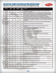
Figure 1 shows the model schematic of the brake<br />
pressure control system for one simplified channel when it<br />
is in traction control mode. The figure shows a motor, a<br />
pump, an accumulator, an orifice, a pressure relief valve,<br />
two solenoid valves labeled as a pressure apply valve and<br />
pressure release valve, brake caliper and pad. The<br />
pressure apply and release valves are represented by an<br />
orifice and the corresponding control command. The<br />
motor drives the pump. The accumulator and orifice<br />
smooth the pressure transients. A pressure relief valve<br />
provides safety to the system. In traction control mode,<br />
the pressure generated by the pump is always higher than<br />
the setting of the pressure relief valve, so the relief valve is<br />
at work all the time. Therefore, the pressure labeled as s P<br />
in Figure 1 can be assumed a constant, which is equal to<br />
the setting of the relief valve. The pressure apply valve is<br />
normally open, and the pressure release valve normally<br />
closed. When the control command is in “APPLY” mode,<br />
the fluid from the pump flows through the apply valve’s
orifice with flow area a 1 , and enters the caliper’s chamber<br />
to build up pressure P c so as to move the brake pad. At<br />
the same time, the release valve is closed. When the<br />
control command is in “RELEASE” mode, the fluid from<br />
the caliper chamber flows through the release valve’s<br />
orifice with flow area a 2 , and goes back to the tank. In<br />
this mode, the apply valve is closed. A third state is the<br />
“HOLD” mode, which is when both apply and release<br />
valves are closed. The brake pad is modeled by a mass,<br />
spring and damper system.<br />
<strong>Pressure</strong> Relief Valve<br />
M<br />
P s<br />
a 1<br />
Apply<br />
command<br />
Q 1<br />
Release<br />
command<br />
Q 2<br />
a 2<br />
V 0<br />
P c<br />
Caliper<br />
Piston x p<br />
Figure 1 <strong>Model</strong> schematic of one simplified channel<br />
hydraulic-mechanical schematic of the brake pressure<br />
control system<br />
To summarize, the symbols used in Figure 1 are defined<br />
as follows:<br />
P s hydraulic line pressure<br />
P c caliper chamber pressure<br />
x p caliper piston displacement<br />
V o initial chamber volume<br />
Q 1 flow rate from apply valve<br />
Q 2 flow rate from release valve<br />
a 1 orifice area for apply valve<br />
a 2 orifice area for release valve<br />
K p<br />
B p<br />
a p caliper piston area<br />
M p mass of the piston<br />
B p damping coefficient<br />
K p effective spring constant<br />
MATHAMATICAL MODEL<br />
From Figure 1, the mathematical model of TCS brake<br />
pressure control system is described by the following<br />
equations [3][4].<br />
M ⋅ x + B ⋅ x + K ⋅ x = P ⋅ a − F<br />
(1)<br />
p<br />
⋅⋅<br />
p<br />
Q −Q<br />
p<br />
⋅<br />
p<br />
V<br />
+<br />
p<br />
p<br />
+ V<br />
β<br />
c<br />
dPc<br />
⋅<br />
dt<br />
⋅<br />
c o<br />
1 2 = a p ⋅ xp<br />
(2)<br />
V a ⋅ x<br />
c<br />
Q<br />
Q<br />
1<br />
= (3)<br />
p<br />
p<br />
2 ⋅(<br />
Ps<br />
− Pc<br />
)<br />
= Cd<br />
⋅ a1<br />
⋅<br />
(4)<br />
ρ<br />
= C<br />
⋅ a<br />
⋅<br />
2⋅<br />
Pc<br />
ρ<br />
2 d 2<br />
(5)<br />
where ρ is the fluid density, C d is the orifice flow<br />
discharge coefficient, β is fluid bulk modulus, V c is the<br />
feeding chamber volume, and F ko is the spring preload.<br />
MODEL SIMPIFICATION<br />
Assuming that the brake pressure is calculated only when<br />
the brake pad is in full contact with the brake disc. Then,<br />
⋅⋅<br />
x ≈ 0 , ≈ 0<br />
p<br />
⋅<br />
x . The fluid compliance effect is also<br />
p<br />
assumed negligible for the small volume V c , that is,<br />
V<br />
c<br />
+<br />
β<br />
V<br />
o<br />
≈ 0<br />
simplified to<br />
K x = P ⋅ a − F<br />
p<br />
p<br />
c<br />
. Equations (1) and (2) are therefore,<br />
⋅ (6)<br />
p<br />
ko<br />
p<br />
ko
⋅<br />
− = p ⋅ p x a Q<br />
Q 2<br />
1 (7)<br />
A compliance curve equation for the brake is given as<br />
follows:<br />
V a⋅<br />
P<br />
c<br />
= (8)<br />
b<br />
c<br />
where a and b are constants.<br />
Combining the above equations, we get<br />
x<br />
p<br />
a ⋅ P<br />
a<br />
p<br />
b<br />
c<br />
= (9)<br />
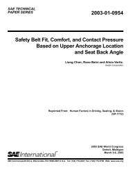
The flow chart of the new model-based TCS brake<br />
pressure estimation algorithm is shown in Figure 2. In this<br />
algorithm, the apply valve flow rate and the release valve<br />
flow rate are calculated separately. <strong>Based</strong> on the flow<br />
continuity equation, the TCS brake pressure estimation<br />
value is calculated. In order to simplify the algorithm for<br />
production implementation, the higher order dynamics of<br />
the algorithm are ignored; this is also found to be a valid<br />
assumption based on model analysis and model validation<br />
results.<br />
N<br />
A<br />
TCS Active<br />
Control model =<br />
Apply mode<br />
Control mode =<br />
Release mode<br />
Flow Rate = 0.0<br />
<strong>Brake</strong> <strong>Pressure</strong> = 0.0<br />
A<br />
Y<br />
N<br />
N<br />
Y<br />
Y<br />
VALIDATION OF THE BRAKE PRESSURE<br />
ESTIMATION ALGORITHM<br />
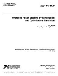
In order to evaluate the brake pressure estimation<br />
algorithm presented in this paper, the algorithm is<br />
programmed using MATLAB/SIMULINK. Vehicle data is<br />
used as inputs to the simulation model. The SIMULINK<br />
diagram is shown in Figure 3.<br />
The algorithm is validated for four pressure profiles:<br />
(i) Changes in pressure;<br />
(ii) High pressure;<br />
(iii) Modulated pressure;<br />
(iv) One channel activation;<br />
The simulation results for these four cases are shown in<br />
Figures 4 – 7.<br />
Figure 4 shows the simulation and the vehicle test results<br />
when the pressure increases and decreases quickly.<br />
Figure 5 shows the simulation and the vehicle test results<br />
when the pressure increases to a large amount of<br />
pressure on one wheel and a smaller pressure on the<br />
other wheel.<br />
Figure 6 shows the simulation and the vehicle test results<br />
when the pressure is applied and released several times.<br />
Figure 7 shows the simulation and the vehicle test results<br />
while only one channel is applying pressure.<br />
Calculate Flow Rate<br />
Calculate Flow Rate<br />
Figure 2 Flow chart of TCS brake pressure estimation algorithm<br />
Calculate <strong>Brake</strong> <strong>Pressure</strong>
TCS <strong>Brake</strong> <strong>Pressure</strong> Estimate <strong>Model</strong><br />
1<br />
s<br />
Xp<br />
Displacement<br />
Vs. <strong>Pressure</strong><br />
Ps<br />
Pc<br />
Apply Command<br />
Apply<br />
Valve<br />
Release Command Release<br />
Valve<br />
Figure 3 SIMULINK diagram of one channel brake pressure estimation model for TCS<br />
From the results, it is apparent that the new model-based<br />
TCS brake pressure estimation gives fairly accurate brake<br />
pressure estimation. Since this algorithm is based on a<br />
physical model, it can predict brake pressure accurately<br />
over all testing conditions. And a big advantage of the<br />
proposed algorithm is the reduction of calibration time.<br />
CONCLUSION<br />
In this paper, a model-based brake pressure estimation<br />
algorithm for TCS is presented. The algorithm is simplified<br />
based on model analysis to enable production<br />
implementation. The pressure estimation algorithm is<br />
validated using vehicle data. The simulation results show<br />
that the new algorithm can predict brake pressure<br />
accurately for traction control systems, and is robust for<br />
all testing cases.<br />
In addition, there are fewer calibration variables that need<br />
to be determined from testing than in the current<br />
algorithm. This means significant savings in calibration<br />
time and cost. This algorithm more accurately estimates<br />
the pressure at the driven wheel allowing the brake control<br />
systems to depend more heavily on this estimation. The<br />
improved algorithm can reduce brake wear and improve<br />
driver comfort during an active brake control event.<br />
ACKNOWLEDGMENTS<br />
The authors acknowledge gratefully the technical support<br />
of Bryan T. Fulmer, Joseph A. Elliott of <strong>Delphi</strong> Technical<br />
Q1<br />
Q2<br />
1/ap<br />
Xp_dot<br />
Center Brighton and James R. Bond of <strong>Delphi</strong> Technical<br />
Center Dayton. Specially, for the discussion with Bryan T.<br />
Fulmer<br />
REFERENCES<br />
1. Paul, J., Klinkner, W., Muller, A., “Electronic stability<br />
program - the new active safety system of mercedesbenz”<br />
SAE 97-06 957128.<br />
2. “Automotive <strong>Brake</strong> Systems,” Robert Bosch GmbH,<br />
1995.<br />
3. Merritt, H.E., “Hydraulic Control Systems” John Wiley<br />
and Sons, Inc., 1967.<br />
4. Doebelin, E.O., “System Dynamics <strong>Model</strong>ing,<br />
Analysis, Simulation, Design” Marcel Dekker, Inc.,<br />
1998.<br />
CONTACT<br />
Qingyuan Li and Keith W. Beyer are systems engineers<br />
in Chassis Systems, and Quan Zheng is a Controls<br />
engineer in Forward Energy and Energy Management<br />
Systems at <strong>Delphi</strong> Automotive Systems, Technical Center<br />
Brighton, 125<strong>01</strong> E. Grand River, Brighton, MI 48116. Their<br />
contacting emails are as follows:<br />
qingyuan.li@delphiauto.com.<br />
keith.w.beyer@delphiauto.com.<br />
quan.zheng@delphiauto.com
<strong>Pressure</strong>(PSI)<br />
<strong>Pressure</strong>(PSI)<br />
<strong>Pressure</strong>(PSI)<br />
<strong>Pressure</strong>(PSI)<br />
150<br />
100<br />
50<br />
0<br />
-50<br />
-100<br />
<strong>Model</strong> Estimated <strong>Pressure</strong> LR<br />
Measured <strong>Pressure</strong> LR<br />
-150<br />
0 1 2 3 4<br />
Time(Second)<br />
5 6 7 8 9<br />
300<br />
250<br />
200<br />
150<br />
100<br />
50<br />
0<br />
<strong>Model</strong> Estimated <strong>Pressure</strong> RR<br />
Measured <strong>Pressure</strong> RR<br />
-50<br />
0 1 2 3 4<br />
Time(Second)<br />
5 6 7 8 9<br />
Figure 4 Comparison of brake pressure estimation for quick changes in pressure<br />
200<br />
150<br />
100<br />
50<br />
0<br />
-50<br />
-100<br />
<strong>Model</strong> Estimated <strong>Pressure</strong> LR<br />
Measured <strong>Pressure</strong> LR<br />
-150<br />
0 1 2 3 4 5<br />
Time(Second)<br />
6 7 8 9 10<br />
350<br />
300<br />
250<br />
200<br />
150<br />
100<br />
50<br />
0<br />
<strong>Model</strong> Estimated <strong>Pressure</strong> RR<br />
Measured <strong>Pressure</strong> RR<br />
-50<br />
0 1 2 3 4 5<br />
Time(Second)<br />
6 7 8 9 10<br />
Figure 5 Comparison of brake pressure estimation for high pressure events
<strong>Pressure</strong>(PSI)<br />
<strong>Pressure</strong>(PSI)<br />
<strong>Pressure</strong>(PSI)<br />
150<br />
100<br />
50<br />
0<br />
-50<br />
-100<br />
<strong>Model</strong> Estimated <strong>Pressure</strong> LR<br />
Measured <strong>Pressure</strong> LR<br />
-150<br />
0 1 2 3 4 5<br />
Time(Second)<br />
6 7 8 9 10<br />
120<br />
100<br />
80<br />
60<br />
40<br />
20<br />
0<br />
<strong>Model</strong> Estimated <strong>Pressure</strong> RR<br />
Measured <strong>Pressure</strong> RR<br />
-20<br />
0 1 2 3 4 5<br />
Time(Second)<br />
6 7 8 9 10<br />
Figure 6 Comparison of brake pressure estimation during pressure modulation<br />
<strong>Pressure</strong>(PSI)<br />
200<br />
150<br />
100<br />
50<br />
0<br />
-50<br />
-100<br />
<strong>Model</strong> Estimated <strong>Pressure</strong> LR<br />
Measured <strong>Pressure</strong> LR<br />
-150<br />
0 1 2 3 4<br />
Time(Second)<br />
5 6 7 8<br />
300<br />
250<br />
200<br />
150<br />
100<br />
50<br />
0<br />
<strong>Model</strong> Estimated <strong>Pressure</strong> RR<br />
Measured <strong>Pressure</strong> RR<br />
-50<br />
0 1 2 3 4<br />
Time(Second)<br />
5 6 7 8<br />
Figure 7 Comparison of brake pressure estimation for pressure activation on one channel