Technology and Terminology of Knapped Stone - IRIT
Technology and Terminology of Knapped Stone - IRIT
Technology and Terminology of Knapped Stone - IRIT

You also want an ePaper? Increase the reach of your titles
YUMPU automatically turns print PDFs into web optimized ePapers that Google loves.
<strong>Technology</strong><br />
<strong>and</strong><br />
<strong>Terminology</strong><br />
<strong>of</strong><br />
<strong>Knapped</strong> Ston e<br />
M.-L. Iniza n<br />
M. Reduron-Ballinge r<br />
H. Roch e<br />
J. Tixie r<br />
Translated b y<br />
J, Feblot-Augustin s<br />
CREP
<strong>Technology</strong><br />
<strong>and</strong> Terminolog y<br />
<strong>of</strong> <strong>Knapped</strong> Ston e
In the same collection<br />
Préhistoire d e la Pierre Taillé e<br />
Published by Cercle de Recherches et d'Etudes Préhistorique s<br />
Maison de l'Archéologie et de l'Ethnologie (Boît e 3)<br />
21, allée de l'Université - 92023 Nanterre Cede x - France<br />
Tome 5<br />
Tome 1 - Terminologie et Technologie (out <strong>of</strong> print)<br />
Tome 2 - Economie du débitage laminaire<br />
Tome 3 - <strong>Technology</strong> <strong>of</strong> <strong>Knapped</strong> <strong>Stone</strong> (out <strong>of</strong> print)<br />
Tome 4 - Technologie de la Pierre Taillée<br />
<strong>Technology</strong> <strong>and</strong> <strong>Terminology</strong> <strong>of</strong> <strong>Knapped</strong> <strong>Stone</strong> followed by a multilingual<br />
vocabulary (Arabic, English, French, German, Greek, Italian, Portuguese,<br />
Spanish) / Marie-Louise Inizan, Michèle Reduron-Ballinger, Hélène Roche,<br />
Jacques Tixier, translated by Jehanne Féblot-Augustins. Nanterre : C.R.E.P.,<br />
1999 - 191 pages : 80 ill.; (Préhistoire de la Pierre Taillée; 5).<br />
ISBN 2-903516-05-7<br />
ISBN 2-903516-05-7<br />
© CREP 1999<br />
Cover : © J. Tixier
Préhistoire d e la Pierre Taillé e<br />
Tome 5<br />
<strong>Technology</strong><br />
<strong>and</strong> Terminolog y<br />
<strong>of</strong> <strong>Knapped</strong> Ston e<br />
Followed b y a multilingual vocabular y<br />
Arabic, English, French, German, Greek , Italian , Portuguese, Spanis h<br />
Marie-Louise Iniza n<br />
Michèle Reduron-Ballinge r<br />
Hélène Roch e<br />
Jacques Tixie r<br />
Translated b y Jehanne Féblot-Augustin s<br />
Nanterre : CREP<br />
1999
Authors<br />
Marie-Louise Inizan*, Michèle Reduron-Ballinger**, Hélène Roche*, Jacques Tixier*<br />
Translation<br />
Jehanne Féblot-Augustins*<br />
*UMR Préhistoire et Technologie - CNRS<br />
**UMS 844 - CNRS<br />
Maison de l'Archéologie et de l'Ethnologie (Boîte 3)<br />
21, allée de l'Université<br />
92023 Nanterre Cedex, France<br />
roche @mae.u-paris10.fr<br />
Acknowledgments<br />
We thank O. Bar Yosef, L. Bourguignon, J.-P. Brugal, M. Charleux, M. Dauvois, J. Jaubert,<br />
J.-G. Marcillaud, L. Meignen, A, Morala, A.-M. <strong>and</strong> P. Pétrequin, P.-J. Texier B. V<strong>and</strong>ermeersch,<br />
for allowing the reproduction <strong>of</strong> documents, sometimes unpublished.<br />
We also thank I. Johnson for translating the first half <strong>of</strong> chapter 7 <strong>and</strong> B. Lequeux for her help<br />
during the preparation <strong>of</strong> this book.
Contents<br />
List <strong>of</strong> illustrations 8<br />
Foreword 11<br />
Introduction : <strong>Technology</strong> 13<br />
Chapter 1 : Raw materials 19<br />
<strong>Knapped</strong> hard rocks 19<br />
1. Mineralogy 19<br />
2. Knapping suitability <strong>of</strong> hard rocks 21<br />
2.1. An experimenter's viewpoint 21<br />
2.2. Heat treatment <strong>of</strong> raw materials 23<br />
Raw material procurement strategies 25<br />
1. Provenance <strong>of</strong> raw material 26<br />
2. Local availability <strong>of</strong> raw material 26<br />
3. Transport to the campsite 26<br />
Chapter 2 : Knapping 29<br />
Intentional knapping 29<br />
Knapping : shaping, flaking, retouching 30<br />
Knapping methods <strong>and</strong> techniques 30<br />
The main techniques 30<br />
1. Percussion 30<br />
2. Pressure 32<br />
Knapping products 32<br />
1. Describing a flake 33<br />
2. Characteristic flakes 34<br />
3. Knapping waste products 34<br />
4. Knapping accidents 34<br />
4.1. Breaks 34<br />
4.2. Plunging flakes 36<br />
4.3. Hinged flakes 36<br />
4.4. Miscellaneous 36<br />
Chapter 3 : Shaping 43<br />
Bifacial shaping 44<br />
1. Methods 44<br />
2. Techniques 44<br />
3. Morphologies 45<br />
Polyhedral <strong>and</strong> spheroidal shaping 49<br />
Other shaping methods 51<br />
Preforms 51<br />
The cleaver : a very specific tool 55<br />
5
Chapter 4 : Debitage 59<br />
The core<br />
Debitage products 60<br />
Debitage methods 60<br />
1. Simple debitage 61<br />
2. Predetermined debitage ••• 61<br />
2.1. The Levallois methods 61<br />
2.2. The Kombewa method 68<br />
2.3. Blade debitage 71<br />
Percussion debitage <strong>of</strong> blades 73<br />
Pressure debitage <strong>of</strong> blades 76<br />
Chapter 5 : Retouching 81<br />
Definition 81<br />
Characteristics • 81<br />
Orientation <strong>of</strong> tools 82<br />
Special techniques <strong>and</strong> their products 82<br />
1. Microburin blow technique 82<br />
2. Burin blow technique 84<br />
3. Tranchet blow technique 85<br />
4. Clactonian notch technique 85<br />
5. Other techniques 85<br />
Chapter 6 : <strong>Technology</strong> a s a means to an end 89<br />
Reading a stone object..... 89<br />
1. Observation <strong>of</strong> surface conditions 91<br />
2. Type <strong>of</strong> surface conditions 91<br />
2.1. Natural alterations 91<br />
2.2. Mechanical devices 92<br />
2.3. Humanly induced alterations 92<br />
2.4. Additions 93<br />
3. Framework for the reading <strong>of</strong> a knapped stone object 93<br />
3.1. Observation <strong>of</strong> surface conditions 93<br />
3.2. Characterization <strong>of</strong> the raw material 93<br />
3.3. Identification <strong>of</strong> the blank, if recognizable 93<br />
3.4. Special knapping techniques 93<br />
3.5. Description <strong>of</strong> removals by means <strong>of</strong> their main characteristics 94<br />
3.6. Defining the object whether it be a tool or not 94<br />
Underst<strong>and</strong>ing a lithic assemblage 94<br />
1. Conjoins <strong>and</strong> refits..... 94<br />
2. Knapping experiments 96<br />
3. Traces <strong>of</strong> use 98<br />
4. Technical behaviour 99<br />
4.1. Assessment 99<br />
4.2. Interpretation 10<br />
Chapter 7 : Graphic representation 101<br />
Planning 101<br />
1. What to draw 101<br />
2. How to draw 102<br />
6<br />
5 9
Drawing 102<br />
1. General principles 102<br />
2. Layout conventions 105<br />
3. Description <strong>of</strong> the object 108<br />
3.1. Views 108<br />
3.2. Sections <strong>and</strong> section views 110<br />
4. Graphic design <strong>and</strong> technique 1ll<br />
4.1. Drafting Ill<br />
4.2. Pencil drawing 1ll<br />
4.3. Pen <strong>and</strong> ink drawing 114<br />
5. Materials <strong>and</strong> surfaces 114<br />
5.1. Raw materials 114<br />
5.2. Natural surfaces 116<br />
5.3. Alterations 120<br />
5.4. Additions 120<br />
6. Symbols 121<br />
Assessing 123<br />
1. Scale 123<br />
2. Orientation 124<br />
3. Descriptive views 124<br />
4. Removals 125<br />
5. Symbols 125<br />
6. Style <strong>of</strong> drawings 125<br />
Schematizing 125<br />
1. Schematic representation <strong>of</strong> an object 125<br />
2. Schematic representation <strong>of</strong> a chaîne opératoire 126<br />
Chapter 8 : Terminological Lexico n 129<br />
Bibliography 159<br />
Multilingual Vocabular y 169<br />
English/Arabic — Arabic/English 171<br />
English/French — French/English 174<br />
English/German — German/English 177<br />
English/Greek — Greek/English 180<br />
English/Italian — Italian/English 183<br />
English/Portuguese — Portuguese/English 186<br />
English/Spanish — Spanish/English 189<br />
7
List o f illustration s<br />
Fig. 1 Raw materials<br />
Fig. 2 Knapping suitability tests<br />
Fig. 3 Raw material procurement strategies<br />
Fig. 4 Knapping techniques<br />
Fig. 5 Main descriptive terms for flakes<br />
Fig. 6 Large blade with multiple breaks<br />
Fig. 7 Experimental knapping accidents<br />
Fig. 8 Bifacial shaping <strong>of</strong> an arrowhead<br />
Fig. 9 Blade debitage carried out on a core with a single striking platform<br />
Fig. 10 Blade debitage carried out on a core with two opposite striking platforms<br />
Fig. 11 Bifacial <strong>and</strong> bilateral equilibrium planes <strong>of</strong> an h<strong>and</strong>axe<br />
Fig. 12 Various examples <strong>of</strong> bifacial shaping<br />
Fig. 13 Example <strong>of</strong> bifacial shaping<br />
Fig. 14 Bifacial-shaping flakes<br />
Fig. 15 Point <strong>of</strong> balance or point <strong>of</strong> gravity (point G) in polyhedral <strong>and</strong> spheroidal shapin:<br />
Fig. 16 Polyhedral <strong>and</strong> spheroidal shaping<br />
Fig. 17 Trihedral shaping<br />
Fig. 18 Preforms<br />
Fig. 19 Phonolite cleaver<br />
Fig. 20 Main descriptive terms for cores<br />
Fig. 21 Relatively simple debitage<br />
Fig. 22 Volumetric representation <strong>of</strong> two Levallois debitage methods<br />
Fig. 23 Levallois debitage <strong>of</strong> a preferential flake<br />
Fig. 24 Recurrent centripetal Levallois debitage<br />
Fig. 25 Debitage <strong>of</strong> a Levallois point<br />
Fig. 26 Various examples <strong>of</strong> Levallois products<br />
Fig. 27 Debitage <strong>of</strong> a Kombewa flake<br />
Fig. 28 Phonolite cleaver on a Kombewa flake<br />
Fig. 29 Various types <strong>of</strong> blade-cores produced by percussion<br />
Fig. 30 Experimental blade <strong>and</strong> bladelet debitage positions<br />
Fig. 31 Pressure debitage <strong>of</strong> blades (or bladelets), different types <strong>of</strong> cores<br />
Fig. 32 The Yubetsu method<br />
Fig. 33 Microburin blow technique<br />
Fig. 34 Various examples <strong>of</strong> special techniques<br />
Fig. 35 Thermal damage<br />
Fig. 36 Refitting<br />
Fig. 37 Acheulean h<strong>and</strong>axe<br />
Fig. 38 Various examples <strong>of</strong> debitage products<br />
Fig. 39 Pressure-flaked bladelet-core, subsequently percussion-flaked<br />
Fig. 40 Refitting<br />
Fig. 41 Examples <strong>of</strong> orientation<br />
Fig. 42 Views used in lithic illustration (French system)<br />
Fig. 43 Two layouts <strong>of</strong> views. 1: French system. 2 : American system<br />
Fig. 44 Different ways <strong>of</strong> describing the volume <strong>of</strong> an object<br />
Fig. 45 The stages involved in the drawing process<br />
Fig. 46 Tracing the outline <strong>and</strong> the arrises<br />
Fig. 47 Uncompleted laurel leaf<br />
Fig. 48 Graphical treatment <strong>of</strong> various raw materials<br />
Fig. 49 Graphical rendering <strong>of</strong> the texture <strong>of</strong> various materials<br />
Fig. 50 Large convex Mousterian sidescraper on a frost-fractured flake<br />
8
Fig. 51 Proximal fragment <strong>of</strong> a Canaanean blade bearing traces <strong>of</strong> gloss <strong>and</strong> bitumen<br />
Fig. 52 Symbolic conventions in figurative drawings<br />
Fig. 53 Illustration <strong>of</strong> the main symbols used<br />
Fig. 54 Schematic representation <strong>of</strong> an object<br />
Fig. 55 Schematic representation <strong>of</strong> a chaîne opératoire<br />
Fig. 56 Angle <strong>of</strong> removals<br />
Fig. 57 Various examples <strong>of</strong> simple burins<br />
Fig. 58 Surfaces liable to be used as striking or pressure platforms for burin blows<br />
Fig. 59 Various examples <strong>of</strong> multiple burins<br />
Fig. 60 Inclination <strong>of</strong> a burin facet to the lower face <strong>of</strong> a blade<br />
Fig. 61 Schematic illustration <strong>of</strong> the main types <strong>of</strong> burin spalls<br />
Fig. 62 Various types <strong>of</strong> butts<br />
Fig. 63 Fluting experiment<br />
Fig. 64 Schematic illustration <strong>of</strong> blade debitage on a crested core<br />
Fig. 65 Delineation <strong>of</strong> the edge created by a series <strong>of</strong> removals<br />
Fig. 66 Distribution <strong>of</strong> removals along an edge<br />
Fig. 67 Extent <strong>of</strong> removals<br />
Fig. 68 Thermally treated <strong>and</strong> subsequently pressure-retouched flint blade<br />
Fig. 69 Localization <strong>of</strong> removals, various examples<br />
Fig. 70 Morphology <strong>of</strong> removals<br />
Fig. 71 Examples <strong>of</strong> oblique covering parallel retouch<br />
Fig. 72 The stone-knapper's set <strong>of</strong> tools for percussion<br />
Fig. 73 The stone-knapper's set <strong>of</strong> tools for pressure<br />
Fig. 74 Various examples <strong>of</strong> plunging blades <strong>and</strong> flakes<br />
Fig. 75 Position <strong>of</strong> removals<br />
Fig. 76 Examples <strong>of</strong> preparation<br />
Fig. 77 Core tablet <strong>and</strong> rejuvenation flake<br />
Fig. 78 Proximal fragments <strong>of</strong> pressure-flaked obsidian bladelets, showing traces <strong>of</strong> rubbing<br />
down on their upper faces<br />
Fig. 79 Various examples <strong>of</strong> sharpening on simple burins<br />
Fig. 80 "Siret" accidental break<br />
9
Foreword<br />
Many students <strong>and</strong> researchers have felt the need for an up-to-date guide to the jungle <strong>of</strong><br />
prehistoric worked stone, either for pr<strong>of</strong>essional purposes or from personal curiosity.<br />
The qualities <strong>of</strong> worked stone, in addition to its imperishable nature <strong>and</strong> its use since the<br />
dawn <strong>of</strong> prehistoric time, certainly confer a special status on it until its replacement by more<br />
versatile materials such as metals. Nevertheless, it would be a mistake to think that stone-working<br />
contributes to the underst<strong>and</strong>ing <strong>of</strong> past behaviour for prehistoric societies alone. The abundance<br />
<strong>of</strong> easily available raw materials as well as the existence <strong>of</strong> technical expertises allowed the use<br />
<strong>of</strong> worked stone to continue into historical time. The true decline in the use <strong>of</strong> worked stone<br />
seems to coincide with the appearance <strong>of</strong> iron. However, let us not overlook gun flints <strong>and</strong><br />
tinderboxes, nor the threshing sledge (tribulum), still in use today in agriculture.<br />
The first French edition <strong>of</strong> Préhistoire de la pierre taillée in 1980 1<br />
contributed to a<br />
renewal in the interpretation <strong>of</strong> lithic assemblages from a technical viewpoint. It included the<br />
terminological lexicon published by one <strong>of</strong> the authors in 1963 2<br />
, <strong>and</strong> translated by M. Newcomer<br />
in 1974 3<br />
, which was relatively rudimentary <strong>and</strong> still oriented more towards typology than<br />
technology.<br />
In 1992, a new edition, in English 4<br />
, gave us the opportunity to take into account recent<br />
advances in underst<strong>and</strong>ing the technology <strong>of</strong> knapped stone, as much from a theoretical<br />
st<strong>and</strong>point as in archaeological applications. Like the earlier editions, it was intended as a basic<br />
reference book for as wide a public as possible. A multiligual lexicon in eight languages was<br />
appended, written by prehistorians in their own mother-tongues, which should ease communication<br />
<strong>and</strong> subsequently enrich the field <strong>of</strong> technology.<br />
The new 1995 French edition 5<br />
, <strong>of</strong> which this latest English edition is the unabridged<br />
translation, was entirely revised; amongst other additions, a chapter devoted to graphic<br />
expression was included, being essential to communication in technological studies. The<br />
multilingual lexicon (with Portuguese added) 6<br />
is <strong>of</strong> course appended to the present edition.<br />
1 Tixier, Inizan, Roche, 1980.<br />
2 Tixier, 1963.<br />
3 Tixier, 1974.<br />
4 Inizan, Roche, Tixier, 1992.<br />
5 Inizan, Reduron, Roche, Tixier, 1995.<br />
6 Fellow prehistorians kindly took on this task : Joachim Hahn (Tubingen University) wrote the German text, Sulta n<br />
Muhesen (Director <strong>of</strong> Antiquities <strong>and</strong> Museums <strong>of</strong> Syria) the Arabic text, Sergio Ripoll (Madrid, National University<br />
"a Distancia") the Spanish, Antiklia Moundrea the Greek, Daniell a Zampett i (Rome, University "La Sapienza") the<br />
Italian, <strong>and</strong> Lui s Rapos o (Lisbon, National Museum <strong>of</strong> Archaeology) the Portuguese.<br />
11
Introduction<br />
<strong>Technology</strong><br />
The term technology is here reserved for a conceptual approach to prehistoric material<br />
culture, based on the reasoned study <strong>of</strong> techniques, including those <strong>of</strong> human physical actions. It<br />
is appropriate to recall that we are indebted to M. Mauss 7<br />
for this notion <strong>of</strong> technique per se,<br />
divorced from material objects, ins<strong>of</strong>ar as he considered bodily actions, such as dancing for<br />
instance, as techniques. Arguing along similar lines, A.-G. Haudricourt 8<br />
writes : "While the same<br />
object can be studied from different viewpoints, that which consists in defining the laws <strong>of</strong><br />
creation <strong>and</strong> <strong>of</strong> transformation <strong>of</strong> an object is undeniably the most essential <strong>of</strong> all viewpoints. It<br />
is clear that the essential aspect <strong>of</strong> a manufactured object resides in the fact that it is made <strong>and</strong><br />
used by man; it is also clear that if technology is to be a science, it must be the science <strong>of</strong> human<br />
activities".<br />
Although the present essay is concerned solely with the technology <strong>of</strong> knapped stone,<br />
one should nevertheless bear in mind that technology encompasses the entire technical system at<br />
play in a culture. The study <strong>of</strong> knapped stone was very soon given prominence to in prehistory<br />
because lithics <strong>of</strong>fer the earliest evidence <strong>of</strong> a well preserved technique. However, other studies<br />
soon followed, devoted amongst others to organic material culture, <strong>and</strong> to later achievements<br />
involving the use <strong>of</strong> fire, such as ceramics, metal, glass, etc.<br />
The study <strong>of</strong> techniques does not lead to technology alone. Indeed, when establishing<br />
chronologies, archaeologists have always been concerned about the invention <strong>of</strong> techniques, their<br />
complexity, <strong>and</strong> their ability to identify a culture. Likewise, no typology can be fully operative<br />
if it does not take techniques into at least partial account. We do not therefore consider<br />
substituting technology for typology, for they represent two distinct approaches developed to<br />
meet different ends; they can however be used concurrently, <strong>and</strong> great benefit can be derived<br />
from the comparison <strong>of</strong> the results they yield.<br />
Technological analysis must, in each <strong>and</strong> every circumstance, enable one to assess what<br />
pertains to deterministic constraints, before cultural choices are assumed.<br />
7 Mauss, 1947.<br />
8 "Si l'on peut étudier le même objet de différents points de vue, il est par contre sûr qu'il y a un point de vue plus<br />
essentiel que les autres, celui qui peut donner les lois d'apparition et de transformation de l'objet. Il est clair que pour<br />
un objet fabriqué c'est le point de vue humain de sa fabrication et de son utilisation par les hommes qui est essentiel,<br />
et que si la technologie doit être une science, c'est en tant que science des activités humaines'". Haudricourt, 1964 :<br />
28.<br />
13
Why?<br />
<strong>Technology</strong> has its place within an original stream <strong>of</strong> French anthropological research,<br />
thanks to the pioneering work <strong>of</strong> A. Leroi-Gourhan. It has since then become an independant field<br />
<strong>of</strong> research in prehistory. A. Leroi-Gourhan 9<br />
, who was by calling an ethnologist <strong>and</strong> subsequently<br />
a prehistorian, published in 1943 L'homme et la matière, the first volume <strong>of</strong> Evolution<br />
et techniques, a book that the successive generations <strong>of</strong> researchers discover anew with unabated<br />
interest. His entire work was dedicated to the quest for mankind through the study <strong>of</strong> technical,<br />
social or symbolic patterns <strong>of</strong> behaviour 10<br />
. He held the Chair <strong>of</strong> Prehistoric Ethnology, created<br />
for him at the Collège de France, <strong>and</strong> over a period <strong>of</strong> many years the rigour <strong>of</strong> his teaching,<br />
within the framework <strong>of</strong> that institution as well as at the prehistoric site <strong>of</strong> Pincevent - a genuine<br />
research laboratory from 1964 onwards - has significantly widened the scope <strong>of</strong> scientific<br />
research in prehistory 11<br />
.<br />
12<br />
One <strong>of</strong> Leroi-Gourhan's original contributions was the concept <strong>of</strong> chaîne opératoire ,<br />
which forms the basis <strong>of</strong> the approach to technology developed in this book. In the study <strong>of</strong> a<br />
lithic assemblage, the chaîne opératoire encompasses all the successive processes, from the<br />
procurement <strong>of</strong> raw material until it is discarded, passing through all the stages <strong>of</strong> manufacture<br />
<strong>and</strong> use <strong>of</strong> the different components. The concept <strong>of</strong> chaîne opératoire makes it possible to<br />
structure man's use <strong>of</strong> materials by placing each artefact in a technical context, <strong>and</strong> <strong>of</strong>fers a<br />
methodological framework for each level <strong>of</strong> interpretation. An identical trend in French<br />
ethnology contributed to the emergence <strong>of</strong> a "school <strong>of</strong> cultural technology" 13<br />
, which publishes<br />
the periodical Techniques et culture. This group helped both to rehabilitate the study <strong>of</strong> material<br />
culture, by demonstrating that any technical fact is a social or a cultural fact, <strong>and</strong> to widen the<br />
field <strong>of</strong> study <strong>of</strong> the technical system by showing the need to take into account all possible<br />
technical variants.<br />
How?<br />
A methodolog y<br />
The procedures we have developed in our technological approach are applied solely to<br />
the analysis <strong>of</strong> knapped stone assemblages, <strong>and</strong> this is quite deliberate : the novel questions<br />
investigated by prehistorians-technologists have given rise to new lines <strong>of</strong> research that require<br />
operative methodological tools.<br />
• The notion <strong>of</strong> technical system 14<br />
: by treating stone-knapping as a sub-system 15<br />
, one<br />
can readily see what insight can be gained into the history <strong>of</strong> a prehistoric group through the<br />
study <strong>of</strong> its techniques. Analysing the interdependance <strong>of</strong> different sub-systems brings a new<br />
level <strong>of</strong> inferences within reach : lithics endowed with such properties as cutting, boring, rasping,<br />
scraping, etc., fulfill a number <strong>of</strong> needs that are necessarily linked to specific activities, which<br />
9 Leroi-Gourhan, 1943 <strong>and</strong> 1964.<br />
10 "Sur le long chemin que doivent encore parcourir les sciences humaines avant qu'elles deviennent réellement la<br />
philosophie et, donc, avant de pouvoir nourrir réellement la philosophie, André Leroi-Gourhan est certainement un<br />
géant" ("On the long road that the human sciences have yet to cover before really becoming philosophy, <strong>and</strong> therefore<br />
before being really able to nurture philosophy, André Leroi-Gourhan is certainly a giant"). Cresswell, 1989 : 26.<br />
11 M. Julien (1992) wrote an essay that examines the present state <strong>of</strong> the subject.<br />
12 The term "chaîne opératoire" is considered from a technological st<strong>and</strong>point; without attempting a definition <strong>of</strong> the<br />
concept, we shall try to show in what way it is operative. This French expression seems to be increasingly used by<br />
English-speaking technologists, as shown by volume 9 : 1 <strong>of</strong> the Cambridge Archaeological Review, which deals with<br />
<strong>Technology</strong> in the Humanities. It will therefore be left untranslated throughout the text.<br />
13 Around R. Cresswell.<br />
14 "L'ensemble des techniques forme des industries et des métiers. L'ensemble : techniques, industries et métiers,<br />
forme le système technique d'une société " ("Techniques as a whole generate industries <strong>and</strong> crafts. The set : techniques,<br />
industries <strong>and</strong> crafts, corresponds to the technical system <strong>of</strong> a society"). Mauss, 1947 : 29.<br />
15 Perlès, 1987 : 22.<br />
14
ing other sub-systems into play. It is by cross-examining the results <strong>of</strong> different analyses<br />
pertaining to the activities common actions involve, that we give greater substance to our<br />
interpretations ; however, we are only just beginning to use the notion <strong>of</strong> technical system<br />
efficiently as a means <strong>of</strong> approaching the study <strong>of</strong> behaviour.<br />
In such a perspective, knapped stone industries can be studied through a combination <strong>of</strong><br />
identifiable elements such as tools, raw materials, physical actions <strong>and</strong> skills.<br />
Tools (the term is used here in its broader sense <strong>and</strong> refers to the object <strong>of</strong> knapping<br />
operations) are given prominence to in typological studies ; they are however narrowly dependant<br />
on raw materials, human physical actions <strong>and</strong> skills.<br />
Raw materials belong to a geological context. Their knapping is ruled by specific laws<br />
pertaining to fracture mechanics, which vary according to the type <strong>of</strong> stone. Raw materials can<br />
be worked directly, or they can be structurally modified beforeh<strong>and</strong>, notably by heat treatment.<br />
Physical actions are linked to psychomotor functions : the h<strong>and</strong> <strong>and</strong> the body act<br />
according to orders transmitted by the brain, within the limits <strong>of</strong> human motor abilities.<br />
Skills are the result <strong>of</strong> motor dexterities <strong>and</strong> cognitive capacities that operate in<br />
combination with knowledge ; they can be assessed in terms <strong>of</strong> competences <strong>and</strong> performances 16<br />
(see p. 100). The transmission <strong>of</strong> skills involves a learning process, which can only take place<br />
between individuals within the social group ; this collective knowledge can also be communicated<br />
to other groups. The analysis <strong>of</strong> skills is an essential prerequisite for the appraisement <strong>of</strong><br />
technical facts in a given culture (ch. 6).<br />
• Another notion concerns projects <strong>and</strong> the means by which they are implemented.<br />
Knapping activities are subtended by more or less elaborate projects, which can be apprehended<br />
through the reconstitution <strong>of</strong> the associated chaînes opératoires. In knapping operations, the<br />
project includes a conceptua l scheme , <strong>of</strong> an intellectual nature, which is itself implemented<br />
through a series <strong>of</strong> operations termed operativ e knappin g scheme(s) . Within a single chaîne<br />
opératoire, the relationships between conceptual <strong>and</strong> operative schemes, knowledge <strong>and</strong> skills,<br />
techniques <strong>and</strong> methods, are organized in the following way :<br />
knowledge<br />
skills<br />
dexterity<br />
(ch. 6)<br />
16 Pelegrin, 1995.<br />
PROJECT<br />
CONCEPTUAL SCHEME<br />
OPERATIVE SCHEME<br />
raw material procurement (ch. 1)<br />
shaping (ch. 3)<br />
debitage (ch. 4)<br />
retouching (ch. 5)<br />
use <strong>and</strong> fonction<br />
discard<br />
methods<br />
<strong>and</strong><br />
techniques<br />
(ch. 2)<br />
15
In blade debitage 17<br />
, for instance, the project <strong>of</strong> the prehistoric knapper is easy to<br />
identify : his intent is to achieve elongated blanks <strong>of</strong> varied morphology. However, depending on<br />
the culture he belongs to, the knapper will use specific conceptual <strong>and</strong> operative schemes in order<br />
to carry out his project. To be able to demonstrate the existence <strong>of</strong> such schemes, one must<br />
register in detail all the pieces <strong>of</strong> information <strong>and</strong> show forth "regularities" 18<br />
, first within one<br />
lithic assemblage <strong>and</strong> subsequently within others that are comparable. Indeed, without the<br />
repeated observation <strong>of</strong> phenomena, <strong>of</strong> similar facts, archaeologists have no basis for comparison<br />
<strong>and</strong> are limited to anecdotal evidence.<br />
• <strong>Technology</strong> is also dedicated to the study <strong>of</strong> relationships between the technical system<br />
<strong>and</strong> socio-economic phenomena. This is one <strong>of</strong> the most fruitful <strong>and</strong> rapidly developing means<br />
<strong>of</strong> approaching prehistoric life-styles.<br />
<strong>Knapped</strong> stone industries can be studied in terms <strong>of</strong> economy. By economy, we refer to<br />
a differential management <strong>of</strong> raw materials, blanks, or tools. For instance, if on a site yielding<br />
several raw materials the various types <strong>of</strong> tools have been made indiscriminately from any <strong>of</strong> the<br />
said raw materials, we do not have a case <strong>of</strong> raw material economy. Conversely, if it can be<br />
shown that choices were made, the term economy becomes relevant, <strong>and</strong> applies, depending on<br />
the case, to raw materials, to debitage products or to tools. The quality <strong>and</strong> availability <strong>of</strong> raw<br />
material must however be assessed before any assumption concerning the nature <strong>of</strong> the choices<br />
is made : before ascribing the use <strong>of</strong> microliths to a cultural choice, it is advisable to make sure<br />
whether or no the available raw material could allow the manufacture <strong>of</strong> larger tools. Any lithic<br />
industry can therefore be studied, as a whole, in such techno-economic terms, provided one bears<br />
in mind that technical variants may result from a cultural choice.<br />
"Reading" stone object s<br />
Reading takes place on two levels.<br />
• The first level is that <strong>of</strong> observation, an initial reading <strong>of</strong> knapping scars. It involves<br />
the technical reading <strong>of</strong> each artefact (whether it be an ordinary flake or a waste product or the<br />
most elaborate tool) in order to assess its position in the chaîne opératoire, <strong>and</strong> is independant<br />
<strong>of</strong> the archaeological context. This chain, as we previously mentioned, encompasses not only the<br />
moment <strong>of</strong> manufacture <strong>of</strong> the artefact, but its subsequent use <strong>and</strong> discard, <strong>and</strong> in the first<br />
instance the procurement <strong>of</strong> raw material ; in fact, it includes the entire history <strong>of</strong> the artefact up<br />
to the moment <strong>of</strong> its analysis.<br />
• The second level is one <strong>of</strong> inference. This is a matter <strong>of</strong> interpreting the interdependance<br />
<strong>of</strong> artefacts in the chaîne opératoire, even if links are missing. Presence or absence are<br />
significant in the context <strong>of</strong> interpretation. For instance, the absence or the low frequency <strong>of</strong><br />
cortical flakes in a knapping workshop suggest that the raw materials were tested or roughed out<br />
elsewhere. Again, a blade workshop without blades is also conceivable; the presence <strong>of</strong><br />
characteristic products, such as cores <strong>and</strong> crested blades, is evidence enough <strong>of</strong> the activities <strong>and</strong><br />
<strong>of</strong> the knapping project carried out at the site. Connections must also be sought between this<br />
second level <strong>of</strong> inference <strong>and</strong> the other technical activities stone-working involves.<br />
The value <strong>of</strong> such inferences will be contingent not only upon the type <strong>of</strong> lithic remains<br />
brought to light, but also upon the recognition <strong>of</strong> techniques <strong>and</strong> methods, <strong>and</strong> consequently upon<br />
our own underst<strong>and</strong>ing <strong>of</strong> chaînes opératoires.<br />
On a site, there may be evidence for just one chaîne opératoire, but more <strong>of</strong>ten there are<br />
many, corresponding with the different strategies brought into play by prehistoric people in the<br />
course <strong>of</strong> their various activites, or in the context <strong>of</strong> postponed activities. Whatever the case, all<br />
the phases <strong>of</strong> a chaîne opératoire are not necessarily represented on a site or on the excavated<br />
portion <strong>of</strong> a site.<br />
17 In French, the term débitage ("debitage" in English) refers both to the action <strong>of</strong> flaking <strong>and</strong> to the tangible results<br />
(debitage products) <strong>of</strong> this action.<br />
18 Gallay, 1986 : 115.<br />
16
<strong>Terminology</strong><br />
The problem <strong>of</strong> a uniform descriptive vocabulary arises from the outset. Any reading <strong>of</strong><br />
archaeological material would be pointless if it were not followed by exchange <strong>and</strong> communication.<br />
Indeed, by acknowledging that words are tools 19<br />
, we realize how much a precise<br />
vocabulary can improve the effectiveness <strong>of</strong> our analyses. Homage must once again be paid to<br />
A. Leroi-Gourhan : during his seminars on habitation structures (lato sensu) at the Collège de<br />
France, he initiated a process <strong>of</strong> collective reflection leading to the establisment <strong>of</strong> "a provisional<br />
vocabulary, in which the major concern was to eschew the pitfall <strong>of</strong> words <strong>and</strong> <strong>of</strong> uncontrolled<br />
identification" 20<br />
. The terminological lexicon presented here deals with the vocabulary <strong>of</strong> lithic<br />
technology. Many <strong>of</strong> the terms are conventional, <strong>and</strong> deliberately taken from terminology in<br />
current use. Even if they are not quite apt, they have become established by usage <strong>and</strong> are<br />
therefore convenient : stripped <strong>of</strong> their original meaning, they are already integrated into a<br />
specialized vocabulary (for instance, terms such as burin, microburin, Levallois, etc.).<br />
The wish to untangle confusions, reduce synonymies <strong>and</strong> suppress ambiguities has<br />
guided our choices. We have avoided equivocal technical terms, <strong>and</strong> have tried to stick to a single<br />
term when describing the same phenomenon.<br />
Lithic illustratio n<br />
The same procedures have been applied to the illustration <strong>of</strong> lithics. Drawings should not<br />
be considered as a prop for words <strong>and</strong> definitions, but as a genuine informative technological<br />
writing, <strong>and</strong> this is what we have attempted (ch. 7). Far from being mere reproductions <strong>of</strong> stone<br />
artefacts, the drawings <strong>and</strong> diagrams presented here were conceived at the same time as the text<br />
<strong>and</strong> can even substitute for it, the symbols used being equivalent to a terminology. If a clear<br />
sentence is better than a vague generic term, an accurate technical drawing can usefully replace<br />
a vague description.<br />
19 "However, I think it is important that researchers recognize that their words are their tools, just as stone artifacts<br />
they study were the tools <strong>of</strong> people". Boksenbaum, 1977 : 30.<br />
20 "un vocabulaire d'attente, où dominait le parti d'échapper au piège des mots et de l'identification sans contrôle".<br />
Leroi-Gourhan, 1982 : 3.<br />
17
Chapter 1<br />
Raw material s<br />
<strong>Knapped</strong> har d rock s<br />
1. Mineralog y<br />
Prehistoric people worked a large variety <strong>of</strong> raw materials, rocks mainly but also quartz,<br />
which is a mineral.<br />
<strong>Knapped</strong> stones are connected with the geological context in which the earliest knappers<br />
moved about. Undoubtedly, choice <strong>of</strong> locations <strong>and</strong> movements across the territory were partly<br />
conditioned by prehistoric man's choices in matters <strong>of</strong> raw material use.<br />
Although the varieties worked seem to form a collection <strong>of</strong> disparate types, the selection<br />
is coherent from the point <strong>of</strong> view <strong>of</strong> the mechanical properties <strong>of</strong> the rocks. They are exclusively<br />
homogeneous <strong>and</strong> isotropic materials, in which the spread <strong>of</strong> fracture fronts, initiating from a<br />
predetermined impact, is guided by the laws <strong>of</strong> distribution <strong>of</strong> constraints.<br />
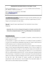
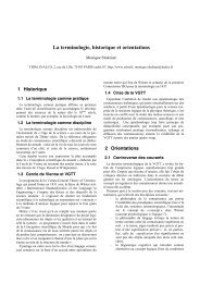
Without delving into the complexities <strong>of</strong> accurate mineralogical definitions, the four<br />
most common rock types used can be presented thus (fig. 1):<br />
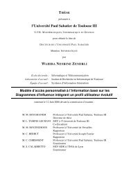
• Sedimentary rocks, which include numerous varieties <strong>of</strong> flints (fig. 1 : 1, 2 <strong>and</strong> 7),<br />
cherts, some limestones, dolomitic rocks, s<strong>and</strong>stones, some jaspers that are genuine silicified<br />
pelites.<br />
• Such igneous rocks as are characterized by a microlithic or vitreous texture. Barring<br />
some fine-grained granites <strong>and</strong> diorites, they are mainly extrusive rocks, whose crystallization<br />
has been prevented or stopped by rapid cooling. They include rhyolites, trachytes, <strong>and</strong>esites,<br />
basalts, phonolites (fig. 1 : 6), ignimbrites <strong>and</strong> obsidians (fig. 1 : 3 <strong>and</strong> 4).<br />
• Metamorphic rocks such as quartzites (fig. 1 : 5).<br />
• A mineral (tectosilicate) <strong>of</strong> hydrothermal origin, which crystallizes at low temperatures<br />
<strong>and</strong> comes as polymorphous varieties : hyaline quartzes (isolated crystal, fig. 1 : 8), milky<br />
quartzes (crystal agglomerate), chalcedonies <strong>and</strong> agates (a microcrystalline concretionary form<br />
<strong>of</strong> quartz, variously coloured or b<strong>and</strong>ed).<br />
19
7 8<br />
Fig. 1 — Raw materials. 1 : b<strong>and</strong>ed Bergeracois flint, Dordogne. 2 : Touraine flint. 3 : blue-black<br />
obsidian, Zinaparo* Mexico. 4 : black <strong>and</strong> red mottled obsidian, Oregon, U.S.A. 5 : burgundyred<br />
quartzite, Tagus terraces, Portugal. 6 : grey-blue phonolite, Isenya, Kenya. 7 : putty-coloured<br />
Bergeracois flint, Dordogne, before <strong>and</strong> after heat treatment. 8 : hyaline quartz, Minas<br />
Gerais, Brazil (Atelier photo C.N.R.S., Meudon).<br />
20
2. Knappin g suitability o f hard rocks<br />
One should bear in mind that experimentation witnesses constant breakthroughs, <strong>and</strong> that<br />
the assessment <strong>of</strong> rocks' suitability for knapping progresses accordingly. Nevertheless, although<br />
we are perforce guided by what we currently know, our assessment <strong>of</strong> the knapping suitability<br />
<strong>of</strong> a particular rock must absolutely be based on experimental tests.<br />
2.1. A n experimenter' s viewpoin t<br />
Prehistoric people worked all the raw materials at their disposal, testing, selecting <strong>and</strong><br />
choosing them according to their knapping suitability, their abundance <strong>and</strong> their shape.<br />
The following presentation <strong>of</strong> raw materials takes absolutely no account <strong>of</strong> mineralogical<br />
or petrographical classifications; it is based solely on the knapping characteristics <strong>of</strong> different<br />
rock types, appreciated in the course <strong>of</strong> experimental tests. The viewpoint <strong>of</strong> a single experimenter<br />
could well be considered empirical. However, allowances made for minor details, most<br />
modern stone-knappers come to similar conclusions, even though some <strong>of</strong> them may attain a<br />
higher degree <strong>of</strong> pr<strong>of</strong>iciency in certain techniques <strong>and</strong> methods.<br />
The opinions pr<strong>of</strong>essed here concerning a few dozen materials are therefore those <strong>of</strong> a<br />
single experimenter, whose motivations differ from prehistoric man's. This does not purport to<br />
be a comprehensive survey <strong>of</strong> the question, for the varieties <strong>of</strong> rocks knapped by prehistoric<br />
workers are countless.<br />
One <strong>of</strong> the authors (J.T.) has applied the principle <strong>of</strong> trying out every conceivable<br />
technique on as many natural materials as possible (pressure <strong>and</strong> percussion debitage <strong>and</strong><br />
retouching, using stone, bone, wood, antler, ivory, etc.); this led to many attemps, which were<br />
not however pursued over a long period <strong>of</strong> time. At the moment, we are far from having<br />
exhausted all the possibilities <strong>of</strong> systematic experimentation to further our underst<strong>and</strong>ing <strong>of</strong><br />
knapped tools.<br />
We shall not re-examine the physical qualities that cause a material to be good or bad,<br />
such as elasticity, homogeneity or fragility 21<br />
. What we <strong>of</strong>fer is a basic global appreciation,<br />
bearing in mind however that homogeneity is the main prerequisite for regular debitage (as in<br />
st<strong>and</strong>ardized blade production, for instance) or long retouches.<br />
As a matter <strong>of</strong> fact, rocks can be placed on a continuum, <strong>and</strong> range from those with which<br />
"anything is possible" to those from which flakes can only be removed with difficulty. In order<br />
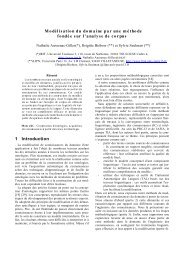
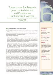
to clarify by simplifying, we propose three grades <strong>of</strong> suitability for knapping.<br />
• Rocks that are very easy to work. These fall into two main categories : vitreous <strong>and</strong><br />
fragile rocks, such as obsidian; non-vitreous <strong>and</strong> moderately fragile rocks, such as certain flints.<br />
• Rocks that are quite easy to work.<br />
• Rocks that are difficult to work.<br />
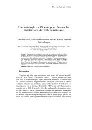
These three grades are shown in the table (fig. 2), as well as those resulting from heat<br />
treatment; it seemed both convenient <strong>and</strong> effective to thus sum up experiments for the<br />
manufacure <strong>of</strong>:<br />
- leaf-shaped bifacial pieces by percussion with a s<strong>of</strong>t hammer;<br />
- blades by direct percussion with a s<strong>of</strong>t hammer, or by indirect percussion;<br />
- blades by pectoral pressure with a crutch;<br />
- long parallel retouches by pressure.<br />
These appreciations must however be qualified.<br />
• The properties <strong>of</strong> some rocks may allow the application <strong>of</strong> certain techniques, while<br />
few good results, if any, will be achieved when other techniques are applied. For instance, very<br />
good h<strong>and</strong>axes, or even good thin leaf-shaped bifacial pieces, can be made from sanukite, a<br />
variety <strong>of</strong> <strong>and</strong>esite from Japan. On the other h<strong>and</strong>, the removal <strong>of</strong> flakes proves difficult, <strong>and</strong> the<br />
extraction <strong>of</strong> blades by percussion is virtually impossible.<br />
• A very few rocks require flaking "with the grain". For instance, the fossil wood from<br />
Tidikelt, in the Algerian Sahara, is much more easily worked if debitage follows the veins (fibres,<br />
in fact), which are still apparent - <strong>and</strong> that is precisely what the Aterians did.<br />
21 Crabtree, 1967.<br />
21
RAW MATERIALS<br />
EXPERIMENTS<br />
Obsidian<br />
(U.S.A., Japan, Icel<strong>and</strong>, Italy, Turkey,<br />
Greece, Kenya, Ethiopia, Mexico,<br />
Guatemala, Ecuador)<br />
bifacial<br />
pieces<br />
s<strong>of</strong>t<br />
hammer<br />
blades<br />
s<strong>of</strong>t<br />
hammer<br />
blades<br />
pressure<br />
parallel<br />
retouch<br />
pressure<br />
improvement<br />
heat<br />
treatment<br />
+ + + + + + + + -<br />
Ignimbrite (U.S.A.) + + + + + + -<br />
Resinite (France) + + / + -<br />
Quartz Crystal, Amethyst (France,<br />
Brazil)<br />
Translucent flin t<br />
(France, Engl<strong>and</strong>, Belgium, Denmark,<br />
Morocco, Algeria, Tunisia, Senegal,<br />
Lebanon, Qatar)<br />
Opaque flint<br />
(Europe, Africa, South-West Asia, North<br />
<strong>and</strong> South America)<br />
Chalcedony<br />
(France, Algeria, U.S.A.)<br />
+ + / / + -<br />
+ + + + + + + + +<br />
+ + + / + + +<br />
+ + + + + + + +<br />
Jasper (France, Greece, U.S.A.) + + + + / + + -<br />
Lydianstone (Algeria) + + / 1 + +<br />
Opali te (France) + + + + 1 + + + +<br />
Agate (Egypt, SouthAfrica) + / + + •<br />
Green "dacite" (Tenere / Niger) + + + + / + -<br />
Silicified wood (U.S.A., Algeria, Niger) + + / - + +<br />
Basalt (France, U.S.A., Brazil, Kenya) + - / + /<br />
"Sanukite" (Andesite) (Japan) + + - / + /<br />
Quarzite, S<strong>and</strong>stone<br />
(France,U.S.A., Algeria),<br />
Silicified "arenite " (Brazil)<br />
+ + + / + /<br />
Rhyolite (Algeria) + / - /<br />
Siliceous limestone (France, U.S.A.) + + / / -<br />
Novaculite (U.S.A.) + / / - + +<br />
Experiments : Heat treatment<br />
++ : very good ++ : very much improved<br />
+ : middling + : improved<br />
- : bad - : not improved<br />
/ : untested / : untested<br />
Fig. 2 — Knapping suitability tests.
• A single block <strong>of</strong> raw material may exhibit varying characteristics : the sub-cortical<br />
zones <strong>of</strong> some flints are perfectly suitable for the application <strong>of</strong> all techniques, whereas the inner<br />
stone is mediocre in quality.<br />
It is actually impossible to generalize concerning the suitability <strong>of</strong> a particular kind <strong>of</strong><br />
rock, such as flint for instance. And it is also sometimes difficult to voice a definite opinion about<br />
a regional type : the different outcrops or deposits yielding various sub-types must be examined<br />
(except in the case <strong>of</strong> river terraces) before any claim to accuracy can be made.<br />
As a rule, when faced with an archaeological problem, one should never prejudge the<br />
quality <strong>of</strong> a rock worked by prehistoric people. Each variety <strong>of</strong> rock, or even each nodule, can<br />
be considered as a unique case. The solution must always be found through experimentation.<br />
One should be careful not to be misled by materials whose knapping scars are difficult<br />
to read : they are not necessarily difficult to work. For instance, ripples <strong>and</strong> hackles are far less<br />
visible on a piece <strong>of</strong> coarse-grained quartzite than on a good homogeneous fine-grained flint.<br />
Both materials are however very easily worked.<br />
The aesthetic value <strong>of</strong> an object, as we appreciate it with our twentieth century eyes <strong>and</strong><br />
brain, is yet another matter where caution is required. Is a tool beautiful or ugly, well or badly<br />
made ? Or was there simply no other possibility, owing to the constraints imposed by the nature<br />
<strong>of</strong> the raw material <strong>and</strong> considering that the tool meets the end it was intended for ?<br />
An experimenter's comments<br />
• A rock must above all be homogeneous to be deemed suitable for knapping. As a direct<br />
consequence <strong>of</strong> lack <strong>of</strong> homogeneity, a seemingly high-grade lump <strong>of</strong> raw material can prove<br />
unworkable, except for the fashioning <strong>of</strong> very small pieces, owing to the presence <strong>of</strong> cracks or<br />
impurities (saccharoid nodules or feldspath crystals, bubbles, etc.). Frost induced internal joints<br />
<strong>and</strong> cracks are a particular hindrance when they are very common in a block, especially since<br />
they are not always immediately visible.<br />
• A rock that rings clear wherever it is struck st<strong>and</strong>s a good chance <strong>of</strong> being usable, <strong>and</strong><br />
is in any case not frost-damaged.<br />
• As a rule, the more translucent a rock, the greater its suitability, with the exception <strong>of</strong><br />
rock crystal.<br />
• There is little relation between the granularity <strong>of</strong> a rock <strong>and</strong> its suitability for<br />
knapping : some coarse-grained quartzites allow the production <strong>of</strong> leaf-shaped bifacial pieces.<br />
• A piece <strong>of</strong> raw material from which large blades can be struck <strong>of</strong>f by percussion allows<br />
the production <strong>of</strong> every shape attainable through percussion.<br />
• The more elastic the rock, the easier pressure debitage becomes, obsidian being a case<br />
in point.<br />
2.2. Hea t treatmen t o f ra w material s<br />
Although the great majority <strong>of</strong> rocks were used in their unaltered natural condition, a<br />
growing number <strong>of</strong> finds show that prehistoric knappers applied heat treatment to improve the<br />
quality <strong>of</strong> some raw materials <strong>and</strong> make knapping easier.<br />
Long considered a Solutrean invention, which was not adopted (or so it seems) by later<br />
Upper Palaeolithic cultures, heat-treating was first recognized on pressure-retouched pieces.<br />
Experimentation has shown empirically that pressure-retouching <strong>of</strong> some types <strong>of</strong> siliceous rocks<br />
was clearly made easier by heating : flint responds very favourably to such treatment (removals<br />
split <strong>of</strong>f more smoothly), whereas no (or little) improvement can be observed for quartzite, jasper,<br />
dacite, etc. 22<br />
. Evidence for heat-treating in the case <strong>of</strong> pressure debitage has in recent years been<br />
claimed first for Neolithic cultures 23<br />
, but also for such cultures <strong>of</strong> the Siberian Upper Palaeolithic<br />
22 Inizan, Roche, Tixier, 1975-76 : this paper was the first to bridge the gap between experimentation <strong>and</strong><br />
archaeological observation. Later references include Griffiths et al., 1987 ; Domanski, Webb, 1992 ; Borradaile et al.,<br />
1993.<br />
23 Binder, 1984; Inizan, Lechevallier, 1985.<br />
23
as used the said debitage technique 24<br />
. So far, the evidence concerns the production <strong>of</strong> bladelets<br />
alone; no blades <strong>and</strong> no blade-cores bearing witness to heat treatment have to this day been<br />
documented.<br />
As with pressure debitage, we are indebted to D. Crabtree for the recognition <strong>of</strong> this<br />
technique 25<br />
, which consists in heating siliceous rocks such as flint, chert <strong>and</strong> chalcedony to a<br />
temperature lying between 250°C <strong>and</strong> 350°C (480°F <strong>and</strong> 660°F). During the Lithic <strong>Technology</strong><br />
Congress held at Les Eyzies in 1964, this accomplished experimenter presented <strong>and</strong> demonstrated<br />
different types <strong>of</strong> pressure retouches achieved on siliceous rocks previously subjected to<br />
heat-treating 26<br />
. "Prehistorians-knappers" alone were enthralled by his work, <strong>and</strong> F. Bordes 27<br />
brought the matter up again as early as 1969.<br />
For heat treatment to be fully effective, the elevation in temperature <strong>and</strong> even more so<br />
the subsequent cooling must be very gradual; evidence for this has been claimed as much from<br />
contemporary examples - Khambhat, in the Gujarat (India) 28<br />
- as from experimental work. The<br />
current principle, still obtaining in India <strong>and</strong> in Yemen for the treatment <strong>of</strong> chalcedonies, can<br />
readily be contemplated for earlier periods. Lumps <strong>of</strong> rough or already shaped stone are first<br />
buried in ash, under a heap <strong>of</strong> fuel (sawdust or charcoal, dung, etc.), which is left to smoulder<br />
for a number <strong>of</strong> hours; the stones are taken out only after complete cooling. The entire operation<br />
takes about 24 hours. In an archaeological context, it would <strong>of</strong> course be extremely difficult to<br />
identify hearths that were used for that purpose, since siliceous rocks can be efficiently<br />
heat-treated in multiple function hearths, such as cooking hearths. The only indisputable example<br />
<strong>of</strong> the use <strong>of</strong> structures for heating flint nodules comes from a Neolithic site <strong>of</strong> central India, in<br />
the Son valley 29<br />
. Heat treatment was carried out in each <strong>of</strong> the six horizons <strong>of</strong> the Khunjun site,<br />
the cores were pressure-flaked <strong>and</strong> the resulting bladelets were used as blanks for geometrical<br />
microliths.<br />
In order to assess the expanse <strong>of</strong> this technique <strong>and</strong> the end(s) it was devised to meet,<br />
one must necessarily be capable <strong>of</strong> recognizing heat-treated products. There are two essential<br />
recognition criteria:<br />
- heating changes the colour <strong>of</strong> some rocks, depending on the amount <strong>and</strong> the type <strong>of</strong><br />
metallic oxides they contain (propensity towards rubefaction) (fig. 1:7);<br />
- although the outside <strong>of</strong> the rock appears unchanged except for its colour, any breakage<br />
or removal taking place after heat treatment will expose a shiny, greasy surface, in stark contrast<br />
to its former dull aspect (fig. 68).<br />
Minor accidents, such as the fine cracks <strong>of</strong>ten observed on chalcedonies <strong>and</strong> carnelians,<br />
also help to confirm the existence <strong>of</strong> deliberate heat-treating.<br />
Although this technique, improving the nature <strong>of</strong> the stone, was not adopted <strong>and</strong><br />
perpetuated by all groups after its invention, we have clear examples <strong>of</strong> its persistence. The heat<br />
treatment <strong>of</strong> carnelian, such as it is still practised in the traditional bead-making workshops <strong>of</strong><br />
Khambhat in India, <strong>and</strong> in Yemen, testifies in all likelyhood to the unbroken transmission <strong>of</strong> a<br />
prehistoric knowledge, since the technique has been applied to the same material for more than<br />
7000 years in the Indo-Pakistani sub-continent. From the Neolithic onwards, it has in the same<br />
region also been applied to pressure-flaked flints <strong>and</strong> chalcedonies. In the case <strong>of</strong> carnelian,<br />
heating fulfills both an aesthetic <strong>and</strong> a technical purpose *. not only does it improve the knapping<br />
characteristics <strong>of</strong> the stone, but it also alters the colour.<br />
Clearly, it behoves us now to be systematic in our efforts to detect this technique in the<br />
industries where pressure is used (either for debitage or for retouching). This can be done by<br />
looking for the stigmas previously described, bearing in mind that experimentation <strong>and</strong><br />
ethnographic observations can further our recognition <strong>of</strong> the phenomenon.<br />
24 Flenniken, 1987.<br />
25 Crabtree, Butler, 1964.<br />
26 Smith, 1966a.<br />
27 Bordes, 1969.<br />
28 Posselh, 1981.<br />
29 Clark <strong>and</strong> Khana, 1989.<br />
24
Raw material procuremen t strategie s<br />
<strong>Knapped</strong> hard rocks have deliberately been presented from the point <strong>of</strong> view <strong>of</strong> the<br />
experimenter. It is however equally important to take account <strong>of</strong> all the observations concerning<br />
the provenance <strong>of</strong> raw materials, their availability, their abundance, their use, etc. Research into<br />
such matters may result not only in the analysis <strong>of</strong> economic systems, but also in the development<br />
3 0<br />
<strong>of</strong> behavioural perspectives (ch. 6) . Indeed, the study <strong>of</strong> raw material distributions has in recent<br />
years proved a fruitful approach for tackling the question <strong>of</strong> territories, zones <strong>of</strong> influence,<br />
exchange <strong>and</strong> social interaction, etc.<br />
The systematic sourcing <strong>of</strong> raw materials, through intensive surveys, is <strong>of</strong> course (even<br />
if this seems to go without saying) the first necessary step. This approach is not new; it developed<br />
at the end <strong>of</strong> the XlXth century, but concerned mainly polished stone, petrographically different<br />
from knapped stone; indeed with the advent <strong>of</strong> the Neolithic, the need for hard-wearing stone<br />
(generally <strong>of</strong> metamorphic origin), suitable for polishing <strong>and</strong> guaranteeing efficient cutting<br />
edges, brought about a quest for new materials set in new geological contexts. More recently,<br />
research has focused on other exotic raw materials, such as obsidan <strong>and</strong> its distribution (see for<br />
instance the many articles concerning Mesoamerica, Greece, circum-Mediterranean regions <strong>and</strong><br />
the Near East, published over the last thirty years). This distinctive vitreous rock is easy to<br />
identify in any lithic assemblage, <strong>and</strong> can therefore unambiguously be termed exotic when the<br />
geological source is known to be far away. However, provenance studies should not be restricted<br />
to prestigious <strong>and</strong> exceptional materials alone, <strong>and</strong> the same emphasis must from now on be laid<br />
on all the mineral raw materials observed, even if they appear to be local. For it is important to<br />
decipher prehistoric people's attitude towards the materials they relied upon for their subsistance<br />
: stone is one <strong>of</strong> them, whatever its nature <strong>and</strong> its geological origin, <strong>and</strong> is furthermore<br />
unique in enduring nearly unaltered through time.<br />
Moreover, unfounded assumptions about human psychological development have too<br />
<strong>of</strong>ten been made : the more man develops, the more he makes choices, selects <strong>and</strong> transports, <strong>and</strong><br />
the less he allows himself to be dominated by environmental constraints. This assertion is<br />
probably true where general trends are concerned, but should be qualified according to each<br />
period, each region <strong>and</strong> each site, taking into consideration a growing number <strong>of</strong> parameters,<br />
which should throw light on raw material procurement strategies in particular.<br />
The questions that must be asked before attempting any kind <strong>of</strong> inquiry into economic<br />
or social behaviour pertain to the natural environment <strong>and</strong> also to the requirements <strong>of</strong> the culture<br />
under study.<br />
• The sourcing <strong>of</strong> raw materials <strong>and</strong> the appreciation <strong>of</strong> the manner in which past<br />
l<strong>and</strong>scapes may have shaped the patterning <strong>of</strong> movements across the territory belong to the realm<br />
<strong>of</strong> the earth sciences. In this respect, answers to the following questions can help to dismiss some<br />
environmental constraints, <strong>and</strong> thereby bring choices to light.<br />
- What is the geological context <strong>of</strong> occurrence? Is the raw material locally rare, or<br />
abundant?<br />
- Is there only one sort <strong>of</strong> raw material, or are there several varieties ?<br />
- Is the raw material easy, or on the contrary difficult, to collect or extract ?<br />
- What is its quality, in what shapes <strong>and</strong> sizes does it occur?<br />
- Could it be easily transported in its original shape?<br />
• On the other h<strong>and</strong>, prehistoric man has tasks to accomplish, requirements to meet,<br />
different levels <strong>of</strong> technical abilities, <strong>and</strong> cultural traditions to respect, all <strong>of</strong> which can also be<br />
expressed in terms <strong>of</strong> preferences, or even constraints. The analysis <strong>of</strong> raw material procurement<br />
strategies, following from the study <strong>of</strong> lithic industries, must enable one to explain specifically<br />
cultural traits.<br />
30 There is a wealth <strong>of</strong> literature on this subject, so that we have chosen to mention only a few <strong>of</strong> the more recent<br />
publications, particularly well documented <strong>and</strong> referenced: Demars, 1982 <strong>and</strong> Geneste, 1991 for the Palaeolithic <strong>of</strong><br />
the Aquitaine Basin; Floss, 1994 for the Palaeolithic <strong>of</strong> the Rhinel<strong>and</strong>; Feblot-Augustins, 1997 for the Palaeolithic <strong>of</strong><br />
western <strong>and</strong> central Europe as well as for earlier African industries; for the question <strong>of</strong> flint-mining in the Neolithic,<br />
see Pelegrin <strong>and</strong> Richards (eds), 1995. The reader will find additional references in the different Flint Symposium<br />
papers published over the last ten years.<br />
25
The deceptively simple problems mentioned above evoke a multiplicity <strong>of</strong> answers, some<br />
<strong>of</strong> them quite complex or interrelated, <strong>and</strong> give rise to a wide range <strong>of</strong> hypotheses. A cursory<br />
theoretical examination <strong>of</strong> three major issues will be made.<br />
1. Provenance o f raw materia l<br />
A single region may yield both numerous <strong>and</strong> varied deposits (natural geological<br />
sections, outcrops, seams, colluvial deposits, alluvial cones, volcanic flows, fluvial terraces,<br />
moraines, marine deposits, etc.). One should also bear in mind that raw material accessibility may<br />
have varied through time, depending on the modifications <strong>of</strong> the geological l<strong>and</strong>scape.<br />
The accurate sourcing <strong>of</strong> raw materials makes it possible to appreciate the lithic<br />
procurement territory <strong>of</strong> each palaeoethnic group. The next step is the assessment <strong>of</strong> the methods<br />
<strong>of</strong> procurement, such as surface collection, outcrop quarrying, mining <strong>and</strong> so on.<br />
2. Local availabilit y o f raw materia l<br />
The presence or absence <strong>of</strong> workable hard rocks close to prehistoric sites is in itself a<br />
highly informative element, <strong>of</strong> great complexity.<br />
The absence <strong>of</strong> any such rocks is rare, but their presence (provided they were accessible<br />
to prehistoric man) gives rise to many interpretations, which necessarily involve the dimensions,<br />
<strong>and</strong> sometimes the morphology, <strong>of</strong> the tools produced.<br />
However, the most common alternative is the following.<br />
• Hard rocks available in a form permitting the production <strong>of</strong> any desired blank, for<br />
instance blades, bladelets, large pieces, etc. As a corollary, does the site correspond to an<br />
occupation directly connected with the richness <strong>of</strong> the outcrop ? If the site proves to be only a<br />
workshop the answer will be straightforward, but rather less so if the site includes living areas<br />
as well as working areas.<br />
• Rocks available in a form suitable for specific tool morphologies, or nature <strong>of</strong> raw<br />
material adequate only for the manufacture <strong>of</strong> a limited range <strong>of</strong> tools. Thus, it is not infrequent<br />
that, in the same region, different raw material sources should be exploited by successive groups.<br />
For instance, in the Ténéré, at the Adrar Bous (Niger), cultures far apart in time occupied the<br />
same geographic location, but the Aterians used the local dark-gray microgranular rock to a far<br />
greater extent than the Neolithic inhabitants, who sought the well known "green stone" (dacite)<br />
outcrops, although they occurred dozens <strong>of</strong> miles away from most Neolithic living sites. A<br />
technical explanation is a possibility, since the green stone used by the Neolithics for the<br />
manufacture <strong>of</strong> their projectile points was suitable for bifacial retouching.<br />
In a general way, differences in raw material use can only be ascribed to tradition if all<br />
other natural constraints have been taken account <strong>of</strong>. Other explanations involving, for instance,<br />
changing l<strong>and</strong>scapes or the deterioration <strong>of</strong> the locally available rocks must not be dismissed.<br />
3. Transpor t t o the campsit e<br />
Another line <strong>of</strong> research has long been foreseen, but has only recently developed. This<br />
deals with the transport <strong>of</strong> raw materials to the campsite. As a first step, the constraints imposed<br />
by the sources <strong>of</strong> supply themselves should be assessed, in terms <strong>of</strong> accessibility, ease <strong>of</strong><br />
extraction <strong>and</strong> transport. When faced with flake-cores, first consider whether the raw material in<br />
its natural form could be transported or not, before assuming a cultural motivation.<br />
The following questions should then be asked. Was the raw material transported as<br />
unworked or initially roughed out blocks ? Were the preforms <strong>and</strong>/or cores prepared at the source<br />
itself? Were the tools produced at the site or were they fashioned elsewhere <strong>and</strong> then<br />
subsequently transported as end-products ?<br />
Partial answers can be given to these questions by examining the artefacts with an eye<br />
for technology : by assessing, for instance, the proportions <strong>of</strong> cortical surfaces or the relative<br />
quantities <strong>of</strong> characteristic debitage <strong>and</strong> bifacial-knapping waste products, <strong>and</strong> above all by<br />
refitting (ch. 6).<br />
26
unmodified<br />
block<br />
roughed ou t or<br />
preformed<br />
shaped out<br />
cores<br />
roughing ou t<br />
<strong>and</strong> shapin g<br />
•<br />
bifacial piece s<br />
out flake s after<br />
products<br />
• • • • • •<br />
debitage<br />
A m<br />
cores<br />
during or<br />
characteristic<br />
flakes<br />
unretouched<br />
knapping<br />
finished<br />
B o m • • • • • •<br />
c o m o o @ • • •<br />
D o o o o o o • •<br />
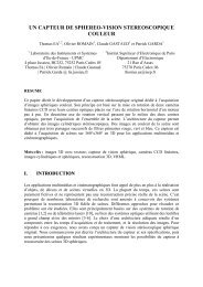
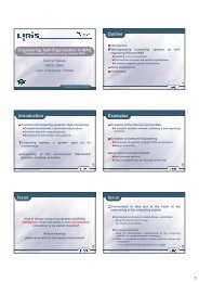
0 mus t b e presen t ma y be presen t O l<br />
Fig. 3 — Raw material procurement strategies.<br />
tools<br />
eft n e a r<br />
"quarr y site "<br />
There are many ways in which the transport <strong>of</strong> raw materials to campsites can be<br />
theoretically contemplated, <strong>of</strong> which four are here considered (fig. 3) :<br />
A - the material is brought to the campsite in its more or less original unworked condition<br />
(unmodified or tested by just one or two removals) ;<br />
B - the material is brought to the campsite as prepared cores (unflaked) <strong>and</strong>/or roughouts<br />
<strong>of</strong> bifacial pieces (unfinished) ;<br />
C - only unretouched debitage products <strong>and</strong>/or preforms <strong>of</strong> bifacial pieces are brought to<br />
the campsite ;<br />
D - only the tools (whether retouched or not) <strong>and</strong> the finished bifacial pieces are brought<br />
to the campsite.<br />
Each <strong>of</strong> these possibilities or "strategies" can be detected when conditions allow, <strong>and</strong> can<br />
be plausibly suspected in almost all major archaeological excavations. It is simply a matter <strong>of</strong><br />
noting the presence <strong>of</strong> well represented categories (fig. 3) <strong>of</strong> technically well defined pieces. The<br />
possible presence <strong>of</strong> other categories is not a contradictory factor, provided their occurrence is<br />
sporadic.<br />
As the various technical stages in the chaîne opératoire are not always fully carried out,<br />
it is necessary to add the following points to the categories <strong>of</strong> objects in the table :<br />
- rough blocks : including slightly modified ;<br />
- shaped out cores : including simply roughed out ;<br />
- roughing out <strong>and</strong> shaping out flakes : cortical flakes (quite numerous) <strong>and</strong>, where cores<br />
are concerned, crest-preparation flakes ; first flakes can be quite rare finds ;<br />
- cores : at different stages <strong>of</strong> knapping ;<br />
- flakes, pieces characteristic <strong>of</strong> a debitage technique or method : crests, flakes resulting<br />
from the preparation <strong>and</strong> rejuvenation <strong>of</strong> pressure or striking platforms ;<br />
- finished tools : unretouched blanks in some cases (Levallois; blanks used without<br />
further modification), or retouched, or in the case <strong>of</strong> bifacial pieces, finished.<br />
In each case, the complement can be assumed to have remained near the outcrops.<br />
27
Chapter 2<br />
Knapping<br />
Intentional knappin g<br />
The purpose <strong>of</strong> knapping is to make tools, in the broader sense <strong>of</strong> the term. Knapping<br />
will always leave similar scars on stone artefacts, irrespective <strong>of</strong> whether they are the work <strong>of</strong><br />
the earliest hominids, or elaborate Bronze Age dagger blades from Denmark. Even if they are<br />
almost modern, like the many tinderboxes recently discovered on late Islamic sites, the scars will<br />
not differ. The technological interpretation <strong>of</strong> any worked stone artefact will therefore be specific<br />
to that artefact, <strong>and</strong> based on the precise observation <strong>and</strong> recognition <strong>of</strong> those scars. A stone<br />
artefact can only be defined as such by removal scars, both positive <strong>and</strong> negative. Resulting from<br />
either pressure or percussion, such scars obey physical laws <strong>and</strong> are identical whether knapping<br />
is intentional or not.<br />
The diagnosis <strong>of</strong> intentional knapping is best vindicated when the artefacts are discovered<br />
in a well defined archaeological context. In the case <strong>of</strong> chance discoveries or surveys, the<br />
main criteria for recognizing intentional knapping is the organization <strong>of</strong> removals. Caution is<br />
required when flakes or even "pebble-tools" are found on a beach, for they may well result from<br />
natural phenomena; to the contrary, the discovery <strong>of</strong> a single h<strong>and</strong>axe or a single Levallois core<br />
can prove intentional knapping : the organization <strong>of</strong> removals follows so specific a sequence that<br />
the possibility <strong>of</strong> chance "knapping" due to r<strong>and</strong>om impacts can be dismissed. The number <strong>of</strong><br />
pieces found <strong>and</strong> their geological position provide additional information concerning the context<br />
<strong>and</strong> further help to establish the possible presence <strong>of</strong> a site. However, one must bear in mind that<br />
it is not always easy to distinguish intentional from unintentional knapping, <strong>and</strong> the question<br />
<strong>of</strong>ten arises as to whether the modifications reflect intent or accident.<br />
29
Knapping, shaping, flaking, retouchin g<br />
Whichever way the stone-knapper goes about his work, he must use a set <strong>of</strong> tools, <strong>and</strong><br />
these are presented in the appended lexicon (fig. 72 <strong>and</strong> fig. 73).<br />
The term "knapping" has a general meaning, <strong>and</strong> applies to any type <strong>of</strong> action aiming at<br />
intentionally fracturing raw material. Knapping encompasses shaping, retouching <strong>and</strong> debitage<br />
(or flaking), which are each used in a more restrictive sense. These terms describe precise actions,<br />
<strong>and</strong> are dealt with in separate chapters. The word knapping is used when a more accurate one<br />
cannot be applied. This happens when the use <strong>and</strong> purpose <strong>of</strong> a knapped artefact cannot be clearly<br />
defined : for instance, is a chopper a core, an actual tool, or both ?<br />
Knapping methods <strong>and</strong> technique s<br />
The importance <strong>of</strong> distinguishing between these two terms was pointed out as early as<br />
1965 during an international symposium 31<br />
. By definition, knapping methods <strong>and</strong> techniques<br />
concern shaping, flaking <strong>and</strong> retouching.<br />
Method refers to any carefully thought out sequence <strong>of</strong> interrelated actions, each <strong>of</strong><br />
which is carried out according to one or more techniques. More <strong>of</strong>ten than not, the term method<br />
implies an elaborate conceptual scheme leading to the manufacture <strong>of</strong> predetermined products,<br />
whether by shaping or by flaking. Clearly, what must be identified is predetermination.<br />
The main methods currently acknowledged are defined in chapters 3, 4 <strong>and</strong> 5.<br />
Physical actions - a deft flip <strong>of</strong> the h<strong>and</strong>, the use <strong>of</strong> a hard or s<strong>of</strong>t hammer, the<br />
interposition <strong>of</strong> a punch - are all examples <strong>of</strong> techniques. Thanks to major breakthroughs in<br />
experimentation, knapping techniques are now well identified. The criteria used derive from<br />
observations made on archeological assemblages, which are then substantiated by experimentation.<br />
Special retouching techniques are treated in chapter 5.<br />
Technical procedures are short systematic sequences <strong>of</strong> actions involved in any kind <strong>of</strong><br />
preparation, such as : the abrasion <strong>of</strong> an overhang, the preparation <strong>of</strong> an edge prior to removal<br />
by a burin blow, the facetting <strong>of</strong> a striking or pressure platform, the preparation <strong>of</strong> a spur.<br />
The main technique s<br />
1. Percussio n<br />
Application <strong>of</strong> force to fracture raw materials.<br />
Direct percussion<br />
• Direct percussion with a stone hammer (hard or s<strong>of</strong>t stone) (fig. 4) <strong>and</strong>, theoretically,<br />
its symmetrical opposite, percussion <strong>of</strong> an artefact on an anvil, are the main expressions <strong>of</strong> this<br />
technique. Various knapping techniques were invented through the ages, but the first undoubtedly<br />
was direct percussion with a hard hammerstone. For hundreds <strong>of</strong> thous<strong>and</strong>s <strong>of</strong> years, it was the<br />
only technique applied, <strong>and</strong> its use endured throughout the history <strong>of</strong> stone-knapping. It can<br />
therefore never be used as a chronological argument.<br />
Direct percussion with a s<strong>of</strong>t hammerstone is suitable for the shaping <strong>of</strong> bifacial preforms<br />
<strong>and</strong> for the removal <strong>of</strong> moderately regular blades 32<br />
. The materials chosen for this type <strong>of</strong> hammer<br />
include s<strong>of</strong>t s<strong>and</strong>stones or cornstones, which tend to crumble on impact. Comparable results<br />
31 We draw attention to the unwarranted use <strong>of</strong> the term "technological" where "technique" or "method" are more<br />
appropriate. A symposium organized by the Wenner-Gren foundation was held at Burg Wartenstein (Austria), during<br />
which several prehistorians discussed those problems <strong>of</strong> terminology (e.g. Balout, 1967 <strong>and</strong> Tixier, 1967).<br />
32 Crabtree, 1972; Madsen, 1983 ; Pelegrin, 1991a.<br />
30
Fig. 4 — Knapping techniques. 1 : direct percussion using a stone hammer. 2 : direct percussion using<br />
an antler billet. 3 : indirect percussion (antler punch, wooden billet). 4 : indirect percussion by<br />
counter-blow. 5 : pressure with a short pelvic crutch. 6 : pressure in the h<strong>and</strong> (parallel<br />
retouches).<br />
31
could not be reached with such other currently used rocks as quartzites, basalts, flints, etc., which<br />
are harder <strong>and</strong> more resistant.<br />
• Direct percussion with a s<strong>of</strong>t hammer (wood, antler, bone, ivory, etc.) occurs later in<br />
time (fig. 4 : 2). Evidence for this technique dates back to 700 000 years in Africa, but it probably<br />
appeared even earlier.<br />
Indirect percussion<br />
• Indirect percussion, in the accepted meaning <strong>of</strong> the word, involves the application <strong>of</strong><br />
an intermediary tool, called punch, which can be <strong>of</strong> wood, antler, bone or metal (fig. 4 : 3). There<br />
is no indisputable evidence for this technique before the Mesolithic.<br />
• Indirect percussion by counter-blow (fig. 4 : 4) is used today in Khambhat (Gujarat,<br />
India) 33<br />
to make carnelian <strong>and</strong> agate beads <strong>and</strong> trinkets. The piece to be knapped is held in the<br />
h<strong>and</strong>, touching the end <strong>of</strong> a pointed iron rod stuck in the ground; the opposite side <strong>of</strong> the stone<br />
is then struck with a buffalo-horn-topped hammer; the flake is removed by the counter-blow <strong>of</strong><br />
the pointed iron rod. It is a remarkably effective technique, <strong>and</strong> could have been invented in<br />
prehistoric times, or at least when bronze appeared.<br />
2. Pressur e<br />
Application <strong>of</strong> pressure to fracture raw materials (fig. 4 : 5 <strong>and</strong> 6).<br />
• Pressure is applied with the narrow end <strong>of</strong> a tool made <strong>of</strong> wood, antler, bone or metal.<br />
This debitage <strong>and</strong> retouching technique was invented in the Upper Palaeolithic. There are many<br />
different ways in which pressure can be applied (chap. 4, p. 76; fig. 30).<br />
• Pressure with a lever<br />
Considerable pressure (300 kg) can be exerted when a lever is used. This technique has<br />
only recently been experimented 34<br />
, <strong>and</strong> is suggested to have been used for the production <strong>of</strong> the<br />
outsize (up to 41 cm) Varna type <strong>of</strong> blades 35<br />
. It appears quite late in time, in the Chalcolithic <strong>and</strong><br />
the Bronze Age, <strong>and</strong> is possibly connected with the use <strong>of</strong> copper.<br />
Knapping product s<br />
The expression "knapping products" has a general meaning, which does not prejudge<br />
their possible final use. Knapping products are thus, in a broad sense, flakes (for the moment<br />
there is no need to be more specific) produced by any knapping operation.<br />
Once knapping is shown to involve the production <strong>of</strong> blanks, these are known as debitage<br />
products. If <strong>and</strong> when a knapping product can be situated in its chaîne opératoire, it should be<br />
specified whether it is : a flake (lato sensu) resulting from the shaping out <strong>of</strong> a core ; a flake<br />
resulting from the shaping <strong>of</strong> a h<strong>and</strong>axe ; or a retouch flake, etc.<br />
It is only after having studied the tools <strong>and</strong> the production <strong>of</strong> blanks that one may apply<br />
the more restrictive term "knapping waste products" to the residue <strong>of</strong> material that is obviously<br />
not predetermined, not retouched, <strong>and</strong> not conceived as tool blanks (even though any ordinary<br />
flake is always a potential blank).<br />
33 Possehl, 1981 ; Roux, Pelegrin, 1989.<br />
34 Pelegrin, 1988 : 48; Volk<strong>of</strong>, Guiria, 1991.<br />
35 See Pelegrin's diagnosis in : Manolakakis, 1994.<br />
32
1. Describing a flake<br />
Removals from any lump <strong>of</strong> raw material produce flakes that share a number <strong>of</strong><br />
characteristics, determined by the propagation <strong>of</strong> fracture waves in hard rocks. The following<br />
descriptions concern only such rocks as show conchoidal fractures, since they are chiefly the ones<br />
that were knapped throughout prehistory.<br />
Whichever technique was applied to remove the flake, the identification <strong>of</strong> the latter as<br />
such is contingent upon the reading <strong>of</strong> fracture scars (fig. 5):<br />
- on the lower (ventral) face or flaking face, or more accurately fracture face (the<br />
opposite face being called the upper (dorsal) face): percussion or pressure ripples, bulb, hackles,<br />
etc.;<br />
- on the butt (i.e. the part removed from the striking or pressure platform): traces <strong>of</strong><br />
preparation, impact point, etc.<br />
It is relative to these two main elements that an unretouched flake is conventionally<br />
oriented, butt downwards. Butt <strong>and</strong> bulb can however be missing, in which case the flake can<br />
only be oriented if the other fracture scars are visible on the lower face : percussion or pressure<br />
Fig. 5 — Main descriptive terms for flakes.<br />
33
ipples, hackles (see p. 142). Paradoxically, while a flake is identified as such by its lower face,<br />
the left <strong>and</strong> right edges are designated in terms <strong>of</strong> the upper face following a conventional<br />
orientation, proximal part downwards (fig. 5).<br />
Blades <strong>and</strong> bladelets are only morphologically different from flakes, <strong>and</strong> for them to be<br />
counted as such they must be at least twice as long as they are wide.<br />
2. Characteristi c flakes<br />
Characteristic flakes are flakes that can without any ambiguity be mentally situated in<br />
the chaîne opératoire (fig. 8, 9 <strong>and</strong> 10), thanks to their distinctive features. They can result from<br />
shaping (bifacial-knapping flakes), debitage (crests, core-rejuvenation flakes) or retouching<br />
(Clactonian notch flake). The initial flake is universal : all knapping operations must yield a first<br />
flake, which is also characteristic.<br />
3. Knapping wast e product s<br />
This category concerns all the flakes or flake fragments that do not seem to have any<br />
possible use <strong>and</strong>/or cannot be situated in the chaîne opératoire.<br />
• Characteristic waste products : although small, they belong to the category <strong>of</strong> characteristic<br />
flakes. Their presence can be indicative <strong>of</strong> specific knapping activities. A retouch flake<br />
from a small bifacial projectile point is a characteristic waste product.<br />
• Debris : applies to any shapeless fragment, when the means by which it was fractured<br />
cannot be identified. A distinction must further be drawn between a debris <strong>and</strong> a broken<br />
fragment : while in the latter case the original object can be reconstituted, in the former it cannot.<br />
4. Knapping accident s<br />
A knapping accident, which may occur during flaking, shaping or retouching, is an<br />
unforeseen <strong>and</strong> unintentional incident generating products with a specific morphology 36<br />
.<br />
Archaeologically observed <strong>and</strong> experimentally produced knapping accidents are identical, thus<br />
strengthening the credibility <strong>of</strong> the analogy-based experimental approach.<br />
They come as a certain number <strong>of</strong> "types", <strong>and</strong> are due either to flaws in the raw material<br />
(joints, vesicles, saccharoid nodules, etc.) or to some mismanagement on the knapper's part.<br />
Knapping accidents have varying repercussions on the continuation <strong>of</strong> the knapping<br />
sequence to which they belong. They can be irreversible (fracture <strong>of</strong> a large leaf-shaped bifacial<br />
piece, plunging Levallois point, etc.), put right (hinged blade removed from a core with two<br />
striking platforms : in that case, a single removal struck <strong>of</strong>f from the opposite platform is<br />
sufficient for debitage to proceed unimpaired), or <strong>of</strong> no consequence (bulb scars, fracture <strong>of</strong> a<br />
burin spall when the latter is a waste product, etc.).<br />
Although unintentionally obtained, the products resulting from knapping accidents can<br />
also be used as blanks.<br />
4.1. Break s<br />
Accidental snapping <strong>of</strong> a flake (lato sensu) upon removal, or <strong>of</strong> any artefact in the<br />
process <strong>of</strong> being knapped. The occurrence <strong>of</strong> breaks is irrespective <strong>of</strong> the technique employed<br />
(percussion, pressure, etc.), <strong>and</strong> the main types are listed hereafter.<br />
• Clean breaks, whose surface is perpendicular to the debitage axis <strong>and</strong> the lower face<br />
(fig. 6).<br />
• "Siret" accidental break : refers to the snapping in two <strong>of</strong> a flake along the debitage<br />
axis. Such accidents were long mistaken for burins ; they leave but a partial arris on the core<br />
(when it is at all visible), on the distal part <strong>of</strong> the removal negative (fig. 80).<br />
36 Roche, Tixier, 1982.<br />
34
Fig. 6 — Large blade with multiple breaks (clean breaks, languette, etc.). Experimental debitage, direct<br />
percussion using a wooden billet (J. T.), Gr<strong>and</strong>-Pressigny flint, Indre-et-Loire. The fragment<br />
outlined by a dashed line was not retrieved (Roche, Tixier, 1982 : fig. 1).<br />
35
• Languette 31<br />
breaks occurring on the lower or upper face; they can be simple ou<br />
double, in which latter case they sometimes generate characteristic waste products (fig. 7 : 2, 3<br />
<strong>and</strong> 4).<br />
• Nacelle breaks, initiated by bulb scars 38<br />
, which arch suddenly towards the upper face,<br />
removing part <strong>of</strong> the two edges, <strong>and</strong> then intersect quite as suddenly the lower face. The small<br />
waste product corresponding to the nacelle has a very specific shape (fig. 7:5). Such accidents<br />
are more common when pressure rather than percussion is applied.<br />
4.2. Plunging flake s<br />
They result from a phenomenon causing the fracture plane, whose proximal part is<br />
normal, to plunge suddenly away from the exterior surface <strong>and</strong> remove a whole section <strong>of</strong> the<br />
blank, be it a core, a debitage product or a tool (fig. 7 : 5 <strong>and</strong> fig. 74).<br />
4.3. Hinged flakes<br />
Hinged flakes are the opposite <strong>of</strong> plunging flakes, although they probably share the same<br />
physical causes (variation in the propagation speed <strong>of</strong> the fracture front). A hinged flake is a<br />
removal whose fracture plane, normal in its proximal part, arches suddenly <strong>and</strong> intersects<br />
prematurely the upper face <strong>of</strong> the blank, resulting in a rounded distal end (hinge-fracture) 39<br />
or<br />
an abrupt clean break (step-fracture). The blank is therefore shorter than what was expected<br />
(fig. 7:1; fig. 14 : 3).<br />
Hinged pieces <strong>and</strong> their removal negatives are very characteristic. It is the most common<br />
accident that befalls beginners when they try their h<strong>and</strong> at knapping.<br />
4.4. Miscellaneou s<br />
• Incipient fractures should be included in knapping accidents, as well as incipient bulbs<br />
<strong>and</strong> still adhering flakes or blades.<br />
• Lipped flakes.<br />
During the knapping <strong>of</strong> bifacial pieces or blades, <strong>and</strong> especially when direct percussion<br />
with a s<strong>of</strong>t hammer is applied, the flake or the blade may happen to remove a larger amount <strong>of</strong><br />
material than expected in the butt area. The result is a proximal part showing a very broad butt,<br />
an extremely diffuse bulb with a concave pr<strong>of</strong>ile <strong>and</strong> a postbulbar constriction. The removal<br />
negative, bearing some similarity to a Clactonian notch, disfigures the edge <strong>of</strong> the bifacial piece<br />
or the striking platform <strong>of</strong> the core. The specific nature <strong>of</strong> this accident lies in the fact that the<br />
fracture initiates far behind the impact point <strong>of</strong> the hammer. If they are not closely examined,<br />
such flakes can well be mistaken for plunging flakes. The occurrence <strong>of</strong> such an accident is<br />
irrespective <strong>of</strong> the raw material used.<br />
• "Parasitical" flakes<br />
Such flakes are either complementary (in the case <strong>of</strong> bulb scars, for instance, fig. 5) or<br />
supplementary ("splinter" chipped <strong>of</strong>f from the overhang <strong>of</strong> the striking platform, upon removal<br />
<strong>of</strong> a flake by percussion; the waste product is elongated, with a triangular cross-section, <strong>and</strong><br />
shows neither butt nor bulb).<br />
• "Spontaneous" removals<br />
These occur within a fraction <strong>of</strong> a second after the removal <strong>of</strong> a flake, when the latter<br />
cannot fall free because the core rests on the knapper's h<strong>and</strong>, foot or thigh, <strong>and</strong> are not easy to<br />
distinguish from the intentional removals resulting from retouching. They generally concern the<br />
distal end <strong>of</strong> the blank (short removals), but can also produce notches (or even denticulates) on<br />
the lateral edges 40<br />
.<br />
It is absolutely necessary to have a comprehensive knowledge <strong>of</strong> knapping accidents in<br />
order to :<br />
37 Bordes, 1970.<br />
38 Therefore, "dorsal nacelles" cannot exist.<br />
39 Crabtree, 1972 : 25.<br />
40 Newcomer, 1976.<br />
36
Fig. 7 — Experimental knapping accidents. 1 : hinged flake (aborted blade), direct percussion using an<br />
antler billet, Bergeracois flint, Dordogne. 2 : blade with a simple lower face languette, indirect<br />
percussion "under the foot", Goussainville flint, Oise. 3 : blade with a long upper face<br />
languette, indirect percussion, Idaho obsidian, U.S.A. 4 : "parasitical" flake between two<br />
opposite languettes. 5 : plunging bladelet with a lower face nacelle break, pressure debitage<br />
using a pectoral crutch, obsidian (Roche, Tixier, 1982 : fig. 3, 1).<br />
37
- distinguish intentional from unintentional knapping, which is crucial;<br />
- better underst<strong>and</strong> technical physical actions <strong>and</strong> their chronology, as well as the<br />
operative schemes brought into play; a burin that has been disfigured by a plunging spall need<br />
not be entirely discarded : the distal end <strong>of</strong> the negative <strong>of</strong> the spall can be used as a surface on<br />
which another burin blow will be applied to produce, for instance, a new dihedral burin;<br />
- better appreciate techniques through a comparison with modern experiments;<br />
- assess the knappers' degree <strong>of</strong> competence;<br />
- apprehend a tradition with greater confidence when accidents are linked to specific<br />
techniques.<br />
The observation <strong>of</strong> knapping accidents by prehistoric people probably caused them to<br />
master the phenomenon, thus converting it into something intentional: anyone trying to make a<br />
backed edge on a blade will sooner or later break it, accidentally producing a microburin or a<br />
"Krukowski" microburin. This technique was systematized long before the time <strong>of</strong> geometrical<br />
microliths, in the early Upper Palaeolithic <strong>of</strong> North Africa : more than 20000 years ago, it was<br />
applied in the Iberomaurusian to make La Mouillah points 41<br />
.<br />
Another example <strong>of</strong> the systematic use <strong>of</strong> accidents concerns the plunging Levallois<br />
flakes necessary to the manufacture <strong>of</strong> Tabelbala type cleavers 42<br />
: this ultimate technical action<br />
in the knapping sequence is a particularly original feature in the production <strong>of</strong> those Acheulean<br />
artefacts from the western Sahara <strong>and</strong> South Africa. Here, it would be disastrous not to achieve<br />
a plunging flake!<br />
41 Tixier, 1963 : 106.<br />
42 Tixier, 1956.<br />
38
Three knapping sequence s<br />
5<br />
8 — Bifacial shaping <strong>of</strong> an arrowhead with tang <strong>and</strong> wings, starting from a flake. 1 : unretouched<br />
flake. 2 : roughing out by percussion to thin the proximal end (bifacial removals) <strong>and</strong> reduce<br />
the curve <strong>of</strong> the distal end (inverse removals). 3 : achieving the preform by percussion. 4 :<br />
finishing by pressure. 5 : carving out the tang.<br />
39
Fig. 9 — Blade debitage carried out on a core with a single striking platform. 0 : unmodified block. 1 :<br />
summary shaping out, creation <strong>of</strong> a striking platform. 2 : removal <strong>of</strong> a first blade, entirely<br />
cortical. 3, 4 : successive removals <strong>of</strong> blades <strong>of</strong> plein debitage, with rejuvenation <strong>of</strong> the striking<br />
platform.<br />
40
Fig. 10 — Blade debitage carried out on a core with two opposite striking platforms. 0 : unmodified<br />
block. 1 : shaping out the core by means <strong>of</strong> an initial frontal crest (A) <strong>and</strong> two postero-lateral<br />
crests (B <strong>and</strong> C). 2 : creation <strong>of</strong> two opposite striking platforms. 3 : removal <strong>of</strong> two opposite<br />
crested blades. 4 : blade debitage with platform rejuvenation (piein debitage).<br />
41
Chapter 3<br />
Shaping<br />
We use the term shaping to indicate a sequence <strong>of</strong> knapping operations carried out for<br />
the purpose <strong>of</strong> manufacturing a single artefact by sculpting the raw material in accordance with<br />
the desired form. This particular knapping mode, which can be fitted into any <strong>of</strong> the phases <strong>of</strong> a<br />
chaîne opératoire, aims at creating a specific morphology, whether it be an arrowhead (whose<br />
function can be presumed), a h<strong>and</strong>axe (the use <strong>of</strong> which remains unknown), or the preform <strong>of</strong> a<br />
stone axe that will subsequently be polished.<br />
Although shaping applies mainly to bifacial pieces, it can concern other artefacts <strong>of</strong><br />
varied morphology, such as polyhedrons <strong>and</strong> spheroids, trihedrons, chisels, stone axes with<br />
square cross-sections, etc. Shaping also applies to the manufacture <strong>of</strong> preforms. However, when<br />
an operation akin to shaping is shown to belong really to a chaîne opératoire concerned with<br />
debitage, one speaks <strong>of</strong> a core being shaped out because the underlying concept is different. A<br />
case in point is the Japanese Yubetsu method for the production <strong>of</strong> bladelets (p. 79).<br />
With shaping, it is not always possible to say what was actually intented : the fashioning<br />
<strong>of</strong> a single tool or the production <strong>of</strong> blanks. Most chaînes opératoires concerned with shaping<br />
produce quite a number <strong>of</strong> flakes that can be used as blanks for flake tools. It is also <strong>of</strong>ten<br />
impossible to ascribe utilitarian properties to the artefacts resulting from shaping.<br />
Shaping is a mode <strong>of</strong> knapping that is very widespread, in both time <strong>and</strong> space, <strong>and</strong> has<br />
been applied to almost all the types <strong>of</strong> raw material suitable for knapping, from coarse-grained<br />
quartzite to obsidian.<br />
Finally, shaping encompasses a certain number <strong>of</strong> methods, each <strong>of</strong> which shows many<br />
variations. The following developments concern only some <strong>of</strong> the major methods : bifacial<br />
shaping, polyhedral <strong>and</strong> spheroidal shaping, trihedral <strong>and</strong> quadrangular shaping. Preforms, by<br />
definition an intermediate stage in a chaîne opératoire <strong>and</strong> not associated with any particular<br />
morphology, are dealt with in a separate section, as well as cleavers, a very special type <strong>of</strong> tool.<br />
43
Bifacial shapin g<br />
Bifacial shaping appeared in eastern Africa at the end <strong>of</strong> the Oldowan period, more than<br />
one <strong>and</strong> a half million years ago, <strong>and</strong> has virtually always been used ever since. The h<strong>and</strong>axe is<br />
an all-important feature <strong>of</strong> the Lower Palaeolithic. Although not omnipresent, it is - sometimes<br />
along with the cleaver - the best represented tool in Acheulean industries. It remains conspicuously<br />
present during the Middle Palaeolithic. In later periods, bifacial shaping appears or<br />
disappears depending on the culture. In the French Upper Palaeolithic, for instance, it reaches its<br />
apogee with the Solutrean, but is not taken up later by the Magdalenians. On the other h<strong>and</strong>, in<br />
other cultural contexts, such as Asia, bifacial shaping features in the technical background during<br />
the entire Upper Palaeolithic. As from the end <strong>of</strong> the Mesolithic <strong>and</strong> until metal appears, it<br />
becomes virtually universal owing to the development <strong>of</strong> projectile points.<br />
1. Methods<br />
Although the methods used for bifacial shaping vary considerably according to the<br />
different periods, the basic concept stays much the same. Differences appear only within the<br />
operative schemes, the techniques <strong>and</strong> the way in which they are applied. The bifacial concept is<br />
described here from a general point <strong>of</strong> view.<br />
Whichever way the original blank was obtained (it can, for instance be a large flake<br />
struck <strong>of</strong>f from a core), bifacial shaping can be divided into two phases, roughing out <strong>and</strong><br />
finishing.<br />
• Roughing out consists in the simultaneous fashioning <strong>of</strong> two more or less convex<br />
43<br />
surfaces on either side <strong>of</strong> a bifacial equilibrium plane (fig. 11 : A). This term is used in<br />
preference to plane <strong>of</strong> symmetry because the two surfaces - which define a contour, marked out<br />
by a ridge - are definitely not always symmetrical, <strong>and</strong> this applies in particular to h<strong>and</strong>axes.<br />
• Finishing consists in giving the contour a regular shape, according to a second bilateral<br />
equilibrium plane (fig. 11 : B), perpendicular to the bifacial equilibrium plane. Finishing bears<br />
some similarity to retouching, especially where small pieces made from flakes are concerned. It<br />
is this step that gives the artefact its final morphology, by delineating the edges, carving out a<br />
tang, or arrowhead wings, etc.<br />
Any blank can be shaped into a bifacial piece : a cobble, a block, a slab, a chunk <strong>of</strong> stone,<br />
<strong>and</strong> <strong>of</strong> course a flake (fig. 8). The closer the morphology <strong>of</strong> the blank is to the intended final<br />
shape, the less work is required to rough it out. In the case <strong>of</strong> a bifacial piece made from a thick<br />
block, it is necessary to do some preliminary flaking before roughing out can be undertaken : this<br />
entails flaking away the cortex <strong>and</strong> coming closer to the desired morphology. On the other h<strong>and</strong>,<br />
one or two generations <strong>of</strong> removals only are needed to shape a bifacial piece made from a flake.<br />
Some Acheuleans have systematically struck <strong>of</strong>f large, short <strong>and</strong> wide slightly déjeté flakes, to<br />
use as blanks for their h<strong>and</strong>axes : in that case, shaping is incorporated into a longer chaîne<br />
opératoire, which includes an initial flaking sequence that shows predetermination in the<br />
obtaining <strong>of</strong> blanks 44<br />
.<br />
2. Technique s<br />
Prehistoric people applied the main stone-knapping techniques to bifacial flaking as they<br />
successively invented or adopted them : direct percussion with a hard or s<strong>of</strong>t hammer, indirect<br />
percussion, pressure, pecking, <strong>and</strong> then polishing.<br />
As early as the middle Pleistocene, different techniques were brought into play for the<br />
fashioning <strong>of</strong> a single bifacial artefact : direct percussion with a stone hammer to first remove<br />
the blank <strong>and</strong> then rough it out, direct percussion with a s<strong>of</strong>t hammer to give the piece its final<br />
shape. These two operations generate characteristic flakes (fig. 14). The shift from one technique<br />
43 Texier, 1989; Roche, Texier, 1991.<br />
44 Texier, Roche, 1995b.<br />
44
to another in the course <strong>of</strong> roughing out <strong>and</strong> finishing is not systematic, but it does occur quite<br />
frequently. Unquestionable evidence for this practice dates back to 700000 years in eastern<br />
Africa, <strong>and</strong> it probably existed even earlier. In some long chaînes opératoires including preforms<br />
<strong>and</strong> belonging to more recent periods, it is not uncommon to see three, or even four different<br />
techniques used for the manufacture <strong>of</strong> a single artefact (see below).<br />
Fig. 11 — Bifacial (A) <strong>and</strong> bilateral (B) equilibrium planes <strong>of</strong> an h<strong>and</strong>axe.<br />
3. Morphologie s<br />
The morphologies <strong>of</strong> bifacially shaped objects can be very variable (figs. 12, 13, 37). The<br />
above mentioned distribution <strong>of</strong> volume during roughing out can tend towards symmetry on<br />
either side <strong>of</strong> the bifacial equilibrium plane, or remain asymmetrical. Likewise, the frontal view<br />
can be perfectly symmetrical bilaterally, or show an intended (or fortuitous) asymmetry.<br />
Some shapes remained morphotechnically stable over very long periods, like the<br />
Acheulean h<strong>and</strong>axe. Use-wear analysis is yet unable to identify the functional reasons for the<br />
success <strong>of</strong> the h<strong>and</strong>axe. However, it seems that its development was closely linked to the<br />
acquisition <strong>of</strong> the idea <strong>of</strong> symmetry (well mastered during the early Acheulean, one million years<br />
ago), even if far from always perfect, <strong>and</strong> also to the ability to flake large blanks.<br />
Other bifacial morphologies, on the other h<strong>and</strong>, result from specific conceptions with a<br />
limited existence in both time <strong>and</strong> space, like the Middle <strong>and</strong> Upper Solutrean laurel-leaves,<br />
whose function, once again, can only be surmised. That <strong>of</strong> projectile points can be more readily<br />
appreciated : their morphology is extremely varied, each shape corresponding to ballistic <strong>and</strong><br />
hafting requirements.<br />
Of all the knapping modes, bifacial shaping is undoubtedly the one that most exquisitely<br />
combines efficiency with fancy <strong>and</strong> imaginative power, as well as with technical performance :<br />
witness the dacite disks from the Ténéré 45<br />
, for instance, the north-American Ohokam points 46<br />
,<br />
41<br />
<strong>and</strong> <strong>of</strong> course the well known Maya excéntricos .<br />
The variety <strong>of</strong> shapes resulting from bifacial shaping has given rise to a large number <strong>of</strong><br />
classifications, most <strong>of</strong> which are morphological <strong>and</strong> <strong>of</strong> limited interest. It is essential that other<br />
45 Joubert, Vaufrey, 1941-1946.<br />
46 Crabtree, 1973.<br />
47 Boletín de Anthropologia Americana, 1982.<br />
45
Fig. 12 — Various examples <strong>of</strong> bifacial shaping. 1 : "laurel-leaf', Solutrean, Les Jeans-Blancs, Dordogne.<br />
2 : shouldered point, Solutrean, Le Placard, Charente. 3 : bifacial foliate piece, Neolithic,<br />
Shagra, Qatar. 4 : bifacial piece, Neolithic, Al-Abr, Yemen. 5 : arrowhead with tang <strong>and</strong><br />
square wings, Neolithic, Shagra, Qatar.<br />
1 <strong>and</strong> 2 (Smith, 1966b : fig. 50, 1 <strong>and</strong> fig. 67, 6), 3 <strong>and</strong> 5 (Inizan, 1988 : fig. 49, 6 <strong>and</strong> fig. 51, 5).<br />
46
Fig. 13 — Example <strong>of</strong> bifacial shaping : Acheulean h<strong>and</strong>axe, phonolite, Isenya, Kenya.<br />
47
Fig. 14 — Bifacial-shaping flakes, phonolite, Isenya, Kenya. 1 ; plunging flake. 2 : finishing flake, s<strong>of</strong>t<br />
hammer. 3 : flake displaying a hinged removal negative.<br />
48
aspects be from now on taken into consideration, namely technological data <strong>and</strong> the relationship<br />
that prevails within a single assemblage between flaking <strong>and</strong> shaping sequences. Only thus will<br />
we further our underst<strong>and</strong>ing <strong>of</strong> prehistoric people's management <strong>of</strong> their raw materials <strong>and</strong> gain<br />
greater insight into the conceptual <strong>and</strong> operative schemes brought into play.<br />
Polyhedral an d spheroidal shapin g<br />
Polyhedral shaping is not carried out in relation to secant planes, but in relation to a<br />
virtual point <strong>of</strong> balance around which the volume <strong>of</strong> the piece is more or less equally<br />
distributed 48<br />
(fig. 15).<br />
The method consists in striking <strong>of</strong>f non-contiguous flakes from opposite directions, the<br />
intersection <strong>of</strong> the removals forming an angle <strong>of</strong> more than 90° (in theory the maximum value<br />
between the striking platform <strong>and</strong> the flaked surface). This ensures that the thickness <strong>of</strong> the<br />
artefact will be preserved <strong>and</strong> at the same time creates the ridges that are so typical <strong>of</strong> the true<br />
polyhedron (fig. 16 : 1). The wider the angles, the closer the polyhedral form comes to being a<br />
sphere.<br />
Fig. 15 — Point <strong>of</strong> balance or point <strong>of</strong> gravity (point G) in polyhedral <strong>and</strong> spheroidal shaping.<br />
It is possible to obtain a spheroid (fig. 16:2) from a polyhedral form, in which case the<br />
ridges are partially crushed by pecking. However, spheroids can also be obtained through partial<br />
fashioning <strong>of</strong> naturally rounded forms.<br />
The same methods are applied to bolas (fig. 16:3), but pecking concerns all the facets<br />
<strong>of</strong> the artefact in order to obtain a perfect sphere.<br />
Thus, polyhedrons, spheroids <strong>and</strong> bolas can represent different segments <strong>of</strong> a single<br />
chaîne opératoire.<br />
Technically, polyhedral <strong>and</strong> spheroidal shaping is carried out by direct percussion with<br />
a hard hammer. The transformation <strong>of</strong> a polyhedron into a spheroid, or even more so, that <strong>of</strong> a<br />
spheroid into a bola, is achieved through pecking, with a shift in techniques : first direct<br />
percussion <strong>and</strong> then pecking, both techniques involving the use <strong>of</strong> a stone hammer. In such cases,<br />
the spheroid can be considered as a preform (see below). Contrary to what has <strong>of</strong>ten been stated,<br />
a polyhedron is not the result <strong>of</strong> chance knapping or <strong>of</strong> the mismanagement <strong>of</strong> a flake-core ; its<br />
manufacture is dependant upon a method requiring that shaping be well mastered, <strong>and</strong> this<br />
method is not easy to replicate experimentally. And while a hammerstone can become perfectly<br />
rounded through long <strong>and</strong> well controlled use, there can be no doubt about the intentional shaping<br />
<strong>of</strong> prehistoric (<strong>and</strong> historic) bolas.<br />
48 Texier, Roche, 1995a.<br />
49
Fig. 16 — Polyhedral <strong>and</strong> spheroidal shaping. 1 : polyhedron (phonolite). 2 : spheroid (phonolite). 3 :<br />
bola (quartz), Acheulean, Isenya, Kenya.<br />
50
Polyhedral <strong>and</strong> spheroidal shaping appears very early on, in the Oldowan period, <strong>and</strong><br />
endures throughout prehistoric times. It is however far less common than bifacial shaping, its<br />
conceptual opposite.<br />
Other shaping method s<br />
Shaping can yield other products <strong>of</strong> varied morphology, triangular, square, rhomboidal,<br />
etc., in cross-section, which are dependant upon different methods for their manufacture. Two <strong>of</strong><br />
these methods are described hereafter.<br />
• Trihedral shaping<br />
The terms trihedron, pick or trihedral pick designate artefacts that are both elongate <strong>and</strong><br />
robust, with one or both tip ends rough-hewn to form a crude triangular point, or else a narrow<br />
chisel (fig. 17).<br />
Picks can be made on any kind <strong>of</strong> blank. Actually, a large number <strong>of</strong> knapping schemes<br />
are available to shape the point, depending on whether one or possibly two surfaces (natural<br />
surface or fracture face) are preserved - they can then be used as striking platforms - or whether<br />
all three faces are knapped. The base need not be systematically modified 49<br />
.<br />
The technique used is direct percussion with a hard hammer.<br />
The trihedral pick, whose function eludes us, is not a very common artefact. It appears<br />
at the very beginning <strong>of</strong> the Acheulean, but develops mainly in the Sangoan (African Lower/Middle<br />
Palaeolithic transition); it is also documented in the Upper Palaeolithic - but in a "lighter"<br />
version - <strong>and</strong> can be found in some Mesolithic cultures.<br />
• "Quadragular" shaping<br />
This method is not widespread. It is undoubtedly best exemplified by the preforms <strong>of</strong> the<br />
so-called "square cross-section" stone axes (the cross-section actually is rectangular) <strong>of</strong> the<br />
Danish Final Neolithic (fig. 18:1) (see following section), or by those <strong>of</strong> south-east Asian stone<br />
axes.<br />
Quadrangular shaping is mainly connected with preforms, with the exception <strong>of</strong> the<br />
Danish Bronze dagger hafts, which are not further modified. The method requires to be very well<br />
mastered technically, in particular where large-sized pieces are concerned. A clumsy removal<br />
during the roughing out stage can - in a deferred but irretrievable way - jeopardize the ultimate<br />
shaping stages or the polishing stage.<br />
Preforms<br />
A preform is the result <strong>of</strong> the particularly careful preparation <strong>of</strong> a roughout, preliminary<br />
to the finishing phase during which one or more techniques are brought into play (fig. 47).<br />
Finishing scarcely modifies the shape <strong>of</strong> the preform, <strong>and</strong> the main finishing techniques used are<br />
percussion, pressure, polishing, <strong>and</strong> pecking. Heat-treating may occur at one point in the chaîne<br />
opératoire, <strong>and</strong> the way in which the techniques are ordered is eminently variable (for instance<br />
heat treatment followed by pressure, polishing followed by pressure, pecking followed by<br />
polishing, etc.).<br />
Four examples <strong>of</strong> chaînes opératoires that include preforms are developed below : two<br />
archaeological examples, the comprehension <strong>of</strong> which has been largely dependant upon experimentation,<br />
<strong>and</strong> two ethnographical examples taken from very different contexts, a testimony <strong>of</strong><br />
the enduring practice <strong>of</strong> stone-knapping <strong>and</strong> <strong>of</strong> its socio-economic <strong>and</strong> symbolic role.<br />
49 Brézillon, 1968; Leroy-Prost, Dauvois, Leroy, 1981.<br />
51
Fig. 17 — Trihedral shaping : trihedral pick (quartzite), Acheulean, Casablanca, Morocco (Dauvois, 1976 : fig. 17).
Fig. 18 — Preforms. 1 : experimental "square cross-section" stone axe preform, flint, Denmark. 2 : stone<br />
axe preform, basalt, Irian Jaya, Indonesia. 3 : bead preform, carnelian, Khambhat, India.<br />
1 (Madsen, 1984 : fig. 4, A), 2 (Petrequin <strong>and</strong> Petrequin, 1993 : fig. 202).<br />
53
• "Square cross-section" stone axes <strong>of</strong> the Danish Final Neolithic<br />
The preforms <strong>of</strong> axes with a square cross-section (fig. 18 : 1) are prepared in the<br />
5 0<br />
following way : after some preliminary flaking <strong>of</strong> the block (chosen in relation to the<br />
anticipated size <strong>of</strong> the final product), the roughing out <strong>of</strong> the quadrangular shape is carried out<br />
by direct percussion with hammerstones whose weight will vary according to the different stages<br />
<strong>of</strong> the work. The shape <strong>of</strong> the roughout must be as close as possible to the ultimately desired<br />
morphology, because subsequent "corrections" are fraught with difficulties. The next step is the<br />
trimming <strong>of</strong> the preform, carried out by indirect percussion with a punch. Giving a regular shape<br />
to the ridges <strong>of</strong> the preform, which must be perfectly rectilinear, is done by applying light blows<br />
with a s<strong>of</strong>t hammer, or by using indirect percussion or pressure. The preform is then ready for<br />
polishing, the latter being carried out by h<strong>and</strong> for small axes, or on a large polishing stone with<br />
a specific device for axes more than 20 cm long 51<br />
. The whole process thus entails at least three<br />
different techniques.<br />
• Egyptian predynastic knives<br />
Another example, drawn from protohistoric times, is the complex chaîne opératoire <strong>of</strong><br />
5 2<br />
the Egyptian predynastic knives <strong>of</strong> the Gerzean period (about 3200 years BC) , which involves<br />
the following steps : preliminary flaking <strong>of</strong> a block or slab <strong>of</strong> flint ; roughing out <strong>and</strong> careful<br />
preparation <strong>of</strong> the preform (using direct percussion with a s<strong>of</strong>t hammer for the latter two<br />
operations at least) ; polishing <strong>of</strong> the entire preform, which can be as long as 30 cm ; preparation<br />
<strong>of</strong> the edges ; application <strong>of</strong> pressure (probably with a copper instrument) to retouch one <strong>of</strong> the<br />
faces - the other remains polished - thereby producing long parallel S-shaped removals (ripple<br />
flakes), whose aesthetic function cannot be denied ; fine denticulation <strong>of</strong> the working end.<br />
• Polished axes from Irian Jaya (Indonesia)<br />
A remarkable ethnographic example <strong>of</strong> chaînes opératoires concerned with the fashioning<br />
<strong>of</strong> polished axes <strong>and</strong> adzes has been recorded in Papua New Guinea 53<br />
(fig. 18:2). In the<br />
west-central valleys <strong>of</strong> Irian Jaya, there exist groups who still manufacture axe, adze or chisel<br />
"blades", applying four techniques whose ordering varies according to the raw materials <strong>and</strong> the<br />
technical abilities <strong>of</strong> each group : flaking (using direct percussion with a hard or s<strong>of</strong>t hammerstone,<br />
or percussion on an anvil), pecking, polishing <strong>and</strong> sawing.<br />
Following the collective procurement <strong>of</strong> the raw material, a process that can involve<br />
selective collecting, quarrying (digging <strong>of</strong> funnels or pits) or thermal shock (fire induced<br />
fragmentation), the main techniques (or combinations <strong>of</strong> techniques) used are : elaborate flaking<br />
<strong>and</strong> minimal polishing ; minimal flaking <strong>and</strong> intensive polishing ; minimal flaking or summary<br />
sawing <strong>and</strong> pecking, <strong>and</strong> intensive polishing ; pecking only ; sawing only ; polishing only.<br />
Once finished, the blades are variously hafted with wooden h<strong>and</strong>les to make axes or<br />
adzes. Used for hewing down trees <strong>and</strong> splitting wood, these tools also play an important role in<br />
the exchange system <strong>and</strong> possess a highly symbolic value.<br />
• Knapping <strong>of</strong> carnelian beads in India<br />
The knapping <strong>of</strong> carnelian beads <strong>and</strong> trinkets is still practised today in Khambhat, in the<br />
Gujarat (India), <strong>and</strong> is very interesting from an ethnoarchaeological st<strong>and</strong>point, in relation to<br />
archaeological data dating back to the third millenium <strong>of</strong> the Indus civilisation. Indeed, it has<br />
been possible to compare the contemporary workshops directly with some archeological<br />
workshops recovered from Chanhu Daro <strong>and</strong> Lothal 54<br />
.<br />
The present day production line is the following 55<br />
. Vertical pits sometimes 15m deep<br />
are dug into the fossil terraces <strong>of</strong> the Narmada (more than 100 km away from Khambhat), from<br />
which carnelian cobbles are quarried <strong>and</strong> then selected according to their size. They are<br />
heat-treated in order to improve the knapping characteristics <strong>of</strong> the stone, <strong>and</strong> can be subjected<br />
to the same treatment a number <strong>of</strong> times at any <strong>and</strong> all stages <strong>of</strong> the chaîne opératoire to alter<br />
the red <strong>of</strong> the carnelians. Knapping involves two steps, roughing out <strong>and</strong> making the preform<br />
50 Hansen, Madsen, 1983.<br />
51 Madsen, 1984.<br />
52 Midant-Reynes, Tixier, 1981; Kelterborn, 1987.<br />
53 Pétrequin, Pétrequin, 1993.<br />
54 Mae Kay, 1943; Rao, 1973.<br />
55 Roux, Pelegrin, 1989.<br />
54
(fig. 18 : 3), using indirect percussion by counter-blow (p. 32). The preform has the main<br />
geometrical characteristics <strong>of</strong> the future bead, which can be square, circular, egg-shaped,<br />
cylindrical, etc., in cross-section, <strong>and</strong> its fashioning requires the use <strong>of</strong> a different iron rod (more<br />
pointed) <strong>and</strong> <strong>of</strong> a lighter mallet. It is then abraded, polished, pierced, <strong>and</strong> finally lustred. The<br />
rotary power needed for boring is still obtained with a bow-drill, which is already documented<br />
in the Neolithic.<br />
The cleaver : a very specifi c too l<br />
The cleaver owes its specificity to two main characteristics.<br />
• It can be obtained either by debitage alone, or by debitage followed by shaping. We<br />
have therefore deemed it apposite to discuss this tool at the end <strong>of</strong> the chapter dealing with<br />
shaping, just before that dealing with debitage.<br />
• Its cutting edge, the cleaver bit, must necessarily be unretouched. Bifacial pieces with<br />
a sharp bit achieved by shaping or by lateral tranchet blow technique actually are h<strong>and</strong>axes with<br />
a tranverse (or terminal) cutting edge (biface a biseau tranversal ou terminal), <strong>and</strong> not cleavers<br />
at all.<br />
The cleaver is almost exclusively confined to the Acheulean. It is only very occasionally<br />
documented in the Middle Palaeolithic.<br />
"It is clear that the manufacture <strong>of</strong> a cleaver is governed by a leading principle, that <strong>of</strong><br />
obtaining a terminal cutting edge... This cutting edge, which is always intact, i.e. devoid <strong>of</strong> any<br />
intentional retouch, is the result <strong>of</strong>... the intersection <strong>of</strong> two planes : that <strong>of</strong> the fracture face <strong>and</strong><br />
one <strong>of</strong> the planes <strong>of</strong> the upper face, which is the very definition <strong>of</strong> a flake tool... The removal <strong>of</strong><br />
the flake whereby the cutting edge <strong>of</strong> the future tool is prepared is, from a cognitive viewpoint,<br />
a fundamental operation in the manufacture <strong>of</strong> a cleaver" 56<br />
.<br />
Notwithst<strong>and</strong>ing this very accurate description, published in the mid-fifties <strong>and</strong> complemented<br />
by a morphotechnical classification, cleavers are still heavily misinterpreted. Very<br />
common in some Acheulean industries, they are more <strong>of</strong>ten than not held to be h<strong>and</strong>axes <strong>and</strong><br />
classified as such, in spite <strong>of</strong> the fact that their manufacture is dependant upon the debitage <strong>of</strong> a<br />
large flake (the blank <strong>of</strong> the cleaver-to-be). The blank is therefore strongly predetermined,<br />
whereas the part played by shaping is eminently variable.<br />
Owing to its particular mode <strong>of</strong> manufacture, one <strong>of</strong> the cleaver's morphological<br />
characteristics <strong>of</strong>ten is asymmetry, both bifacial <strong>and</strong> bilateral.<br />
Some cleavers proceed from debitage alone, thus implying a high degree <strong>of</strong> predetermination<br />
in the production <strong>of</strong> the blank. This applies to cleavers made on flakes achieved by<br />
Levallois (p. 68 <strong>and</strong> ff.), Kombewa (p. 61 <strong>and</strong> fig. 28) or Tabelbala (p. 38 <strong>and</strong> p. 69) methods,<br />
but can also occur when the blanks are ordinary flakes. The edges may sometimes be made more<br />
regular by retouching.<br />
On the other types <strong>of</strong> cleavers, with the exception <strong>of</strong> the proto-cleaver whose upper face<br />
is entirely cortical, the cleaver bit is the result <strong>of</strong> "the deliberately induced intersection <strong>of</strong> two<br />
surfaces : the lower face <strong>of</strong> the blank <strong>and</strong> the negative <strong>of</strong> a previous predetermining removal" 57<br />
.<br />
Once the blank is obtained, any degree <strong>of</strong> modification is possible, ranging from the summary<br />
paring down <strong>of</strong> the base <strong>of</strong> the blank (to thin or remove the bulb-<strong>and</strong>-butt part) <strong>and</strong>/or the<br />
trimming <strong>of</strong> the edges (to achieve greater regularity), to the entire bifacial shaping <strong>of</strong> the piece -<br />
with, <strong>of</strong> course, the exception <strong>of</strong> the cleaver bit, which always remains unmodified.<br />
56 "Le principe dominant qui a dirigé la fabrication d'un hacher eau est, on le sait, l'obtention d'un tranchant<br />
terminal... Ce tranchant, qui est toujours naturel, c'est-à-dire exempt de retouches intentionnelles, est obtenu... par la<br />
rencontre de deux plans : plan de la face d'éclatement, et un des plans de la face supérieure, ce qui impose<br />
immuablement un outil sur éclat... L'enlèvement d'un éclat représentant la préparation du tranchant du futur outil est,<br />
psychiquement, l'acte essentiel dans l'obtention du hachereau". Tixier, 1956 : 914-923.<br />
57 "...[résulte de] l'intersection volontairement provoquée de deux surfaces : la face inférieure de l'éclat support<br />
[qui] vient recouper le négatif laissé par le détachement préalable d'un éclat prédéterminant". Texier, 1989 : 4.<br />
55
56<br />
Fig. 19 — Phonolite cleaver, Acheulean, Isenya, Kenya.
As a rule, the part played by shaping is inversely proportional to the degree <strong>of</strong><br />
predetermination <strong>of</strong> the blank. What "makes" a cleaver is the predetermination <strong>and</strong> not the<br />
shaping, whose (optional) function is, in this particular case, to add balance <strong>and</strong> regularity to the<br />
artefact.<br />
The complexity <strong>of</strong> a stone tool is not necessarily dependant upon a long chaîne<br />
opératoire, <strong>and</strong> this is well exemplified by the cleaver. The tool looks deceptively simple, but<br />
actually proceeds from a very elaborate <strong>and</strong> efficient conceptual scheme.<br />
57
Chapter 4<br />
Debitage<br />
Debitage is an operation that consists in fracturing a raw material in order to produce<br />
blanks. This conventional definition is appropriate only for products obtained intentionally by<br />
applying percussion <strong>and</strong>/or pressure. The term debitage is never used for breaks, even when the<br />
latter are intentional.<br />
Debitage divides the raw material into two categories <strong>of</strong> complementary objects : the<br />
core <strong>and</strong> the debitage products.<br />
Debitage <strong>of</strong>ten encompasses the following main phases : a phase concerned with the<br />
shaping out <strong>of</strong> the volume to be flaked, <strong>and</strong> the preparation <strong>of</strong> the striking or pressure<br />
platform(s); an initial phase <strong>of</strong> debitage; an optimal phase called "plein debitage", which can be<br />
followed by a final phase. Further shaping out <strong>and</strong> preparation can occur throughout the entire<br />
debitage sequence. A certain number <strong>of</strong> flakes show distinctive features testifying to such<br />
operations <strong>and</strong> can thus be mentally situated in the chaîne opératoire.<br />
The cor e<br />
Whatever the raw material used, whatever the techniques <strong>and</strong> methods applied, <strong>and</strong><br />
whatever the nature <strong>of</strong> the core-to-be (block, slab, flake, etc.), a core primarily displays negatives<br />
<strong>of</strong> the flakes that have been removed.<br />
It can therefore be identified by recognizing (fig. 20) :<br />
- the surface(s), whether prepared or not, on which force (percussion or pressure) has<br />
been applied : these are the striking or pressure platforms;<br />
- the surfaces formed by the negatives <strong>of</strong> the flakes removed : these are the debitage<br />
surfaces;<br />
- the surfaces flaked at an earlier stage, if present.<br />
From a technological viewpoint, cores are debitage waste products. They reach us at the<br />
final stage <strong>of</strong> the debitage sequence <strong>and</strong> illustrate only the last moment <strong>of</strong> that sequence. Their<br />
59
study should not be dissociated from that <strong>of</strong> unretouched products <strong>and</strong> tool blanks, if available.<br />
It must lead to the reconstruction <strong>of</strong> the production sequence(s) <strong>and</strong> <strong>of</strong> the operative scheme(s)<br />
brought into play.<br />
Finally, one should not forget that flakes - if chosen for this purpose - can also serve as<br />
cores. When this is the case, they can only be identified as such if part <strong>of</strong> their lower (positive)<br />
faces can still be recognized.<br />
STRIKING PLATFOR M<br />
Debitage product s<br />
Fig. 20 — Main descriptive terms for cores.<br />
By definition, these are products removed by pressure or percussion during debitage.<br />
They come under the general heading <strong>of</strong> "flakes", whether they be preparation flakes, blanks<br />
intended for future tools (used as such or subsequently modified), or characteristic waste products<br />
(fig. 9 <strong>and</strong> 10).<br />
Debitage products can be classified according to the part they play in the chaîne<br />
opératoire : shaping out flakes, preparation flakes, tool blanks <strong>and</strong> finally waste products.<br />
It is owing to the characteristics <strong>of</strong> some flakes <strong>and</strong> cores that prehistorians are able to<br />
reconstruct the debitage scheme intended for the manufacture <strong>of</strong> blanks.<br />
Debitage method s<br />
Like any technical action in stone-working, debitage is incorporated into a chaîne<br />
opératoire, for which an operative knapping scheme subtended by a project can always be<br />
recognized ; this holds true whatever the period <strong>and</strong> the methods involved. The ever increasing<br />
range <strong>of</strong> knapping techniques invented <strong>and</strong> reinvented throughout prehistory is well documented ;<br />
yet, major differences in the modes <strong>of</strong> conception <strong>and</strong> execution exist, which are not necessarily<br />
chronologically defined. To account for such differences, the contrast must be underlined<br />
between complex debitage operations (predetermined debitage) <strong>and</strong> simple debitage, requiring<br />
only a basic conceptual scheme <strong>and</strong> minimal skills.<br />
60
1. Simple debitag e<br />
Flakes are produced without their removal being preceded by any special preparation <strong>of</strong><br />
the core. Taking into consideration the morphology <strong>of</strong> the core, the craftsman will repeatedly<br />
choose where to strike in order to remove a flake that can be directly used or subsequently<br />
modified into a tool, carrying out the debitage as it comes (fig. 21). In theory, direct percussion<br />
is the only technique used for this type <strong>of</strong> debitage.<br />
Cores will therefore not have a preferential striking platform, <strong>and</strong> will generally tend<br />
towards globular shapes if debitage is advanced enough. Flakes will have variable outlines <strong>and</strong><br />
thicknesses, <strong>and</strong> shapes will not be stereotyped.<br />
The lack <strong>of</strong> any preparation, <strong>of</strong> any shaping out <strong>of</strong> the core-to-be, obviously entails the<br />
almost complete absence <strong>of</strong> characteristic flakes (there will <strong>of</strong> course always be a first flake).<br />
This is the simplest debitage mode conceivable, <strong>and</strong> it is therefore characteristic <strong>of</strong> no<br />
particular period or geographical region; with a bit <strong>of</strong> practice, it can be carried out by anyone<br />
who is not hopelessly clumsy.<br />
"Discoidal" debitage is a little more elaborate, ins<strong>of</strong>ar as the method <strong>of</strong> producing flakes<br />
from disc-cores evinces a certain degree <strong>of</strong> predetermination. The frequency <strong>of</strong> such cores during<br />
the Middle Palaeolithic has led to their being called "Mousterian"; the term is inappropriate, for<br />
such a debitage mode existed long before the Mousterian <strong>and</strong> continued on long after; nor was<br />
it at all negligible during the Neolithic. The cores generally have a circular outline <strong>and</strong> an<br />
asymmetrical biconvex section : the less convex <strong>of</strong> the two faces is that formed by the removal<br />
negatives <strong>of</strong> the flakes, the other face <strong>of</strong>ten being cortical in the middle, with a margin formed<br />
by the preparation negatives <strong>of</strong> the striking platforms or by an area <strong>of</strong> cortex. The guiding<br />
principle is the removal <strong>of</strong> flakes by centripetally directed percussions. The debitage surface <strong>of</strong><br />
the core shows several removal negatives with marked negative bulbs.<br />
The raw material used must be quite thick for the method to be successfully carried out;<br />
nevertheless, the flakes will not have a st<strong>and</strong>ardized morphology.<br />
2. Predetermined debitag e<br />
It aims at deliberately producing flakes <strong>of</strong> clearly set forms, thanks to an appropriate<br />
shaping out <strong>of</strong> the core. The notion that is central to this type <strong>of</strong> debitage is the production <strong>of</strong><br />
pre-planned pieces, <strong>of</strong>ten st<strong>and</strong>ardized, whether single or multiple.<br />
Within this general frame, each method is defined by the specific schemes (both<br />
conceptual <strong>and</strong> operative) brought into play, a particular volumetric conception <strong>of</strong> the core, <strong>and</strong><br />
the resulting products.<br />
We are only beginning to grasp how important the informations supplied by the different<br />
debitage methods can prove for our underst<strong>and</strong>ing <strong>of</strong> the management <strong>of</strong> raw materials or that <strong>of</strong><br />
debitage products. Be that as it may, what we definitely gain some insight into, through the study<br />
<strong>of</strong> the different methods found in lithic industries, is prehistoric people's technical behaviour.<br />
The methods discussed below are among the most widespread, the most characteristic or the best<br />
documented.<br />
2.1. Th e Levalloi s method s<br />
The type <strong>of</strong> debitage known as "Levallois", which, according to a definition suggested<br />
by Frangois Bordes in 1961 58<br />
, consists in the manufacture <strong>of</strong> a "flake <strong>of</strong> a form predetermined<br />
by special preparation <strong>of</strong> the core prior to the removal <strong>of</strong> that flake", covers a time span <strong>of</strong> half<br />
a million years, as well as every inhabited continent except the Americas. Although the finds<br />
recovered as early as 1867 from the eponymous site <strong>of</strong> Levallois have made this Parisian suburb<br />
famous in prehistory, some credit should also go to Victor Commont who first reconstructed this<br />
particular type <strong>of</strong> debitage in 1909.<br />
Levallois debitage has long been poorly understood, <strong>and</strong> was sometimes considered as<br />
just a special way <strong>of</strong> preparing the striking platform. Moreover, the term "predetermined flake"<br />
58 "éclat de forme prédéterminée par une préparation spéciale du nucléus avant enlèvement de cet éclaf. Bordes,<br />
1961 : 14.<br />
61
Fig. 21<br />
62<br />
1<br />
— Relatively simple debitage. 1 : theoretical core, no specific morphology, multidirectional<br />
percussion. 2 : flake-core, Oldowan, Nyabosusi, Oug<strong>and</strong>a.
was currently equated with "Levallois flake" <strong>and</strong> vice-versa, with complete disregard for the fact<br />
that the concept <strong>of</strong> predetermination is involved in every knapping operation, in which the final<br />
product has been mentally planned beforeh<strong>and</strong>. While the idea <strong>of</strong> predetermination is indisputable<br />
in blade debitage, it must nevertheless be acknowledged that Levallois debitage is the first<br />
well organized, very widespread debitage method to develop before the advent <strong>of</strong> Homo sapiens.<br />
However, although Levallois debitage belongs essentially to the Lower <strong>and</strong> Middle Palaeolithic,<br />
it cannot be used as a chronological marker, for it is also met with during the Upper Palaeolithic,<br />
<strong>and</strong> even in very recent industries 59<br />
. Over the last twenty years, the discovery <strong>of</strong> many Levallois<br />
debitage industries, mainly in Europe <strong>and</strong> the Middle East, has shown there is an ever increasing<br />
discrepancy between Bordes' definition <strong>and</strong> the more recently recorded Levallois products. It<br />
therefore became more <strong>and</strong> more difficult for prehistorians to grasp, <strong>and</strong> to agree upon, the very<br />
definition <strong>of</strong> Levallois debitage.<br />
Faced with this problem, E. Boeda 60<br />
attempted a technological approach to Levallois<br />
debitage, based on experimental data <strong>and</strong> on the analysis <strong>of</strong> archaeological series from the Middle<br />
Palaeolithic in northern France, in order to clarify the origin <strong>and</strong> subsequent developments <strong>of</strong> this<br />
debitage method. His assessment <strong>of</strong> the purpose <strong>of</strong> so complex a debitage, as well as his<br />
investigations into the various knapping strategies carried out, enabled him not only to specify<br />
Bordes' definition, but above all to widen its scope.<br />
The old definition insisted upon the centripetal preparation <strong>of</strong> the Levallois surface <strong>and</strong><br />
the special preparation <strong>of</strong> the striking platform.<br />
• The centripetal preparation does indeed ensure that the debitage surface has a convex<br />
morphology, thereby permitting the removal <strong>of</strong> a large "Levallois" flake. However, centripetal<br />
removals are not a constant feature in Levallois debitage.<br />
• Great emphasis was also placed on the preparation <strong>of</strong> the striking platform (irrespective<br />
<strong>of</strong> that <strong>of</strong> the debitage surface) to achieve an ideal flake.<br />
This part <strong>of</strong> the definition was too narrow ins<strong>of</strong>ar as it dealt with only one debitage<br />
method, that which was concerned with the production <strong>of</strong> a single flake (although the<br />
manufacture <strong>of</strong> several flakes ensuing from the same type <strong>of</strong> preparation was occasionally<br />
mentioned). It also suggested that Levallois debitage was "wasteful", using up large amounts <strong>of</strong><br />
raw material.<br />
• Levallois products were as <strong>of</strong>ten as not described in terms <strong>of</strong> morphology, such as the<br />
"turtle-back" core or the "chapeau de gendarme" butt, although these morphologies result from<br />
a series <strong>of</strong> connected technical actions, which were not explained. The "turtle" is evidence that<br />
the core was shaped out by means <strong>of</strong> two asymmetrical convexities, <strong>and</strong> the "chapeau de<br />
gendarme" is a technical facetting procedure for preparing a preferential striking platform, in<br />
order to carry out the removal <strong>of</strong> a Levallois flake.<br />
• As a consequence, the existing typological classification <strong>of</strong> the Levallois method was<br />
based on the form <strong>of</strong> the final products obtained : flake, point, <strong>and</strong> blade Levallois methods.<br />
Mindful <strong>of</strong> the original conception <strong>of</strong> this type <strong>of</strong> debitage, the study <strong>of</strong> which included<br />
cores <strong>and</strong> predetermined products rather than the latter alone, E. Boeda, after J. Tixier 61<br />
,<br />
suggested that the following terms be singled out <strong>and</strong> defined : concept, technique <strong>and</strong> method 62<br />
.<br />
He thereby brought to light the varied character <strong>of</strong> the Levallois "methods".<br />
The Levallois concept<br />
Whatever the morphotechnical characteristics <strong>of</strong> the wished-for products, Levallois<br />
debitage is dependant upon a particular volumetric conception <strong>of</strong> the core <strong>and</strong> the way it is<br />
worked.<br />
• The core is shaped out by means <strong>of</strong> two asymmetrical convex surfaces, which define<br />
a plane <strong>of</strong> intersection (fig. 22 : 1). The convexity <strong>of</strong> the two surfaces is a deciding factor in the<br />
production <strong>of</strong> Levallois flakes.<br />
59 Cauvin, 1971.<br />
60 Boeda, 1994.<br />
61 Tixier, 1967 : 807 <strong>and</strong> 817.<br />
62 Boeda, 1988.<br />
63
Fig. 22 — Volumetric representation <strong>of</strong> two Levallois debitage methods. 1 : prepared core. 2a : debitage <strong>of</strong> a preferential flake. 2b, 3b, 4b : recurrent bipolar debitage (after<br />
Boeda, 1994: fig. 1).
One <strong>of</strong> the surfaces is the debitage surface from which the Levallois products are<br />
removed; the other becomes the striking platform, which can be used with or without further<br />
preparation. The two surfaces are not interchangeable during a production sequence <strong>of</strong> Levallois<br />
flakes.<br />
It is therefore quite clear that, starting with the shaping out <strong>of</strong> the core, the preparation<br />
flakes play a major role : indeed, the quality <strong>of</strong> the Levallois products is closely dependant upon<br />
the preciseness <strong>of</strong> the sequence <strong>of</strong> such previous removals.<br />
• Levallois products split <strong>of</strong>f along a fracture plane that is parallel or sub-parallel to the<br />
plane <strong>of</strong> intersection defined by the two convex surfaces described above. In figure 22, this<br />
fracture plane is symbolized by a dashed line. "The discontinuity between the Levallois<br />
preparation surface <strong>and</strong> the preparation surfaces <strong>of</strong> the striking platforms entails that neither <strong>of</strong><br />
the two surfaces can increase in size at the expense <strong>of</strong> the other. Thus, the capacity <strong>of</strong> a Levallois<br />
core for predetermined flakes is restricted to the volume contained between the Levallois<br />
preparation surface <strong>and</strong> the plane <strong>of</strong> intersection <strong>of</strong> the two surfaces" 63<br />
(fig. 22, hatched<br />
surfaces).<br />
The technique<br />
Levallois debitage is exclusively carried out using direct percussion with a stone hammer,<br />
even though percussion with a s<strong>of</strong>t hammer is perfectly well controlled at the same period <strong>and</strong><br />
used concurrently for the manufacture <strong>of</strong> other pieces.<br />
The methods<br />
The term method applies to the carefully thought out sequence <strong>of</strong> actions that leads to<br />
the manufacture <strong>of</strong> Levallois flakes. The production modes implemented according to the above<br />
defined Levallois concept are the materialization <strong>of</strong> the various methods observed.<br />
Two main methods have been recognized, showing some variations in their operative<br />
schemes.<br />
• Levallois debitage <strong>of</strong> a preferential flake (fig. 22 : 2a, fig. 23 <strong>and</strong> fig. 26 : 1)<br />
The aim is the manufacture <strong>of</strong> a single flake from each prepared debitage surface. The<br />
butt <strong>of</strong> the flake is small relative to the total surface that is in principle planned for it, <strong>and</strong> the<br />
flake spans most <strong>of</strong> the debitage surface. Figure 23a shows the creation <strong>of</strong> the two convex<br />
surfaces by means <strong>of</strong> centripetal removals, 23b showing the preparation <strong>of</strong> the striking platform<br />
(also carried out by means <strong>of</strong> centripetal removals) <strong>and</strong> the final shaping out <strong>of</strong> the debitage<br />
surface. In 23c, the Levallois flake removal operation is shown. If the volume <strong>of</strong> the core allows<br />
the manufacture <strong>of</strong> another flake, the entire process must be gone through once again before the<br />
second flake is removed. When within a single assemblage the products obtained correspond to<br />
a single flake for each prepared suface, the method is referred to as "lineal".<br />
• Multiple-flake Levallois debitage (fig. 22 : 2b, 3b, 4b <strong>and</strong> fig. 24)<br />
The Levallois surface is in that case intended to yield a series <strong>of</strong> Levallois flakes. Each<br />
removal is a function <strong>of</strong> the preceeding removal, <strong>and</strong> conditions the following removal. This type<br />
<strong>of</strong> debitage is called the recurrent Levallois method.<br />
Figures 24a <strong>and</strong> 24b show the creation <strong>of</strong> the two convex surfaces, 24c showing the final<br />
shaping out <strong>of</strong> the debitage surface. Figures 24d <strong>and</strong> 24e show the removal <strong>of</strong> several Levallois<br />
flakes (in this case centripetal).<br />
In the recurrent Levallois method, the multiple flakes will have different morphologies<br />
according to the orientation <strong>of</strong> their removals, <strong>and</strong> the position(s) <strong>and</strong> size(s) <strong>of</strong> the striking<br />
platform(s).<br />
63 "La discontinuité entre la surface [de préparation] Levallois et la surface de préparation des plans de frappe a<br />
pour conséquence qu'aucune de ces deux surfaces ne peut s'agr<strong>and</strong>ir aux dépens de Vautre. Ainsi la capacité d'éclats<br />
pédéterminés d'un nucléus Levallois se réduit au volume compris entre la surface de préparation Levallois et le plan<br />
d'intersection des deux surfaces'". Boëda, 1988 : 14.<br />
65
66<br />
Fig. 23 — Levallois debitage <strong>of</strong> a preferential flake.
Fig. 24 — Recurrent centripetal Levallois debitage.<br />
67
1. Recurrent unipolar Levallois method<br />
The flakes have a single direction <strong>of</strong> removal, <strong>and</strong> tend to be elongated. The striking<br />
platform is small. If the directions <strong>of</strong> the removals converge slightly, the flakes will be triangular<br />
in shape. Levallois points <strong>of</strong>ten proceed from this type <strong>of</strong> knapping scheme, <strong>and</strong> more rarely from<br />
bipolar preparation. Such a method is documented in the Sudano-Egyptian region 64<br />
<strong>and</strong> in the<br />
Near East 65<br />
for instance (fig. 26 : 2).<br />
2. Recurrent bipolar Levallois method (fig. 22 : 4b)<br />
Flakes that originate from two opposed preferential striking platforms can be observed,<br />
the direction <strong>of</strong> removal being visible on the upper faces <strong>of</strong> the flakes. Levallois blades are<br />
traditionally achieved by means <strong>of</strong> such a method : it can be noted that in Levallois blade<br />
debitage, the ridges created by the intersection <strong>of</strong> the two convex surfaces do not serve as a<br />
crested blade (see under : blade debitage).<br />
3. Recurrent centripetal Levallois method (fig. 24)<br />
The margin <strong>of</strong> the entire surface selected as the striking platform can be used, but<br />
confusion must be avoided with discoidal debitage : the specifically Levallois character <strong>of</strong> the<br />
method lies in the debitage surface being exploited in such a way as to ensure that it remains<br />
always in the same debitage plane.<br />
4. Levallois point<br />
More than in any other Levallois method, the predetermination <strong>of</strong> the morphology <strong>and</strong><br />
exact delineation <strong>of</strong> a Levallois point depends upon the pattern <strong>of</strong> arrises displayed by the core<br />
(fig. 25). As any fracture wave tends to follow these arrises (formed by the secant planes <strong>of</strong><br />
removal negatives <strong>of</strong> Levallois preparation), a flake removed along a rectilinear arris will<br />
necessarily have a triangular delineation <strong>and</strong> a pointed distal end. Used to produce Levallois<br />
points, this is the principle <strong>of</strong> the "guiding arris", whose preparation thus theoretically requires<br />
at least two removals. In practise, there is very <strong>of</strong>ten a "basal triangle" formed by a negative bulb.<br />
This concave surface, related to the preparation <strong>of</strong> a preferential striking platform, provides a<br />
wide butt (<strong>of</strong> the "chapeau de gendarme" type), <strong>and</strong> sides that converge nicely to a point.<br />
Figure 26-2 illustrates one the many recorded variants, resulting from the chosen<br />
sequence <strong>of</strong> preparation removals <strong>and</strong> their orientation.<br />
Levallois points can occur fortuitously during debitage, whether the latter be Levallois<br />
(during the preparation <strong>of</strong> the striking platform) or not. In this event, basal triangles are usually<br />
lacking.<br />
To define the methods <strong>and</strong> procedures <strong>of</strong> debitage, flakes are useful sources <strong>of</strong><br />
information, but it is the cores that provide the most reliable information on knapping schemes<br />
<strong>and</strong> methods, on condition that they have not been re-used.<br />
Covering a time span <strong>of</strong> 500000 years, the different Levallois methods testify to the early<br />
development <strong>of</strong> intelligence in mankind. They not only make it possible to characterize cultures,<br />
but also further our insight into prehistoric people's technical behaviour.<br />
2.2. Th e Kombew a metho d<br />
Less well known than the Levallois methods, the Kombewa method is mainly documented<br />
in Africa, where it antecedes the Levallois method 66<br />
. It combines simplicity with originality.<br />
The basic principles <strong>of</strong> the method can be summarized thus : from a regularly convex<br />
surface, it is possible to remove a very regular circular, semi-circular or oval flake. Such a surface<br />
can be created by means <strong>of</strong> a percussion that intentionally achieves a pronounced, wide <strong>and</strong><br />
64 Marks, 1968 : 315-323.<br />
65 Meignen, 1995.<br />
66 Owen, 1938; Balout, Biberson, Tixier, 1967; Dauvois, 1981.<br />
68
Fig. 25 — Debitage <strong>of</strong> a Levallois point.<br />
regularly convex bulb. It is therefore by using the convexity <strong>of</strong> the lower face <strong>of</strong> this first flake<br />
that the shape <strong>and</strong> thickness <strong>of</strong> a second flake (or several successive flakes) can be predetermined<br />
(fig. 27).<br />
After the debitage <strong>of</strong> the flake whose lower face will serve as a debitage surface, <strong>and</strong><br />
before the removal <strong>of</strong> the Kombewa flake, a striking platform can be prepared, but this is an<br />
optional step. The two impacts that removed first the core-flake, <strong>and</strong> then the Kombewa flake,<br />
can oriented in any direction relative to one another.<br />
The manufacture <strong>of</strong> cleavers is one <strong>of</strong> the main purposes <strong>of</strong> the big Kombewa flakes <strong>of</strong><br />
the African Acheulean (fig. 28). A few rare examples show that the Kombewa method, in<br />
combination with the Levallois method for the shape <strong>of</strong> the flake, was used to manufacture<br />
cleavers <strong>of</strong> the Tabelbala type (an intentionally plunging Levallois flake) 67<br />
. In that case the upper<br />
face is mostly formed by the convexity <strong>of</strong> a large percussion bulb instead <strong>of</strong> being prepared by<br />
predetermining removals.<br />
The expression "Kombewa method" (based on the expression "Levallois method") is<br />
relevant whenever there is evidence for the clear intention to predetermine, <strong>and</strong> therefore<br />
produce, Kombewa flakes. This is for instance the case for some French Mousterian pieces 68<br />
, for<br />
the mata'a tanged obsidian pieces from Easter Isl<strong>and</strong> (fig. 49 : 3), for some gun flints from<br />
Britain or from the Vaucluse in France, <strong>and</strong> for the flints used in Spain for threshing sledges.<br />
67 Tixier, 1956; Alimen, 1978.<br />
68 Bordes, 1961 <strong>and</strong> 1975 ; Geneste, 1985.<br />
69
0 1 2 3 9<br />
Fig. 26 — Various examples <strong>of</strong> Levallois products. 1 : preferential-flake Levallois core, s<strong>and</strong>stone, Ai'n<br />
Chebli, Morocco. 2 : Levallois point, flint, Kebara, Israel (Meignen, 1995). 3 : Levallois flake,<br />
flint, recurrent centripetal debitage; bearing macro <strong>and</strong> microscopic wear traces resulting from<br />
butchering activities, La Combette, Vaucluse.<br />
70
3a 3b<br />
Fig. 27 — Debitage <strong>of</strong> a Kombewa flake.<br />
However, the tranformation <strong>of</strong> a flake into a bifacial piece, or even a core, can bring<br />
about the "chance" removal <strong>of</strong> a flake from the bulb. This is then referred to as a "Kombewa<br />
waste product".<br />
Finally, some fair-sized "flakes", which originate from the splintering <strong>of</strong> a large bulb,<br />
can be open to misinterpretation; however, they have no butt, <strong>and</strong> can thus be identified as bulbar<br />
splinters, a variety <strong>of</strong> "parasitical" flakes.<br />
2.3. Blade debitag e<br />
Blade debitage is a pre-planned debitage, organized in such a way as to repeatedly<br />
produce blades or bladelets from a single core 69<br />
(fig. 9 <strong>and</strong> 10).<br />
Of st<strong>and</strong>ardized form owing to their (almost) parallel arrises, blades <strong>and</strong> bladelets are<br />
flakes whose length is at least equal to twice their width, according to a widely adopted<br />
convention. They can be removed by any type <strong>of</strong> technique (direct percussion, using a hammer<br />
<strong>of</strong> stone, wood, antler or metal; indirect percussion; pressure).<br />
The mere presence <strong>of</strong> a few "laminar" products is not sufficient to vindicate the diagnosis<br />
<strong>of</strong> blade debitage; for the diagnosis to be borne out, the presence <strong>of</strong> characteristic scars <strong>and</strong><br />
systematic blade blank production is necessary.<br />
Long assimilated with Upper Palaeolithic blade debitage by percussion, the so-called<br />
"classical" blade debitage has a very different volumetric conception from Levallois blade<br />
debitage : the products are stereotyped <strong>and</strong> the entire volume <strong>of</strong> the core can be used, with a wide<br />
choice <strong>of</strong> debitage volumes <strong>and</strong> striking platforms.<br />
69 Economie du debitage laminaire, 1984.<br />
71<br />
A
72<br />
Fig. 28 — Phonolite cleaver on a Kombewa flake, Acheulean, Isenya, Kenya.
While the distinction between blades, <strong>and</strong> bladelets <strong>and</strong> micro-bladelets is a matter <strong>of</strong><br />
size, it has been shown that in many prehistoric regions there was a technical choice <strong>of</strong> either<br />
large debitage products (blades) or small ones (bladelets <strong>and</strong> micro-bladelets), the choice being<br />
irrespective <strong>of</strong> the dimensions <strong>of</strong> the available raw materials, A statistical analysis <strong>of</strong> the sizes <strong>of</strong><br />
blade products can distinguish the relevant dimensions for these categories <strong>and</strong> help to state more<br />
clearly the choices made by the prehistoric groups concerned. Conventions can then be<br />
established, which are valid for one or more cultures within a prehistoric region. This has been<br />
attempted for the Epipalaeolithic <strong>of</strong> the Maghreb by one <strong>of</strong> the contributors 70<br />
. Regretfully, <strong>and</strong><br />
in spite <strong>of</strong> his cautionary recommendations, some authors have assumed that the figures put forth<br />
could be generally applied in any other context.<br />
The manufacture <strong>of</strong> blade products at will can rarely be achieved using a piece <strong>of</strong> raw<br />
material in its natural condition. Blade debitage is generally linked to the shaping out <strong>of</strong> the core,<br />
<strong>and</strong> to the preparation <strong>of</strong> striking or pressure platforms, <strong>and</strong> most particularly to the preparation,<br />
almost always by bifacial removals, <strong>of</strong> one or more "ridges", called crests. However, owing to<br />
the presence <strong>of</strong> a sufficiently convex area <strong>of</strong> cortex, some morphologies <strong>of</strong> raw material are<br />
directly suitable for blade debitage ; this is the case, for instance, in some Aurignacian chaînes<br />
opératoires.<br />
The crest makes the debitage <strong>of</strong> the first blade easier, enabling it to split <strong>of</strong>f along the<br />
crude dihedral formed by the two series <strong>of</strong> removals (fig. 64 : 1 <strong>and</strong> 2). This first crested blade<br />
will therefore always be triangular in cross-section (fig. 64 : 2b). Nevertheless, if the raw material<br />
is appropriate, as are some slabs, no such preparation will be necessary. The first blade will then<br />
be referred to as naturally crested, or if only one versant is preparaed the crest will be called a<br />
crest with one prepared versant (fig. 64 : 6b).<br />
When struck <strong>of</strong>f, the crest will leave two arrises, along which debitage can be continued.<br />
The subsequent blades may still show removal negatives from the shaping out <strong>of</strong> the crest<br />
(fig. 64 : 3b <strong>and</strong> 4b). This crest can be made as long, or as curved, or as precise as is desired,<br />
depending on what is required. If a part <strong>of</strong> the core no longer allows satisfactory debitage, the<br />
core can be shaped out a second time, <strong>of</strong>ten with a new crest created by removals stemming from<br />
a previous blade removal negative.<br />
A core can be preformed with one, two, or three crests; even four crests are not<br />
inconceivable 71<br />
. While all the crests (when there are several) play a part in the shaping out <strong>of</strong><br />
the volume <strong>of</strong> the core, only one is used to start the production <strong>of</strong> blades. Such crests are therefore<br />
an essential stage in blade debitage. The more care given to the preparation <strong>of</strong> the crest (or<br />
crests), the more regular the shape <strong>of</strong> the blades (beginning with the earlier stages <strong>of</strong> the<br />
debitage).<br />
The crested blade is thus a characteristic flake.<br />
The striking or pressure platform<br />
Blade debitage is carried out from one or more striking or pressure platforms, which can<br />
be cortical, plain, or prepared. The abrasion <strong>of</strong> an overhang (a preparation procedure) can be<br />
applied to any type <strong>of</strong> striking or pressure platform, <strong>and</strong> should never be confused with traces <strong>of</strong><br />
use.<br />
Percussion debitag e o f blade s<br />
The removal <strong>of</strong> blades is achieved by direct or indirect percussion, using a hard or s<strong>of</strong>t<br />
hammer.<br />
In the percussion method <strong>of</strong> blade debitage, as practised in many Upper Palaeolithic<br />
industries, the volume <strong>of</strong> the core is prepared in such a way as to permit its complete reduction.<br />
The maximum length <strong>of</strong> the blades will be a function <strong>of</strong> the initial volume <strong>of</strong> the lump <strong>of</strong> raw<br />
material, <strong>and</strong> will diminish until the core is spent, the state <strong>of</strong> reduction depending on the size <strong>of</strong><br />
the intended products.<br />
70 Tixier, 1963.<br />
71 Crabtree, 1968.<br />
73
In the repeated production <strong>of</strong> blades or bladelets, certain laws (rediscovered by<br />
experimentation) were imposed on the prehistoric knappers. Such laws tend towards :<br />
- ensuring an adequate morphology <strong>of</strong> the edge <strong>of</strong> the striking platform for groups <strong>of</strong><br />
two or three blades, or single blades, by means <strong>of</strong> various technical procedures, which are <strong>of</strong>ten<br />
the signature <strong>of</strong> cultural traditions ;<br />
- maintaining for each blade removed both an adequate core morphology (transversal<br />
<strong>and</strong> longitudinal convexities - "cintrage" <strong>and</strong> "carénage") <strong>and</strong> relatively parallel arrises, to allow<br />
further debitage.<br />
The mastery <strong>of</strong> blade debitage is dependant upon the control <strong>of</strong> the distal ends (which<br />
must not be hinged, or debitage will very quickly grind to a halt) <strong>and</strong> the longitudinal curvature<br />
("carénage"), in accordance with the type <strong>of</strong> product that is wished for.<br />
If a slight distal curve on the blank is sought - to retouch an endscraper for instance -,<br />
or if this is <strong>of</strong> no consequence, the end <strong>of</strong> the core opposite the striking platform can bear a<br />
second striking platform. This "opposite" striking platform is only used for putting imperfections<br />
right - these are very <strong>of</strong>ten hinge negatives - by corrective removals. The distinction should<br />
therefore be recognized between this second subsidiary striking platform <strong>and</strong> the true blade<br />
debitage striking platform.<br />
If more rectilinear blades are sought, two opposite striking platforms are created, both<br />
intended for blade debitage. They are then used alternately for short production series, so that the<br />
distal ends overlap in such a way as to create debitage surfaces with very little convexity, as in<br />
Upper Perigordian cores (fig. 29 : 2) or in the naviform cores <strong>of</strong> the Near East.<br />
One should also bear in mind that a systematic sequence <strong>of</strong> blades cannot be produced<br />
unless the transversal convexity (perpendicular to the arrises) is sufficient. Blade debitage is<br />
impossible once the debitage surface has become too flat. In a similar way, it is necessary that<br />
the convexity <strong>of</strong> the distal ends <strong>of</strong> the arrises (the longitudinal curvature) be maintained ; this can<br />
be achieved either through debitage itself, or by means <strong>of</strong> removals in the area opposite the main<br />
striking platform. In the long run, this imposes the need to remove blades from the parts <strong>of</strong> the<br />
debitage surface adjoining the sides (whether cortical or prepared) <strong>of</strong> the core.<br />
Direct percussion with a hard hammer<br />
Obviously, this is the oldest technique, known in the context <strong>of</strong> the Middle Palaeolithic,<br />
about 100000 years ago; the striking platforms were prepared. The technique later appears<br />
sporadically, in the European Azilian, for instance, usually with plain striking platforms. It is also<br />
documented in far more recent industries : hard hammers were used for making long obsidian<br />
blades (30 cm) in northern Mexico <strong>and</strong> in Ethiopia. The marks are the same as those displayed<br />
by flakes : a relatively large butt (even if the projection crowning the negative bulbs has been<br />
removed), a point <strong>of</strong> impact, a bulb <strong>and</strong> bulb scars nearly always quite pronounced.<br />
One should also consider the varying degrees <strong>of</strong> hardness <strong>of</strong> the hammerstones, for the<br />
scars they leave on the products can now be recognized 72<br />
. Debitage using a s<strong>of</strong>t hammerstone is<br />
a technique that appears to have developed towards the end <strong>of</strong> the Upper Palaeolithic in Europe ;<br />
it has also been used, so it seems, in the naviform debitage <strong>of</strong> the Levant.<br />
Direct percussion with a s<strong>of</strong>t hammer<br />
This technique, which is the prevailing one in the Upper Palaeolithic, results in small<br />
butts, a flaking angle <strong>of</strong> more than 90°, <strong>and</strong> a diffuse bulb (the same holds true for flakes). Direct<br />
percussion with a s<strong>of</strong>t hammer <strong>of</strong>ten goes together with the abrasion <strong>of</strong> the overhang, whatever<br />
the technical procedure used to obtain the latter : preparation <strong>of</strong> a small projection on the debitage<br />
surface, negative bulb(s) on the striking platform proceeding from localized resharpenings, or<br />
spurs. The importance <strong>of</strong> such procedures depends on the nature <strong>of</strong> the intended products,<br />
especially if very large blades are in dem<strong>and</strong>.<br />
In the present state <strong>of</strong> experimental knowledge, the largest prehistoric flint blades<br />
obtained by percussion are over 50 cm long, whereas those obtained by pressure barely reach<br />
20 cm. For late periods, however, the use <strong>of</strong> a lever can be considered in the case <strong>of</strong> outsize<br />
blades, particularly if they are very regular (p. 32).<br />
72 Crabtree, 1972 ; Madsen, 1983 ; Pelegrin, 1991a.<br />
74
Fig. 29 — Various types <strong>of</strong> blade-cores produced by percussion. 1 : pyramidal core, Aurignacian,<br />
Bergeracois flint, Corbiac-Vignoble 2, Dordogne. 2 : prismatic core, Perigordian, Bergeracois<br />
flint, Aillas, Dordogne. 3 : core with two orthogonal platforms <strong>and</strong> two debitage surfaces.<br />
75
Indirect percussion<br />
Strangely enough, there is no indisputable evidence for blade debitage using a punch<br />
before the Mesolithie. The distinctive features <strong>of</strong> such blade products are halfway between those<br />
<strong>of</strong> debitage by direct percussion <strong>and</strong> by pressure-flaking, <strong>and</strong> are sometimes difficult to<br />
distinguish from either <strong>of</strong> the two. Indirect percussion is well adapted to a plain striking platform,<br />
only slightly inclined on the debitage surfaces. The flaking angle is almost 90°, <strong>and</strong> is one <strong>of</strong> the<br />
criteria by which this technique can be distinguished, in a long debitage series, from direct<br />
percussion with a s<strong>of</strong>t hammer.<br />
We have chosen to illustrate just three examples.<br />
• Debitage starting from a single striking platform, on a pyramidal core (fig. 29 : 1).<br />
With this kind <strong>of</strong> pattern, the blade products tend to curve.<br />
• Debitage starting from two opposite striking platforms on a cylindrical or prismatic<br />
core (fig. 29 : 2). Debitage can be performed either by alternating the striking platforms for each<br />
removal, or by removing a series <strong>of</strong> products from first one platform <strong>and</strong> then the other. The<br />
products obtained in this manner will be rectilinear.<br />
• Crossed debitage: the two debitage surfaces are parallel, but the directions <strong>of</strong><br />
percussion are orthogonal (fig. 29 : 3).<br />
Blade debitage can be carried out from one or more striking platforms, which can be<br />
cortical, plain, or prepared. In the latter case, preparation will involve either a short series <strong>of</strong> two<br />
or three blades, or a single blade as is common in the Magdalenian (especially the Upper<br />
Magdalenian), where a projection is created on the edge <strong>of</strong> the striking platform. Part <strong>of</strong> this<br />
projection is removed along with the blade, which will then have a butt with a spur (fig. 62 : 8).<br />
Pressure debitag e o f blade s<br />
Pressure debitage applies only to the manufacture <strong>of</strong> blades <strong>and</strong> bladelets. Identified<br />
relatively late 73<br />
, this technique has, in the last few years, become more <strong>and</strong> more widely<br />
documented, in space <strong>and</strong> in time. The most impressive area <strong>of</strong> distribution covers the Middle<br />
<strong>and</strong> Far East. Until very recently, it seemed that pressure debitage <strong>of</strong> blades followed percussion<br />
debitage <strong>of</strong> blades, <strong>and</strong> appeared only 12000 years ago, in Japan. At present, its invention can be<br />
7 4<br />
traced to a Sibero-Sino-Mongolian region <strong>of</strong> Asia, about 25000 years ago . Invented by<br />
hunter-gatherers, this type <strong>of</strong> debitage moreover proves to be a valuable technical marker, thus<br />
providing added information about the peopling <strong>of</strong> North America 75<br />
.<br />
Heat treatment, already known to make pressure-retouching easier, is also <strong>of</strong>ten<br />
associated with pressure debitage, at least on flints <strong>and</strong> chalcedonies.<br />
In the case <strong>of</strong> bladelet manufacture, the pressure causing the fracture wave can be applied<br />
directly with a short h<strong>and</strong>-crutch (fig. 30 : 1), or with a longer shoulder-crutch, whose "passive"<br />
end is held firm under the arm or presses against the shoulder (fig. 30 : 2). For longer blades, the<br />
pressure is applied with a pectoral (fig. 30 : 4) or abdominal crutch (fig. 30 : 3a <strong>and</strong> 5). The point<br />
that applies the pressure can be <strong>of</strong> ivory or antler, which were superseded by metals when these<br />
appeared. As the size <strong>of</strong> the products increases, it becomes more <strong>and</strong> more necessary to stabilize<br />
the core (fig. 30 : 3b).<br />
Pressure debitage therefore requires more equipment than percussion debitage : a device<br />
to immobilize the core, a composite tool to apply pressure. Furthermore, the frequent occurrence<br />
<strong>of</strong> heat treatment testifies to complex <strong>and</strong> well mastered skills. However, in spite <strong>of</strong> the<br />
improvement heat treatment can bring about, pressure debitage requires raw material that is both<br />
fine-grained <strong>and</strong> homogeneous. Obsidian is certainly the best suited material for this type <strong>of</strong><br />
debitage.<br />
Owing to the fine nuances <strong>of</strong> movement <strong>and</strong> force that can be applied, <strong>and</strong> to the<br />
accuracy with which the pressure point can be positioned, pressure debitage leads to maximum<br />
73 For the background history, see Tixier, 1984 ; 57-70.<br />
74 Inizan, 1991.<br />
75 Inizan, Lechevallier, Plumet, 1992.<br />
76
Fig. 30 — Experimental blade <strong>and</strong> bladelet debitage positions. 1 : using a grooved device <strong>and</strong> applying<br />
pressure with a small h<strong>and</strong>-held tool. 2 : using a shoulder-crutch. 3a : using an abdominal<br />
crutch. 3b : immobilizing the core (detail). 4 : using a pectoral crutch. 5 : using an abdominal<br />
crutch, with the core held firm between the feet.<br />
(1, 2, 3 : J. Pelegrin; 4 : J. Tixier; 5 : J.E. Clark).<br />
77
Fig. 31 — Pressure debitage <strong>of</strong> blades (or bladelets), different types <strong>of</strong> cores. 1 : pyramidal core. 2 :<br />
bullet core. 3 : flat core. 4 : flat core with two successive debitage surfaces.<br />
precision <strong>and</strong> maximum st<strong>and</strong>ardization, thanks to parallel arrises. It is also a much more<br />
pr<strong>of</strong>itable technique than percussion debitage; it actually allows an "ideal" blade debitage,<br />
removing two arrises from the core while creating two more.<br />
More than any other debitage technique, pressure-flaking gave rise to feats <strong>of</strong> imagination,<br />
reflected in the various ways <strong>of</strong> shaping out different sized cores, in the rubbing down <strong>of</strong><br />
pressure platforms when obsidian is used, <strong>and</strong> in the polishing <strong>of</strong> some parts <strong>of</strong> the core during<br />
debitage to smooth out irregularities 76<br />
(fig. 78).<br />
Because pressure-flaking is a technique that allows the core to be worked until it is spent<br />
(as the large number <strong>of</strong> documented bullet cores shows), plunging is a common accident. It is<br />
therefore unthinkable <strong>and</strong> illogical to pressure-flake from two opposite pressure platforms.<br />
Recognition criteria 77<br />
On the core<br />
Very rectilinear <strong>and</strong> regularly parallel arrises help to distinguish a pressure-flaked core<br />
from a percussion-flaked core, while the morphology itself can be variable (fig. 31).<br />
76 Inizan, Tixier, 1983.<br />
77 J. Tixier's first assessment <strong>of</strong> the recognition criteria <strong>of</strong> this technique was based on the Upper Capsian lithic<br />
industry <strong>of</strong> the Ain Dokkara (Tixier, 1976a).<br />
78<br />
A
3a 4 a 5 a<br />
Fig. 32 — The Yubetsu method. 1 : shaped out core. 2 : removal <strong>of</strong> a crested blade <strong>and</strong> successive "ski<br />
spalls", to prepare the pressure platform. 3, 4, 5 : bladelet debitage.<br />
To be worthy <strong>of</strong> such a name, a pressure-flaked core should always be undisputably<br />
fluted in places.<br />
Pressure platforms can be cortical, plain or prepared. In the case <strong>of</strong> vitreous rocks like<br />
obsidian, the pressure platform is very <strong>of</strong>ten partially or completely rubbed down, to avoid<br />
slipping during debitage. The action <strong>of</strong>ten extends to the overhang <strong>of</strong> the core, or even to part <strong>of</strong><br />
the debitage surface (fig. 78). Rubbing down <strong>of</strong> the pressure platform <strong>and</strong> overhang is only rarely<br />
documented for flint cores.<br />
The two basic forms <strong>of</strong> cores are the pyramid <strong>and</strong> the parallelepiped.<br />
Pyramidal cores : either have a circular pressure platform <strong>and</strong> ogival shape (fig. 31:1),<br />
end result <strong>of</strong> a core that has been shaped out like a "mitre"; or are virtually cylindrical bullet<br />
cores with a very much smaller pressure platform by the time debitage is finished (fig. 31:2).<br />
Parallelepipedal cores, which are described as "flat", have a single debitage surface, or<br />
two successive ones, as recorded in the Greek Bronze Age (fig. 31:3 <strong>and</strong> 4).<br />
On blades <strong>and</strong> bladelets <strong>of</strong> "plein debitage "<br />
- parallel edges <strong>and</strong> arrises, which tend to be rectilinear;<br />
- constant thickness, mesial section included;<br />
- no obvious ripples on the lower face;<br />
- a butt always narrower than the maximum width <strong>of</strong> the blades, which is very rapidly<br />
reached.<br />
The Yubetsu metho d<br />
The name "Yubetsu" is not intended to have any connotations regarding the geographical<br />
area in which the method appeared, but simply refers to the fact that it was first recognized as a<br />
method <strong>of</strong> pressure debitage in Japan 78<br />
. Indeed, it is now ackowledged that this original debitage<br />
78 Akazawa et aL, 1980.<br />
79
method was invented in a Sibero-Mongolian area during the Upper Palaeolithic. While there is<br />
but a single conception underlying this type <strong>of</strong> bladelet debitage, many variants have been<br />
identified, which st<strong>and</strong> for cultural markers, as in Japan for instance.<br />
The main stages <strong>of</strong> the operative scheme are the following.<br />
• The raw material is shaped out by means <strong>of</strong> bifacial percussion removals, resulting in<br />
a more or less regular, <strong>of</strong>ten asymmetrical, leaf-shaped bifacial piece (fig. 32 : 1).<br />
• The least convex ridge <strong>of</strong> this "biface" is then removed, usually by successive<br />
removals called "ski spalls". In cross-section, the first removal (akin to a crested blade) is<br />
triangular, <strong>and</strong> the following removals are trapezoidal (fig. 32 : 2). Such removals are characteristic<br />
enough for the debitage scheme to be reconstructed, even in the absence <strong>of</strong> refits.<br />
• The negatives <strong>of</strong> these characteristic blades are used as a pressure platform to remove<br />
the bladelets (fig. 32 : 3 <strong>and</strong> 4).<br />
• The first bladelet displays negatives <strong>of</strong> the bifacial removals from the other ridge <strong>of</strong><br />
the biface; this is a first crest, as defined in blade debitage.<br />
• The narrow cross-section <strong>of</strong> the biface <strong>of</strong>fers but a small debitage surface, which is<br />
why the core has such a specific shape, known as a "wedge-shaped core" (fig. 32 : 5).<br />
As debitage is carried out along the width <strong>of</strong> the biface, <strong>and</strong> as the debitage surface is no<br />
larger than the cross-section <strong>of</strong> the core, the blade products are <strong>of</strong> relatively constant length, but<br />
small in size.<br />
80
Chapter 5<br />
Retouching<br />
Definition<br />
0 1 2 33<br />
The term "retouch" describes removals obtained by percussion or pressure, with the<br />
intention <strong>of</strong> making, finishing or sharpening tools. The terms retouch <strong>and</strong> retouched will<br />
therefore by definition be applied to any object that is presumed to be a tool.<br />
Retouching modifies a blank, whether natural or intentionally obtained by knapping. A<br />
retouch will have the negative morphological characteristics <strong>of</strong> a removal, a term that remains<br />
general enough not to presuppose the purpose involved in the action. Removals can be single or<br />
repeated, depending on the techniques.<br />
Removals can derive from actions prior to the finishing <strong>of</strong> the tool (preparation), or from<br />
a later action, such as use or mechanical damage. It is sometimes very difficult to distinguish the<br />
latter from manufacturing retouches. Caution <strong>and</strong> elementary logic should therefore be the rule :<br />
retouches or traces <strong>of</strong> use should only be referred to as such when there is clear evidence or pro<strong>of</strong>.<br />
The same applies to "spontaneous removals".<br />
Characteristics<br />
"Characteristics" refers to a coherent set <strong>of</strong> terms used to describe a retouch or a line <strong>of</strong><br />
retouches. There are seven such terms : delineation, extent, angle, localization, morphology,<br />
position <strong>and</strong> distribution. Each <strong>of</strong> these characteristics is further defined by a series <strong>of</strong><br />
descriptors.<br />
The list <strong>of</strong> descriptors should cover all removals. In different combinations, they allow<br />
the classification <strong>of</strong> tools. We do not claim the list to be exhaustive, as it depends on the available<br />
means <strong>of</strong> examination. It should also be noted that some combinations <strong>of</strong> descriptors pertaining<br />
to different characteristics are incompatible, for instance invasive (extent), <strong>and</strong> abrupt (angle).<br />
81
These seven characteristics, as well as the possible combinations <strong>of</strong> descriptors (see<br />
p. 87), are necessary to accurately describe a tool, but their appreciation remains very personal.<br />
All the terms are defined in the lexicon.<br />
Orientation o f tool s<br />
The retouch that characterizes some tools plays an important part in their orientation, but<br />
once again no logical or fixed rules have yet been established.<br />
The position <strong>of</strong> the piece while being drawn or examined varies according to the different<br />
authors, as do descriptions <strong>of</strong> tools, which begin either with the retouch or the blank, sometimes<br />
even alternating the two.<br />
Nevertheless, for the reproduction <strong>of</strong> a tool to be more conveniently interpreted <strong>and</strong><br />
understood, it is necessary to adopt a certain number <strong>of</strong> symbols, <strong>and</strong> to define them clearly when<br />
they are not in current use (ch. 7, fig. 53).<br />
Special techniques <strong>and</strong> their product s<br />
Some special debitage techniques <strong>and</strong> methods, such as the manufacture <strong>of</strong> crested<br />
blades (fig. 68) <strong>and</strong> the rejuvenation <strong>of</strong> striking or pressure platforms (fig. 77), leave characteristic<br />
<strong>and</strong> easily recognizable waste products. In a similar way, some retouching techniques<br />
(lato sensu) leave such characteristic negative marks, <strong>and</strong> corresponding waste products, that they<br />
deserve a special, separate place in stone-working technology.<br />
Some retouch flakes have specific morphologies, which are in themselves sufficient to<br />
characterize the technique used. For instance, it is quite easy to recognize flakes resulting from<br />
"Quina" retouch : they are fan-shaped, with a hinged distal end (fig. 34 : 5 <strong>and</strong> 6).<br />
A number <strong>of</strong> special techniques were used in tool making, <strong>and</strong> they sometimes mark the<br />
ultimate stage <strong>of</strong> manufacture. They are also sometimes difficult to distinguish from knapping<br />
accidents. Note the case <strong>of</strong> intentional fractures caused by flexion or any other process : the<br />
fractured element can be used directly, or transformed by retouch.<br />
Our aim is not to establish an exhaustive explanatory list <strong>of</strong> such techniques, but to<br />
highlight their importance by illustrating a few examples. As waste products are still thought <strong>of</strong><br />
as the "poor relatives" <strong>of</strong> lithic assemblages, it is certain that a good number <strong>of</strong> special techniques<br />
are still undiscovered...<br />
This is not the case for the famous microburin, known since 1875 79<br />
, <strong>and</strong> about which<br />
thous<strong>and</strong>s <strong>of</strong> pages have been written.<br />
1. Microburin blow techniqu e<br />
This special technique is very widespread in the Old World, but has not yet been<br />
documented in the New World. Although it was used for making various types <strong>of</strong> tools (see<br />
below), it is primarily associated with the manufacture <strong>of</strong> geometrical microliths : mainly<br />
triangles <strong>and</strong> trapezes, but also crescents. Any prehistorian confronted with such shapes should<br />
therefore keep an even sharper lookout for microburins among the knapping products.<br />
The purpose <strong>of</strong> the microburin blow (a technique that was perhaps born from the<br />
repetition <strong>of</strong> a common knapping accident occurring during the manufacture <strong>of</strong> artefacts with<br />
m<br />
backed edges), is to achieve a technical morphology known as a "piquant-triedre" .<br />
A flake, blade or bladelet is placed on an anvil with an open dihedral angle (e.g. a flake<br />
with a triangular cross-section lying on its lower face, a block <strong>of</strong> stone, a wooden board), its<br />
upper face in contact with the ridge <strong>of</strong> the dihedral angle so that the axis <strong>of</strong> the blade or bladelet<br />
79 Chierici, 1875.<br />
80 Gobert, 1955.<br />
82
percussion o r pression point s<br />
Fig. 33 — Microburin blow technique. Production scheme <strong>of</strong> a microburin (4a) <strong>and</strong> a "piquant-trièdré"<br />
(4b) by percussion or pressure on one edge <strong>of</strong> a blade resting on an anvil (1, 2, 3). Using this<br />
technique to obtain a backed blade with a distal (5) or proximal (6) "piquant-trièdre" ', a<br />
trapeze, a crescent or a triangle (7, 8, 9). 10 : production <strong>of</strong> a triangle <strong>and</strong> a trapeze on the<br />
same blade ; from top to bottom : distal microburin, triangle, double microburin, trapeze,<br />
proximal microburin (Tixier et al., 1976b : fig. 16).<br />
is diagonal to the ridge. The near end <strong>of</strong> the tool is held in the h<strong>and</strong>, while the further end juts<br />
out over the ridge to the desired extent <strong>and</strong> falls <strong>of</strong>f after fracture (fig. 33 : 1 to 3).<br />
With a small hammer, chosen relatively flat, small blows are repeatedly applied almost<br />
perpendicularly to the nearer edge <strong>of</strong> the blade or bladelet, level with the ridge <strong>of</strong> the anvil. A<br />
notch is thus created, which is deepened until spontaneous fracture occurs, slightly beyond the<br />
point <strong>of</strong> contact <strong>of</strong> the blade or bladelet with the anvil; not the slightest modulation in the blows<br />
or the path <strong>of</strong> the hammer is required during this operation. The fracture, which roughly follows<br />
the ridge <strong>of</strong> the anvil, is therefore oblique to the axis <strong>of</strong> the blade or bladelet. When the<br />
microburin blow is successful, the fracture is also oblique to the faces <strong>of</strong> the blade or bladelet. It<br />
can be seen on the upper face <strong>of</strong> the part that remains in the h<strong>and</strong>, which is a blade or bladelet<br />
with a "piquant-triedre" (fig. 33 : 4b) (the purpose <strong>of</strong> the operation), as well as on the lower face<br />
<strong>of</strong> the part that falls <strong>of</strong>f, namely the microburin (fig. 33 : 4a). Such a result can also be acheived<br />
by applying pressure with a tool <strong>of</strong> wood, bone or antler.<br />
83
If the microburin blow has removed the bulb-<strong>and</strong>-butt part, the microburin is termed<br />
proximal; the removal <strong>of</strong> the opposite end results in a distal microburin (fig. 33 : 5).<br />
On its upper face, a microburin displays part <strong>of</strong> a notch with direct retouches, while the<br />
lower face shows a fracture facet extending from the hollow <strong>of</strong> the notch to the opposite edge.<br />
A proximal microburin therefore <strong>of</strong>ten has a slightly asymmetrical, escutcheon-like morphology<br />
(fig. 33 : 6).<br />
The most important part <strong>of</strong> a microburin is the fracture facet, on which any diagnosis<br />
must be based. Besides being oblique both to the axis <strong>and</strong> the faces <strong>of</strong> the blade or bladelet, it<br />
must display all the characteristics <strong>of</strong> a fracture face : small to very small bulb, sometimes quite<br />
flat, common occurrence <strong>of</strong> hackles fanning out from the bulb, hardly noticeable fracture ripples.<br />
The facet is <strong>of</strong>ten twisted, <strong>and</strong> very slightly hinged where it meets the upper face <strong>of</strong> the blade or<br />
bladelet. The use <strong>of</strong> a stereoscopic microscope may be necessary to appreciate this tiny<br />
convexity, more prominent in its central part, to which corresponds, on the "piquant-triedre", a<br />
ridge that separates the fracture facet from the upper face. Running one's nail across the ridge is<br />
a useful trick : if the nail catches against the ridge, this will generally confirm the presence <strong>of</strong> a<br />
"piquant-triedre" (the nail does not catch against normal debitage arrises).<br />
Another characteristic <strong>of</strong> the fracture facet <strong>of</strong> the microburin is the frequent presence <strong>of</strong><br />
fine direct retouches, or even <strong>of</strong> a shallow notch, located near the vertex <strong>of</strong> the angle formed by<br />
the fracture facet <strong>and</strong> what is left <strong>of</strong> the notch. Such "retouches" have <strong>of</strong>ten been used as an<br />
argument by those who insisted that the microburin was not a waste product, <strong>and</strong> who thus tried<br />
to prove it was used as a tool. Knapping experiments have shown that spontaneous removals<br />
could be generated by the very blow that produces the microburin. Reacting to the blow <strong>of</strong> the<br />
hammer, the microburin sometimes acts as a lever within a fraction <strong>of</strong> a second after fracture;<br />
the part formed by the fracture facet <strong>and</strong> the upper face presses down on the ridge <strong>of</strong> the anvil,<br />
<strong>and</strong> this is sufficient to produce a small continuous retouch, up to 1 cm long. A microburin can<br />
thus fall <strong>of</strong>f already "retouched" by what really are spontaneous removals.<br />
Several types <strong>of</strong> blunders can occur : pronounced hinging, inverted angle <strong>of</strong> the fracture<br />
facet, fracture perpendicular to the axis <strong>and</strong> the two faces <strong>of</strong> the blank, etc.<br />
2. Burin blow techniqu e<br />
This follows the same principles as debitage : using as a striking or pressure platform<br />
one <strong>of</strong> the surfaces (natural or prepared) <strong>of</strong> a blank, a usually elongated fragment, called "burin<br />
spall" (fig. 61), is removed by pressure or percussion along an edge or a line <strong>of</strong> preparation. By<br />
such means, one or more burin facets are produced. A burin blow can be applied by direct<br />
percussion <strong>of</strong> the hammer, or by striking the burin-to-be against a hammer held stationary in the<br />
h<strong>and</strong>, or even by pressure. Frequently, several burin facets can be produced on a single blank by<br />
means <strong>of</strong> the burin blow, <strong>and</strong> as any position is possible, combinations <strong>of</strong> surfaces are<br />
innumerable (see lexicon). Since a single burin blow can produce several spalls, sharpening by<br />
one or more burin blows can only be proved by means <strong>of</strong> refits <strong>and</strong>/or the presence <strong>of</strong> traces <strong>of</strong><br />
use - except perhaps in the case <strong>of</strong> complete repair (for instance, a truncated burin with a new<br />
burin blow applied on the other edge, fig. 79 : 5). Although systematically recorded, the<br />
characteristics waste products <strong>of</strong> burins - spalls <strong>and</strong> sharpening spalls - are rarely included in<br />
the technological analysis <strong>of</strong> a lithic assemblage.<br />
Stylistic variations are virtually infinite, <strong>and</strong> in the west European Upper Palaeolithic<br />
some very special types <strong>of</strong> burins (e.g. : "carinated", "Noailles", "parrot's beak"), being<br />
short-lived, are characteristic <strong>of</strong> certain periods.<br />
The burin waste products - spalls <strong>and</strong> sharpening spalls - can be retouched, <strong>and</strong> thus<br />
become tools. For instance, such spalls can be excellent blanks for the production <strong>of</strong> drill-bits.<br />
The use <strong>of</strong> this technique does not necessarily imply the manufacture <strong>of</strong> a tool. Indeed,<br />
if it can be shown that the production <strong>of</strong> blanks is intended, the burin is referred to as a core. At<br />
the Neolithic site <strong>of</strong> Lagreich (Mali) 81<br />
, all the burins are cores for the production <strong>of</strong> spalls, which<br />
were used for pecking holes in carnelian beads. It is quite plausible to consider that burins could<br />
be used both as tools <strong>and</strong> as cores. The idea that burins must be equated with tools, <strong>and</strong> spalls<br />
81 Gaussen, Gaussen, 1965.<br />
84
with waste, is now outdated; burins <strong>and</strong> their spalls form a pair, whose use <strong>and</strong> purposes can vary<br />
according to the different cultures. However, the principle remains, demonstrated yet again, that<br />
a technique furthers an intention towards various ends.<br />
3. Tranehet blo w techniqu e<br />
On one <strong>of</strong> the edges <strong>of</strong> a triangular <strong>and</strong> elongated axe-shaped bifacial (or bifacially<br />
retouched) piece, a blow is applied close to the edge that acts as the cutting edge. This causes a<br />
removal negative at an acute angle to the face that was struck, thus creating a sharp cutting edge<br />
perpendicular to the axis <strong>of</strong> the piece (fig. 34 : 1). In some cases, this is a resharpening technique.<br />
An identical technique applied near the point on Acheulean h<strong>and</strong>axes, either on one face<br />
or alternating on both, has been named the "lateral tranehet blow" (fig. 34 : 2). This technique,<br />
which is a lot more common than one might have thought (10% <strong>of</strong> the h<strong>and</strong>axes in the Somme<br />
valley, France 82<br />
) always results in a roughly symmetrical final shape; it therefore represents the<br />
ultimate intention, whether resharpening is involved or not. The resulting waste products have a<br />
characteristic morphology.<br />
4. Clactonia n notc h techniqu e<br />
It is too <strong>of</strong>ten forgotten that the simple action <strong>of</strong> striking a flake quite far from the edge,<br />
on either <strong>of</strong> the faces, creates a notch that consists <strong>of</strong> a single removal negative, known as a<br />
Clactonian notch. The resulting characteristic waste products are indicative <strong>of</strong> the technique<br />
(fig. 34 : 4). Amongst other possibilities, this technique can be used to reshape the transversal<br />
convexity ("cintrage") <strong>of</strong> the front <strong>of</strong> a carinated endscraper (fig. 34 : 7).<br />
5. Other technique s<br />
• The "channel-flaking" <strong>of</strong> some projectile points (fig. 63) or their basal thinning, are<br />
two examples <strong>of</strong> special techniques, with characteristic waste products, specific to the Americas.<br />
• "Obsidian side-blow blade-flaking" (fig. 34 : 3), a special technique <strong>of</strong> repeated<br />
Clactonian truncation, is the fracture <strong>of</strong> a pressure-flaked obsidian blade perpendicularly to its<br />
debitage axis, by a blow usually applied in the middle <strong>of</strong> its upper face. In the present state <strong>of</strong><br />
knowledge, such a technique is the signature <strong>of</strong> cultural traditions with a limited existence in both<br />
time <strong>and</strong> space (pre-pottery Neolithic <strong>of</strong> northern Mesopotamia).<br />
82 Zuatey Zuber, 1972.<br />
85
Fig. 34 — Various examples <strong>of</strong> speeial techniques. 1 : tranchet blow, la : resulting characteristic waste<br />
product. 2 : lateral tranchet blow on an Acheulean h<strong>and</strong>axe. 3 : successive Clactonian<br />
truncations ("obsidian side-blow blade-flaking") on a pressure-flaked obsidian blade, <strong>and</strong><br />
resulting waste products (Braidwood, 1961 : fig. 1). 4 : Clactonian notch technique <strong>and</strong> waste<br />
product. 5 : Quina retouch <strong>and</strong> resulting waste product. 6 : convex Quina sidescraper with<br />
scaled <strong>and</strong> stepped retouches. 7 : "carinated endscraper" type core, <strong>and</strong> conjoining Clactonian<br />
notch waste product (with a "Siret" accident); the notch reduces the width <strong>of</strong> the "front", thus<br />
allowing further debitage; Aurignacian, Bergeracois flint, Corbiac-Vignoble 2, Dordogne.<br />
86
The seve n characteristics <strong>and</strong> associated descriptor s<br />
POSITION DELINEATION ANGLE<br />
direct rectilinear abrupt<br />
inverse concave crossed-abrupt<br />
alternate convex semi-abrupt<br />
alternating notched low<br />
crossed denticulated<br />
bifacial shoulder<br />
cran MORPHOLOGY<br />
tongue<br />
LOCALIZATION tang scaled<br />
long narrow tang stepped<br />
distal irregular sub-parallel<br />
mesial regular parallel<br />
proximal<br />
right<br />
left EXTENT<br />
basal<br />
short<br />
long<br />
DISTRIBUTION invasive<br />
covering<br />
continuous<br />
discontinuous<br />
partial<br />
87
Chapter 6<br />
<strong>Technology</strong> a s a means<br />
to an end<br />
For an industry to be recognized <strong>and</strong> dealt with as such, the distinction between what is<br />
natural, what is accidental <strong>and</strong> what is intentional must in the first instance be clearly made. This<br />
<strong>of</strong> course does not imply that one should reject the first two in order to concentrate on the<br />
intentional. A stone artefact cannot be dissociated from its geological <strong>and</strong> archaeological context.<br />
All the events it bears the mark <strong>of</strong> (including those subsequent to its discard) are important for<br />
fitting both artefact <strong>and</strong> events into the network <strong>of</strong> data that we are trying to interpret. The<br />
significance <strong>of</strong> an artefact will be the greater for its showing mingled traces <strong>of</strong> geological <strong>and</strong><br />
human actions; more than any other, a tool with multiple patinas will have an interesting history.<br />
On some archaeological sites, the systematic re-use <strong>of</strong> tools from earlier levels to make<br />
new ones provokes thought not only as to the importance <strong>of</strong> certain blanks, but also as to whether<br />
a tool belongs to one archaeological level or another.<br />
Reading a stone objec t<br />
For the following reasons, it is necessary to go through the process <strong>of</strong> reading a stone<br />
object before attempting to study the lithic assemblage it belongs to. From the perspective <strong>of</strong><br />
technological study, a stone object, be it a tool or a waste product, is part <strong>of</strong> a technical operation,<br />
all elements <strong>of</strong> which are interdépendant. Moreover, in such a perspective, the reading <strong>of</strong> an<br />
object brings into play the raw material used, as well as the technical actions <strong>and</strong> the knowledge,<br />
which together work towards the conception <strong>of</strong> the tool, in the broader sense <strong>of</strong> the term (tool,<br />
weapon, tool component...). It is therefore essential to have an in-depth underst<strong>and</strong>ing <strong>of</strong> the<br />
basic document, in the present case each lithic object <strong>of</strong> an assemblage, in order to enrich<br />
subsequent inferences.<br />
89
The term "object" is deliberately used, <strong>and</strong> applies to each <strong>and</strong> every element <strong>of</strong> a lithic<br />
assemblage; it also refers to any lump <strong>of</strong> rock that is assumed to have been h<strong>and</strong>led or used by<br />
prehistoric people.<br />
Various processes are involved in the study <strong>of</strong> a knapped object. For instance, in chapter<br />
1, questions were broached that touched on the quality, abundance <strong>and</strong> form <strong>of</strong> raw materials,<br />
which condition the manufacture <strong>of</strong> the final tools. As detailed in the present chapter, the<br />
assessment <strong>of</strong> the type <strong>of</strong> blank (cobble, block, slab, flake, etc.) is actually sometimes included<br />
in the very process <strong>of</strong> studying the surface conditions <strong>of</strong> an object. Moreover, besides natural<br />
phenomena, knapping itself is liable to mask altogether the nature <strong>of</strong> the blank : such is the case<br />
with all entirely retouched bifacial pieces, from the h<strong>and</strong>axe to the arrowhead, as well as with<br />
cores that no longer possess a natural surface.<br />
And last but not least, any attempt to decipher the knapper's intentions involves three<br />
successive steps in the reading <strong>of</strong> a stone artefact.<br />
Initial perception, with a built-in hypothesis, is supplemented by a series <strong>of</strong> observations,<br />
which lead to a biography <strong>of</strong> the object.<br />
Perception, in which sight plays a major role, <strong>and</strong> almost simultaneous overall identification,<br />
result in a global <strong>and</strong> sometimes syncretic recognition. The overall indentification is all<br />
the more rapid if the observer has long experience <strong>and</strong> practise in the dialogue between<br />
prehistorian <strong>and</strong> knapped stone. It consists in an almost unconscious registering <strong>of</strong> countless<br />
visual images <strong>and</strong> tactile sensations, perceived in a fraction <strong>of</strong> a second : the outline, relief <strong>and</strong><br />
colour, the play <strong>of</strong> light on the facets, the perception <strong>of</strong> the volume <strong>of</strong> the object, <strong>and</strong> the<br />
immediate registering <strong>of</strong> technological traits <strong>and</strong> their sequence.<br />
The next step consists in checking the initial hypothesis. This entails deciphering the<br />
different marks according to their chonological order, in order to discover the successive<br />
intentions, whether successfully carried out ot not.<br />
A knapped stone is always a three dimensional object, which cannot be completely<br />
understood if it has not been examined from every angle, if it has not been comprehensively read.<br />
Such reading cannot be performed haphazardly in its observations <strong>and</strong> deductions; a set <strong>of</strong> rules<br />
orders their succession, <strong>and</strong> there can be only one such set for each category <strong>of</strong> object (bifacial<br />
piece, core, flake, etc.).<br />
Take for instance a flake-tool.<br />
Paradoxically enough, or so it seems, reading must begin with the recognition <strong>and</strong> study<br />
<strong>of</strong> the lower face <strong>and</strong> the bulb-<strong>and</strong>-butt part. If the latter is no longer present, the orientation <strong>of</strong><br />
the flake can, in the last resort, be determined by taking into account the hackles (fig. 5), which<br />
are the only totally trustworthy clues. It is the "birth" <strong>of</strong> the blank that must be brought to light.<br />
Indeed, the reading <strong>of</strong> the prior technical events - debitage <strong>and</strong> traces <strong>of</strong> preparation on the core<br />
before the removal <strong>of</strong> the blank - can only be done in relation to the lower face.<br />
Only then does reading involve the identification <strong>of</strong> retouching, <strong>of</strong> the events subsequent<br />
to the debitage <strong>of</strong> the blank; in this respect, the modification <strong>of</strong> the lower face (the fracture face)<br />
is the only indisputable pro<strong>of</strong> that the piece has been "re-touched". In complex cases, it is<br />
necessary to puzzle out the series <strong>of</strong> retouches, breaks, notches, burin blows, etc., according to<br />
their chronological sequence.<br />
The last step corresponds to the mental reconstruction <strong>of</strong> the different events, <strong>of</strong> the<br />
different actions <strong>of</strong> the prehistoric knapper (or knappers in the case <strong>of</strong> pieces with a double<br />
patina) : on the core itself, during debitage, <strong>and</strong> after the removal <strong>of</strong> the blank. This chronological<br />
reconstruction, which takes into account the meaning <strong>of</strong> all the visible marks <strong>and</strong> the assumptions<br />
that some <strong>of</strong> them give rise to, will come into being through deduction, becoming the "history<br />
<strong>of</strong> the tool".<br />
It is a matter <strong>of</strong> convention that the tool subsequently receives a particular designation,<br />
either pseudo-functional (burin), morphological (laurel-leaf), geometrical (trapeze), geographical<br />
(Levallois), or anthroponymic (Krukowski), <strong>and</strong> that a number is attached to it for purposes <strong>of</strong><br />
inventory or quantitative study. However, the examination <strong>of</strong> the piece, the recognition <strong>of</strong> its<br />
technological significance, cannot be a matter <strong>of</strong> choice. It is immutable <strong>and</strong> remains the<br />
fundamental process. It is therefore possible to speak <strong>of</strong> an objective reading, the process being<br />
identical for all observers.<br />
90
1. Observation o f surface condition s<br />
Any reading <strong>of</strong> an object must begin with the careful examination <strong>of</strong> the surface<br />
condition(s), bearing in mind that:<br />
- by the word "cortex" we underst<strong>and</strong> a natural surface;<br />
- by the word "patina" we underst<strong>and</strong> an alteration <strong>of</strong> an intentionally worked (or used)<br />
surface;<br />
- by the word "neocortex" we underst<strong>and</strong> a surface <strong>of</strong> original cortex that has been<br />
altered by natural causes, such as fluvial transport. The presence <strong>of</strong> neocortex is therefore<br />
indicative <strong>of</strong> a secondary deposit <strong>of</strong> raw material.<br />
Once the specimens showing only cortical surfaces have been set aside, technological<br />
analysis entails examining the entire appearance <strong>of</strong> a tool as it has come down to us. The indelible<br />
marks <strong>of</strong> its history must be deciphered according to their chronology.<br />
Take the case <strong>of</strong> a core whose removal negatives have fresh arrises <strong>and</strong> ridges, others<br />
being blunted <strong>and</strong> striated as if by fluvial transport. Such a core carries several informations : it<br />
was first used as an "active" core, then rolled around, subsequently picked up (away from the<br />
point where it was found) <strong>and</strong> then flaked again before being discarded for good. There are even<br />
documented examples <strong>of</strong> tools having undergone three series <strong>of</strong> retouches, each showing a<br />
different patina.<br />
Further sorting out may be necessary, in order to set aside "pseudo-tools". Amongst<br />
others, these are most frequently pseudo-bifaces or "pebble-tools" fractured by frost or by a wide<br />
variation in temperature <strong>and</strong> humidity (the latter being common in desert settings); also, cobbles<br />
"knapped" by surf or glacial compression, <strong>and</strong> the (sometimes prehistoric) pieces crushed by<br />
cryoturbation or by mechanical devices ("denticulates", "scrapers", "raclettes", "borers", etc.).<br />
For any assemblage studied, it is therefore absolutely necessary to know the exact<br />
physical context <strong>of</strong> the site <strong>of</strong> origin :<br />
- surface site;<br />
- buried site;<br />
- thickness <strong>and</strong> lithology <strong>of</strong> the archaeological layer;<br />
- angle <strong>of</strong> dip;<br />
- origin <strong>of</strong> the sediments (volcanic, metamorphic, sedimentary - aeolian or fluvial,<br />
glacial);<br />
- cliff-base, talus slope, etc.<br />
It should be kept in mind that, even in a living zone, trampling is far from negligible; it<br />
can become quite intense around springs where large animals have come to drink.<br />
In all instances the accumulation <strong>of</strong> observations is essential.<br />
2. Types o f surface condition s<br />
The following examples are intended simply as an indicative list.<br />
2.1. Natural alteration s<br />
• Cortex is an integral part <strong>of</strong> the raw material in its natural condition, before being<br />
knapped. Its presence or absence on flakes provides information about the management <strong>and</strong><br />
origin <strong>of</strong> the raw material.<br />
• Patina, due to physical <strong>and</strong> chemical interactions, consists <strong>of</strong> a modification <strong>of</strong> the<br />
surface, which does not notably change its morphology. The degree <strong>of</strong> modification is eminently<br />
variable : it entails a change in colour - with or without modification <strong>of</strong> the granularity <strong>of</strong> the<br />
texture - either solely on the surface (film) or more deeply, sometimes throughout the body <strong>of</strong><br />
the piece, which can then become considerably lighter. The causes are so numerous <strong>and</strong> varied<br />
(even within a single layer), <strong>and</strong> their study so complex that no chronological classification based<br />
on patina has yet been successfully developed, even when only one site is involved.<br />
• Wind gloss is less glassy than that due to the swirling <strong>of</strong> s<strong>and</strong> in artesian springs. Both<br />
weathering phenomena can wear down an artefact to the point where its morphology is<br />
substantially modified, so that all traces <strong>of</strong> knapping may be obliterated.<br />
91
• Thermal damage mainly covers : frost fractures, which can range from simple cracks<br />
to frost pits, or even to total fracture; variations in temperature combined with those <strong>of</strong> ambient<br />
humidity, giving more or less the same results (fig. 35); unintentional heat-altering, which<br />
produces "pot lid" fractures, crazed surfaces sometimes mimicking retouch on an edge, or clean<br />
fractures, accompanied by change <strong>of</strong> colour <strong>and</strong> lustre when the temperature exceeds 250°C.<br />
Such traces may be the only clues to accidental conflagrations or to ancient hearths.<br />
2.2. Mechanical device s<br />
Ranging from the plough to the bulldozer, present human activities cover ever larger<br />
surfaces, <strong>and</strong> affect ever deeper layers <strong>of</strong> the soil; lithic objects disfigured by mechanical contact<br />
with metal <strong>and</strong> <strong>of</strong>ten simulating retouch are therefore more <strong>and</strong> more common. Fortunately, such<br />
pieces are rarely free <strong>of</strong> specks or streaks <strong>of</strong> rust, <strong>and</strong> can also generally be detected owing to<br />
their multiple patinas.<br />
2.3. Humanly induce d alteration s<br />
Whether intentional or unintentional, heating can bring about the same visible alterations.<br />
There again, interpretation must rely on the chronological order <strong>of</strong> the facts : the systematic<br />
occurrence or high frequency <strong>of</strong> pieces altered by heating prior to retouching is strongly<br />
suggestive <strong>of</strong> heat treatment. However, there are documented examples <strong>of</strong> artefacts picked up (in<br />
the same way as tools with a double patina) after having been accidentally heat-altered because<br />
they happened to lie next to or under a hearth. Such artefacts can then have been used as cores<br />
or tool blanks.<br />
Intentional heat-treating <strong>of</strong> siliceous rocks in order to improve pressure debitage or<br />
retouch can at present only be inferred from the greasy lustre visible only on the part retouched<br />
after thermal treatment (fig. 68).<br />
Some alterations correspond to technical procedures : for instance, the blunting <strong>of</strong> the<br />
edge <strong>of</strong> a striking platform (see p. 131), the pecking or polishing <strong>of</strong> a pressure platform or <strong>of</strong> the<br />
debitage surface <strong>of</strong> a core, or even <strong>of</strong> the edge <strong>of</strong> a h<strong>and</strong>axe in the course <strong>of</strong> being shaped. The<br />
edge <strong>of</strong> a bifacial piece can also be deliberately blunted to prevent it from cutting, as is common<br />
in North America.<br />
Other alterations can be classified together with traces <strong>of</strong> use, such as the glosses <strong>and</strong><br />
polishes formed as a result <strong>of</strong> utilization, or the blunting <strong>of</strong> some Upper Palaeolithic burins.<br />
2.4. Addition s<br />
One must keep in mind that wood, resin, bitumen, leather <strong>and</strong> pigments, while not always<br />
visible, can be detected <strong>and</strong> analysed by means <strong>of</strong> microsampling (fig. 51). On the other h<strong>and</strong>,<br />
such elements may have resisted long enough for a double patina to develop, as in the case <strong>of</strong><br />
some hafted implements.<br />
One should therefore proceed with caution when washing the pieces <strong>and</strong> applying<br />
varnish in the course <strong>of</strong> marking.<br />
To conclude, there are unlimited possible combinations <strong>of</strong> such modifications, alterations<br />
<strong>and</strong> additions. The importance <strong>and</strong> complexity <strong>of</strong> surface conditions, <strong>of</strong>ten impossible to unravel<br />
during field-work, require minute observation during the laboratory phase, as well as extreme<br />
caution in dealing with archaeological material during <strong>and</strong> immediately after excavation.<br />
Blunders can irretrievably jeopardize certain observations <strong>and</strong> characterizations, particularly<br />
those concerning additions.<br />
92
3. Framework fo r th e readin g o f a knapped ston e objec t<br />
3.1. Observatio n o f surface condition s<br />
3.2. Characterizatio n o f the ra w materia l<br />
3.3. Identificatio n o f th e blank , i f recognizabl e<br />
Unknapped blank<br />
- type (slab, cobble, etc.)<br />
- orientation (according to a morphological axis, to technical characteristics, etc.)<br />
<strong>Knapped</strong> blank<br />
- orientation according to the debitage axis (lower face, upper face, butt, left <strong>and</strong> right<br />
edges, etc.)<br />
- appreciation <strong>of</strong> technical morphologies (including knapping accidents)<br />
• which tell us about knapping techniques <strong>and</strong> methods<br />
- by examining the proximal end : pressure <strong>and</strong> percussion techniques<br />
- by examining the upper face : not predetermined, predetermined by means <strong>of</strong><br />
the Levallois method, the Kombewa method, etc.<br />
- by examining the distal end : plunging on a core, on a burin, etc.<br />
- by examining breaks : accidental or intentional, occurring during debitage, etc.<br />
• which testify to preparation<br />
- by examining the upper face : Levallois surface, crest, etc.<br />
- by examining the lower face : different butt types, overhang abrasion, etc.<br />
3.4. Specia l knappin g technique s<br />
3.5. Description o f removal s b y mean s o f thei r mai n characteristic s<br />
• position<br />
• localization<br />
• distribution<br />
• delineation<br />
• extent<br />
• angle<br />
• morphology<br />
• etc.<br />
3.6. Defining th e object , whethe r i t be a too l o r no t<br />
93
Fig. 35 — Thermal damage : natural pits mimicking removal negatives, siliceous rock, Qatar desert<br />
(Photo J.-L. Princelle).<br />
Underst<strong>and</strong>ing a lithie assemblag e<br />
The intrinsic informative value <strong>of</strong> an archaeological site, the quality <strong>of</strong> excavation <strong>and</strong><br />
recording methods, the amount <strong>of</strong> lithic material <strong>and</strong> the type <strong>of</strong> site (short-term location,<br />
seasonal or permanent campsite, workshop, etc.), will all have a bearing on possible interpretations.<br />
However, the mastery <strong>of</strong> technological interpretation, due to the development <strong>of</strong> new<br />
analytical methods <strong>and</strong> techniques, has considerably enriched the study <strong>of</strong> prehistoric societies.<br />
Innovative research strategies give substance to hypotheses long considered as purely speculative<br />
: conjoining <strong>and</strong> refitting, experimentation <strong>and</strong> microwear analysis have witnessed major<br />
breakthroughs over the last ten years. The study <strong>of</strong> the cognitive <strong>and</strong> psychomotor aspects <strong>of</strong><br />
technical behaviour is a recent development, but its potential for research into the technical skills<br />
<strong>of</strong> extinct societies has already been demonstrated. These methods, which have now become<br />
fields <strong>of</strong> specialization, are briefly presented hereafter.<br />
1. Conjoins an d refit s (figs . 3 6 <strong>and</strong> 40 )<br />
Beginning nearly a century ago, conjoining - rather than refitting - has been common<br />
practice among prehistorians, generally in order to confirm the contemporaneity <strong>of</strong> a stratigraphic<br />
sequence, or simply out <strong>of</strong> curiosity 83<br />
.<br />
At Pincevent 84<br />
, the systematic refitting <strong>of</strong> finds, by which the underst<strong>and</strong>ing <strong>of</strong> the<br />
occupation units was furthered, has shown the wealth <strong>of</strong> information that such a method can<br />
provide. At present, it contributes more to palaeoethnic knowledge than to research into knapping<br />
83 The Big Puzzle, 1980; Cahen, 1987.<br />
84 Leroi-Gourhan, Brezillon, 1972.<br />
94
Fig. 36 — Refitting. Centripetal Levallois debitage : at least five Levallois flakes were produced, one <strong>of</strong> which was retouched into a scraper. Mousterian, flint,<br />
Berigoule, Vaucluse (Brugal et a/., 1994).<br />
95
techniques <strong>and</strong> methods, which can be inferred from knapping products 85<br />
8 6<br />
. At Meer II , in the<br />
absence <strong>of</strong> preserved living floors, it is owing to the numerous refits that the spatial organization<br />
<strong>of</strong> the campsite was finally understood. Refitting, now almost systematically practised, is<br />
essential to the deciphering <strong>of</strong> surface sites in particular 87<br />
.<br />
Thanks to this method, J. Tixier was able to demonstrate the unity <strong>of</strong> a large Neolithic<br />
surface settlement in a desert setting, at Bordj Mellala (Algeria), which at first sight could have<br />
been considered as a juxtaposition <strong>of</strong> distinct sites. By plotting objects on a plan, carrying out<br />
refits <strong>of</strong> ostrich eggs <strong>and</strong> lithics, <strong>and</strong> subsequently analysing the spatial patterning <strong>of</strong> the refits,<br />
he showed that the "sites" actually represented different activity areas within a single occupation<br />
88<br />
.<br />
Recently, this method allowed socio-economic inferences to be made concerning two<br />
Magdalenian occupation units at Etiolles in the Paris Basin 89<br />
, after confirmation that they were<br />
indeed contemporary. A step was thus taken, which makes it possible, through the unravelling <strong>of</strong><br />
intentions, to propose a type <strong>of</strong> social organization in an Upper Palaeolithic culture.<br />
Refits are also necessary to answer such questions as :<br />
- is there a relationship between particular cores <strong>and</strong> particular types <strong>of</strong> tools ?<br />
- were tools (or tool blanks) knapped in advance, or as needed ?<br />
The other contributions <strong>of</strong> this method are mainly verifications :<br />
- what debitage or retouching operations were carried out on the actual site ?<br />
- what is the relationship between the categories <strong>of</strong> debitage products associated with<br />
the different stages <strong>of</strong> the knapping process (roughing out, shaping out, initial / optimal / final<br />
phase <strong>of</strong> debitage), <strong>and</strong> the types <strong>of</strong> tools? In other words, what - in terms <strong>of</strong> the differential<br />
management <strong>of</strong> debitage products - is the aim <strong>of</strong> each operation? Because the morphology <strong>of</strong> the<br />
blanks has <strong>of</strong>ten been severely modified by retouch, it is not easy to answer the question without<br />
resorting to conjoining <strong>and</strong> refitting;<br />
- was the transformation, resharpening <strong>and</strong> re-use <strong>of</strong> broken pieces a common phenomenon?<br />
Was this done r<strong>and</strong>omly or systematically? Depending on the amount <strong>of</strong> raw material<br />
available, was it used sparingly or not? Such riddles can be solved by conjoining several tools,<br />
or tools <strong>and</strong> their characteristic waste products, by matching fragments <strong>of</strong> a single blank, by<br />
fitting a blank on another blank or on a core;<br />
- how many blocks were needed to produce the tools, <strong>and</strong> which items were brought to<br />
the campsite as finished end-products? It can turn out (<strong>and</strong> this is only discovered through<br />
refitting) that two types <strong>of</strong> rocks, which appear to differ in colour, grain or patina, actually come<br />
from the same block.<br />
Conjoining <strong>and</strong> refitting are time-consuming procedures, which require an in-depth<br />
knowledge <strong>of</strong> knapping techniques; the meticulous observation involved also guarantees a more<br />
accurate reading <strong>of</strong> lithics.<br />
The many results acheived through systematic refitting over the last few years have<br />
highlighted the relevance <strong>and</strong> potential <strong>of</strong> the method, which must be applied within the context<br />
<strong>of</strong> well defined research strategies <strong>and</strong> to appropriate archaeological sites.<br />
2. Knapping experiment s<br />
The experimental knapping <strong>of</strong> hard rocks should not be undertaken for the purpose <strong>of</strong><br />
"reproducing" aesthetically pleasing prehistoric objects for exhibition or sale. We are not dealing<br />
here with "replication" but with a scientific approach, <strong>and</strong> our concern is not copying but<br />
underst<strong>and</strong>ing.<br />
Experimental knapping is an analogic process, which has the advantage <strong>of</strong> showing an<br />
affinity with test experiments. Indeed, it seemed possible a few years ago to repeat an experiment<br />
as <strong>of</strong>ten as necessary 90<br />
, while changing a single parameter, such as the position, the motion, the<br />
85 Cahen et aU 1980.<br />
86 Van Noten et al, 1978.<br />
87 Audouze, Cahen, 1982.<br />
88 Tixier et aU 1976b.<br />
89 Pigeot, 1987; Olive, 1988.<br />
90 Tixier, Inizan, Roche, 1980.<br />
96
hammer, the stability <strong>of</strong> the core or blank, etc., thereby fulfilling the conditions for a statistical<br />
exploitation <strong>of</strong> the results. We thus imagined that plausibility could be reached by accumulating<br />
the assumptions by which a possibility can be validated. In actual fact, parameters have proved<br />
so numerous <strong>and</strong> so "fluctuating" that the statistical exploitation <strong>of</strong> experiments has almost been<br />
given up.<br />
Experimentation should always be carried out in the light <strong>of</strong> archaeological information.<br />
It can only bring us nearer to the prehistoric knapper without actually reaching him, because the<br />
motivations are different. Nevertheless, although it is impossible to assess the exact relationship<br />
between prehistoric people <strong>and</strong> their artefacts, even where Homo sapiens fossilis is concerned, it<br />
is incontrovertible that prehistory can never again disregard experimental knapping, the main<br />
objectives <strong>of</strong> which are presented hereafter.<br />
The destruction <strong>of</strong> myths<br />
For instance, Acheulean man stubbornly fashioning his tools or weapons for hours on<br />
end. As a matter <strong>of</strong> fact, it only takes about a quarter <strong>of</strong> an hour to shape a h<strong>and</strong>axe using a s<strong>of</strong>t<br />
hammer, <strong>and</strong> only a few seconds to retouch a scraper.<br />
The testing <strong>of</strong> raw materials<br />
When raw materials have been sourced, it is important to test them (or have them tested)<br />
in order to answer a few preliminary questions. This is essential to the study <strong>of</strong> a lithic<br />
assemblage, ins<strong>of</strong>ar as a material should never be deemed "suitable" or "unsuitable" for knapping<br />
before it has been worked.<br />
In the case <strong>of</strong> a given type <strong>of</strong> rock (fig. 2):<br />
- could the prehistoric knappers have produced more or better quality artefacts ?<br />
- could they have manufactured much larger or much smaller tools (considering the<br />
dimensions <strong>and</strong> quality <strong>of</strong> the rock) ?<br />
- what were the limits <strong>of</strong> the possible techniques <strong>and</strong> methods ?<br />
- what were the physical properties <strong>of</strong> the rock?<br />
Such questions will only be mildly relevant in the case <strong>of</strong> sites yielding large quantities<br />
<strong>of</strong> fine tools manufactured on high-grade local raw material, but much more so when the<br />
assemblages seem rather crude. Before passing judgment on the skill or "archaism" <strong>of</strong> the<br />
prehistoric knappers, it is essential to test the materials in order to appreciate their genuine<br />
suitability for knapping in relation to the various techniques applied. Thus, the extraction <strong>of</strong><br />
blades proves difficult on some quartzites (such as the silicified arenites <strong>of</strong> Brazil), <strong>and</strong> it is not<br />
easy to avoid breaking thin blades during debitage. There is no way that even an experienced<br />
stone-knapper could tell this at first sight. Some Japanese sanukites also illustrate this point.<br />
These rocks are very easy to knap, but absolutely not suitable for systematic blade debitage. The<br />
development <strong>of</strong> an original method for the production <strong>of</strong> certain elongated tools necessarily<br />
ensued. The Japanese Upper Palaeolithic Setouchi knives with backed edges 91<br />
were thus <strong>of</strong>ten<br />
manufactured from flakes that were intentionally more broad than long. These were removed,<br />
one above the other, from a convex lower flake-surface (the first therefore being a Kombewa<br />
flake, see p. 68).<br />
The rediscovery <strong>of</strong> bygone methods <strong>and</strong> techniques<br />
An accurate assessment <strong>of</strong> techniques is vital, especially where innovations are concerned.<br />
The reliability <strong>of</strong> an assessment depends on experimental tests, <strong>and</strong> if it finally proves<br />
impossible to identify the technique used, one can at least define some limits (which may<br />
subsequently be challenged): it is already possible to distinguish the application <strong>of</strong> pressure from<br />
the use <strong>of</strong> a punch by highlighting significant characteristics.<br />
Reliability will also depend on the amount <strong>of</strong> archaeological material : a larger sample<br />
will allow a wider range <strong>of</strong> observations to be made. Any credible assessment must nevertheless<br />
91 Akazawa a/., 1980.<br />
97
e the work <strong>of</strong> an experienced specialist. Knapping skills cannot be acquired in the space <strong>of</strong> a<br />
few months, the learning process is very slow, <strong>and</strong> as in many disciplines it takes several years<br />
to become an expert. Our knowledge is yet far from being comprehensive :<br />
- we are still unable to reproduce the very long Magdalenian flint blades (up to 60 cm)<br />
<strong>of</strong> the Ile-de-France, or the obsidian blades recovered from Aztec tombs ;<br />
- the debitage <strong>of</strong> blades by direct percussion with a hammerstone is only now beginning<br />
to be seriously tested 92<br />
(p. 74);<br />
9 3<br />
- there are yet very few publications mentioning the use <strong>of</strong> the lever <strong>and</strong> all its variants<br />
(p. 32).<br />
Moreover, it is clear that breakthroughs occur when several experimenters focus on the<br />
same precise problem : we now know how to channel-flake a Folsom point using direct<br />
percussion, indirect percussion <strong>and</strong> pressure 94<br />
.<br />
By combining the experimental approach with the study <strong>of</strong> the chaînes opératoires <strong>of</strong> a<br />
lithic assemblage, we are able to reconstruct very precisely the knapping schemes <strong>of</strong> prehistoric<br />
craftsmen, thereby defining the various methods used.<br />
The transmission <strong>of</strong> knowledge<br />
Beginners will progress rapidly if taught the fundamentals <strong>of</strong> lithic technology by an<br />
experimenter.<br />
Another aim <strong>of</strong> experimentation is to reveal intentions. This includes :<br />
- distinguishing what is accidental from what is intentional ;<br />
- distinguishing what is easy from what is difficult ; an Acheulean h<strong>and</strong>axe is easier to<br />
manufacture than a Levallois point ;<br />
- distinguishing traces <strong>of</strong> preparation from traces <strong>of</strong> use. Efficient debitage using a<br />
wooden or bone hammer involves an abrasion <strong>of</strong> the edge <strong>of</strong> a core's striking or pressure<br />
platform in order to suppress the overhang formed by the negative bulbs <strong>of</strong> previous removals,<br />
especially in the case <strong>of</strong> blade debitage. This abrasion (friction with a pebble) always leaves<br />
traces <strong>and</strong> sometimes causes extreme blunting ;<br />
- distinguishing preparation removals from retouches. A prepared burin spall, whose<br />
lower face is intact, unmodified by retouch, is a characteristic waste product, whereas a backed<br />
bladelet, whose lower face has necessarily been modified by retouch, is a tool.<br />
- highlighting the fact that the shaping out <strong>of</strong> the core, its immobilization, <strong>and</strong> all the<br />
preparations involved by pressure debitage require far more sophisticated skills than the debitage<br />
itself.<br />
Experimentation, whether practised by prehistorians or carried out within the context <strong>of</strong><br />
ethnoarcheological research programs, has great potential : it can help us to assess the technical<br />
skills <strong>of</strong> prehistoric people, to gauge their performances <strong>and</strong> judge their degree <strong>of</strong> competence.<br />
3. Traces o f us e<br />
The systematic <strong>and</strong> rational study <strong>of</strong> detectable use-wear over the whole surface <strong>of</strong> stone<br />
tools has already proven itself, <strong>and</strong> goes far beyond research into the function <strong>of</strong> such tools. There<br />
are now many specialists in this branch <strong>of</strong> research, the foundations <strong>of</strong> which were laid in the<br />
USSR by S.A. Semenov in 1930. Semenov's work, which was translated into English in 1964 95<br />
,<br />
showed that it was possible to determine tool function in prehistory, a matter that had until then<br />
remained in the realm <strong>of</strong> speculation. "The credit will go to Semenov for having made systematic<br />
observations <strong>and</strong> for having developed the necessary techniques <strong>of</strong> study. His work, Prehistoric<br />
<strong>Technology</strong>, will long remain a reference book" 96<br />
.<br />
92 Pelegrin, 1991a.<br />
93 Volk<strong>of</strong>, Guiria, 1991.<br />
94 Crabtree, 1966.<br />
95 Semenov, 1964.<br />
96 Bordes, 1967 : 37.<br />
98
Only the major milestones in the constitution <strong>of</strong> this new discipline need to be<br />
mentioned : the first symposium on the subject was held in Vancouver in 1977 97<br />
, followed in<br />
1980 by Keeley's synthesis 98<br />
, the first comprehensive piece <strong>of</strong> work since Semenov's.<br />
Research within the discipline concerns all prehistoric periods, even though convincing<br />
results pertaining to the more ancient ones are at present difficult to obtain 99<br />
.<br />
The study <strong>of</strong> wear traces requires an underst<strong>and</strong>ing <strong>of</strong> the rock types used to make tools,<br />
as well as <strong>of</strong> the contact substances. This knowledge is acquired through the sustained practise<br />
<strong>of</strong> experimentation. It is by systematically alternating archaeological observation <strong>and</strong> experimental<br />
study that one succeeds in underst<strong>and</strong>ing the different stages <strong>of</strong> tool manufacture <strong>and</strong> use<br />
(hafting, use pattern, sharpening, etc.). The technical approach varies according to the archaeological<br />
question <strong>and</strong> may involve different optical instruments, such as stereoscopic microscopes,<br />
metallographic microscopes, or scanning electron microscopes.<br />
In their current form, microwear studies pertain to different research designs.<br />
Either they try to answer a number <strong>of</strong> questions, such as :<br />
- what material was processed with the tool ?<br />
- what was the duration <strong>of</strong> the work ?<br />
- what type <strong>of</strong> movement was performed ?<br />
- was the tool hafted ?<br />
The aim is thus essentially to explain how a tool was used, or to compare the results with<br />
typological data.<br />
Alternatively, such studies focus on the origin, the cause, <strong>of</strong> wear traces, thus proving<br />
efficient for defining the very concept <strong>of</strong> what a tool is. Indeed, by allowing the reconstruction<br />
<strong>of</strong> composite tools, microwear studies have cast light on the problem <strong>of</strong> hafting.<br />
The study <strong>of</strong> wear traces also contributes to the detection <strong>of</strong> natural alterations.<br />
However, one should bear in mind that a result valid for a single site cannot be<br />
considered universally valid without verification.<br />
Microwear studies are now incorporated into all palaeoethnically oriented research, since<br />
it is <strong>of</strong>ten the only way to confirm hypotheses about domestic, economic, or artistic activities.<br />
The agricultural realm 100<br />
certainly contributed the most to enrich possible interpretations, thanks<br />
to the combined studies <strong>of</strong> wear traces, knapping techniques (pertaining to the choice <strong>of</strong> blanks),<br />
paleobotany <strong>and</strong> archeozoology.<br />
4. Technical behaviou r<br />
Technological analysis is proving a most fruitful approach for deciphering lithic<br />
assemblages in terms <strong>of</strong> technical activities to begin with, <strong>and</strong> then in terms <strong>of</strong> technical<br />
behaviour through the assessment <strong>of</strong> motor dexterities <strong>and</strong> cognitive capacities.<br />
4.1. Assessmen t<br />
The assessment <strong>of</strong> motor dexterities <strong>and</strong> cognitive capacities is a fundamental process,<br />
because any interpretation depends upon it for its significance <strong>and</strong> credibility. It can always be<br />
undertaken, whatever cultures <strong>and</strong> human types are concerned, because it is based on lithic<br />
production, as it is possible to assess prehistoric people's subsistance strategies by examining the<br />
faunal remains from archaeological sites. It depends however both on the quality <strong>of</strong> the<br />
excavations <strong>and</strong> on that <strong>of</strong> the recovered material, <strong>and</strong> also to a great extent on the type <strong>of</strong> site :<br />
there will be little to say about a short-term hunting camp containing only a small assemblage,<br />
but far more about a knapping workshop where several chaînes opératoires may be represented<br />
101<br />
. This type <strong>of</strong> work can nevertheless be carried out on old museum collections, provided<br />
the information concerning the context <strong>of</strong> finds is sufficient.<br />
97 Lithic Use-wear Analysis, 1979.<br />
98 Keeley, 1980.<br />
99 Beyries 1993.<br />
100 Anderson, 1992.<br />
101 Karlin, Ploux, 1994.<br />
99
As we expounded in the introduction, the transformation <strong>of</strong> a block <strong>of</strong> stone for the<br />
purpose <strong>of</strong> obtaining one or more more tools requires both a project <strong>and</strong> the ability to implement<br />
it. According to J. Pelegrin 102<br />
, a stone-knapper's reasoning involves thinking out a sequence <strong>of</strong><br />
cognitive <strong>and</strong> sensomotor operations, <strong>and</strong> the different stages in the implementation <strong>of</strong> the project<br />
can be outlined thus : perception <strong>of</strong> the task to carry out, followed by the choice <strong>of</strong> the "ideal"<br />
solution amongst all the known possibilities (the mental representation <strong>of</strong> the artefact). At this<br />
stage, the conceptual scheme is worked out, <strong>and</strong> the operations necessary to its completion are<br />
devised. The knapper then follows an operative knapping scheme (the sequence <strong>of</strong> technical<br />
operations), applying all his skill (competence born <strong>of</strong> experience, <strong>of</strong> sustained practice) <strong>and</strong><br />
knowledge to complete his project with a varying degree <strong>of</strong> dexterity. A poorly executed<br />
operative scheme can be saved by technical tricks derived from the knapper's skills; conversely,<br />
a clumsy slip <strong>of</strong> the h<strong>and</strong> can be corrected by a good conceptual knowledge <strong>of</strong> possible recovery<br />
procedures. It is through the unravelling <strong>of</strong> operative knapping schemes that inferences can be<br />
made concerning the degree <strong>of</strong> skill, the quality <strong>of</strong> the performance <strong>and</strong> the intelligence <strong>of</strong> the<br />
knapper.<br />
The analysis <strong>of</strong> chaînes opératoires in terms <strong>of</strong> psychomotor processes shows that it is<br />
possible to go beyong the identification <strong>of</strong> technical actions, possible to highlight, for each stage<br />
<strong>of</strong> the chaîne opératoire, the choices, constraints <strong>and</strong> preferences <strong>of</strong> the knapper, the reasons for<br />
his success or failure, possible to see through what operations each project is implemented. This<br />
necessarily requires an appraisal based on criteria established by an experiementer <strong>and</strong>, if<br />
possible, on refits.<br />
4.2. Interpretatio n<br />
New lines <strong>of</strong> research for the interpretation <strong>of</strong> prehistoric knappers' competences have<br />
developed with the advent <strong>of</strong> a "cognitive archaeology".<br />
However, interpretations <strong>of</strong> technical behaviour are only conceivable for past Homo<br />
sapiens sapiens, because he is assumed to have had the same cognitive <strong>and</strong> motor abilities as<br />
modern man. It would be dangerous to extend this assumption to "pre-sapiens" species, whose<br />
competences can only be assessed through the study <strong>of</strong> lithic material 103<br />
. Nevertheless,<br />
primatology <strong>and</strong> ethology have recently focused on the technical patterns <strong>of</strong> behaviour <strong>of</strong><br />
non-human primates (chimpanzees in particular 104<br />
), <strong>and</strong> the results have contributed to a renewal<br />
in the studies concerned with this particular branch <strong>of</strong> prehistory. The need for such analogybased<br />
approaches increases as interest shifts to earlier periods.<br />
Archaeology as a whole, <strong>and</strong> prehistory in particular, has been very receptive to the<br />
cognitive sciences 105<br />
; this comes as no surprise, since archaeology is based on the study <strong>of</strong><br />
material culture, on the analysis <strong>of</strong> artefacts, which are the products <strong>of</strong> human intelligence. The<br />
discipline can only be enriched by attempts to lay bare, to underst<strong>and</strong>, the psychological <strong>and</strong><br />
motor mechanisms that subtend these productions.<br />
How was the technical knowledge relative to stone-knapping transmitted ? What learning<br />
processes were involved 106<br />
? Is it possible to detect personal specificities 107<br />
? Such are some <strong>of</strong><br />
the questions that a cognitive approach - <strong>of</strong> which the concept <strong>of</strong> chaîne opératoire is an integral<br />
part - now enables us to consider. Prehistory has gained a vast research area, yet little explored<br />
<strong>and</strong> sometimes speculative, but so far no regularities can be derived from results that remain very<br />
context-bound. Some themes are particularly promising. For instance, the investigation into<br />
learning processes, through an appraisal <strong>of</strong> the difficulty with which skills can be mastered, leads<br />
directly to the analysis <strong>of</strong> such major phenomena as specialization, innovation <strong>and</strong> borrowing,<br />
three notions that illustrate the social importance <strong>of</strong> techniques.<br />
102 Pelegrin, 1991b, 1995.<br />
103 Roche, Texier, 1996.<br />
104 Joulian, 1994.<br />
105 There is a wealth <strong>of</strong> littérature on this subject. Major references can be found in Gibson, Ingold (eds), 1993 <strong>and</strong><br />
Renfrew, Zubrow (eds), 1994.<br />
106 Roux, 1991 ; Karlin, Julien, 1994; Roux, Bril, Dietrich, 1995.<br />
107 Ploux, 1989.<br />
100
Chapter 7<br />
0 I ~"~2 3 4 o<br />
Graphic representatio n<br />
Scientific illustration is a hybrid between art <strong>and</strong> science, which follows an iconographie<br />
tradition derived from the Golden Age <strong>of</strong> the Natural Sciences.<br />
Far from being simply a picture, the aim <strong>of</strong> artefact illustration is to use two-dimensional<br />
images to provide an intelligible description <strong>of</strong> a three-dimensional object. By combining direct<br />
graphical representation with symbolic conventions we obtain an excellent means <strong>of</strong> communication<br />
- a universal language, which not only enriches textual description but may be the only<br />
source <strong>of</strong> information for foreign language publications.<br />
Graphical representation <strong>of</strong> prehistoric industries, as used in this volume, models<br />
technological rules in order to show both the morphology <strong>of</strong> each object (tool, waste product,<br />
etc.) <strong>and</strong> its place in the chaîne opératoire. It must use graphical methods to present the sequence<br />
<strong>of</strong> chronological actions, which can be read from the characteristic marks remaining on the<br />
object. Developments in reading technological steps has led to new graphical methods : multiple<br />
views, new symbols, schematic representation, etc.<br />
Finally, drawing <strong>and</strong> photography are distinct methods <strong>of</strong> expression, appropriate to<br />
specific objectives. They provide complementary methods <strong>of</strong> representation, which can be used<br />
to enrich the illustration <strong>of</strong> a publication.<br />
Planning<br />
1. What t o dra w<br />
It is rarely possible to draw every artefact from a site. Since quantity is no guarantee <strong>of</strong><br />
quality, this h<strong>and</strong>icap can be turned to advantage. The items to be drawn must be selected<br />
following the number <strong>of</strong> illustrations that can be included in the publication 108<br />
. The aim is to<br />
present as much information as possible with a minimum number <strong>of</strong> illustrations. Prehistorian<br />
<strong>and</strong> illustrator must therefore work together to make the choice <strong>of</strong> objects that will best represent<br />
the results <strong>of</strong> the study. Choosing the "best" objects does not provide a representative view <strong>of</strong><br />
the collection.<br />
108 Prodhomme, 1987.<br />
101
2. How t o dra w<br />
Computers provide a new drawing tool to add to numerous existing tools (charcoal<br />
crayon, s<strong>of</strong>t lead pencil, ink, watercolour...). How useful is this new tool for illustrations <strong>of</strong><br />
prehistoric material ?<br />
Although still little used, computer-aided design <strong>of</strong>fers a wide range <strong>of</strong> capabilities :<br />
high-end illustration s<strong>of</strong>tware will generate any variety <strong>of</strong> solid or broken line; scanned images<br />
can be modified down to the pixel level; laser printers can generate images <strong>of</strong> impeccable<br />
quality; computer-aided illustration allows anyone to produce graphics without the need to<br />
master normal techniques. However, computers remain a drawing tool like any other : even<br />
though they allow anyone to produce a picture, they can never substitute for the technological<br />
reading <strong>of</strong> an object, which is the indispensable basis for an effective drawing.<br />
In this volume we therefore describe a traditional graphic technique, using pencil <strong>and</strong><br />
Indian ink 109<br />
.<br />
Drawing<br />
1. General principle s<br />
They are organized according to the layout <strong>of</strong> the book.<br />
• Shaping (fig. 37)<br />
When drawing a shaped object, the drawing must show the sequence <strong>of</strong> flaking actions<br />
required to generate the three-dimensional shape <strong>of</strong> the object. Bifacial objects should normally<br />
be drawn from both sides, while multifacial, polyhedric, spheroidal, etc. objects should normally<br />
be shown using multiple views. Hackles <strong>and</strong> negative bulbs should be carefully recorded on these<br />
views. For bifacial pieces, the pr<strong>of</strong>ile should show the symmetry or dissymmetry <strong>of</strong> the object.<br />
Judiciously chosen sections can be used to show the three-dimensional shape achieved by the<br />
knapper. Schematic diagrams can be used to show the shaping methods used.<br />
• Flaking (fig. 39)<br />
Although cores provide the most information, their illustration is <strong>of</strong>ten limited to a single<br />
view <strong>of</strong> the debitage surfaces. It is essential to show the shaping out <strong>of</strong> the volume <strong>of</strong> the core<br />
<strong>and</strong> the preparations for flak e or blade removal, through :<br />
- views <strong>of</strong> the debitage surfaces ;<br />
- views <strong>of</strong> the shaping out surfaces ;<br />
- views <strong>of</strong> the striking platforms <strong>and</strong> any preparation.<br />
Schematic representations can be used to illustrate progressive steps in the exploitation<br />
<strong>of</strong> a core.<br />
Drawings <strong>of</strong> debitage products should show the morphology <strong>of</strong> the object together with<br />
removals that preceded its detachment (fig. 38). From the drawing, one should be able to partly<br />
identify the core from which the object was derived. The butt must be figured, because it <strong>of</strong>ten<br />
shows distinctive features, which allow the discrimination <strong>of</strong> different flaking techniques. Bulb<br />
scars, ripples <strong>and</strong> the morphology <strong>of</strong> the bulb are <strong>of</strong>ten good indicators <strong>of</strong> flaking techniques, <strong>and</strong><br />
should always be illustrated.<br />
The diacritic diagram is used to synthesize the sequence <strong>of</strong> technical steps (see p. 126).<br />
• Retouching<br />
Removals can be accidental, deliberately made by the knapper, or can result from use.<br />
They should be illustrated precisely, clearly recording morphological differences without making<br />
assumptions about their origin. Supplementing descriptive views, sections can be drawn through<br />
retouched areas to show modifications to edge angle or specific morphology as in the case, for<br />
instance, <strong>of</strong> Quina retouch (fig. 34 : 5).<br />
109 Coineau, 1978.<br />
102
103<br />
Fig. 37 — Acheulean h<strong>and</strong>axe, welded tuff, Isenya, Kenya.
Fig. 38 — Various examples <strong>of</strong> debitage products. 1 : trachyte flake, pre-Oldowan, West Turkana,<br />
Kenya. 2 : flint bladelet, Caspian, Le Relilai', Algeria. 3 : flint elongated flake, Mousterian,<br />
Berigoule, Vaucluse. 4 : phonolite flake, Acheulean, Isenya, Kenya.<br />
104
Fig. 39 — Pressure-flaked bladelet-core, subsequently percussion-flaked, Capsian, Ai'n Dokkara, Algeria<br />
(Tixier, 1976a: fig. 2, 2).<br />
• Refits (figs. 36 <strong>and</strong> 40)<br />
Refit diagrams are difficult to interpret <strong>and</strong> orthogonal views must be ab<strong>and</strong>oned, as the<br />
reader will have trouble bringing together several complex views in a three-dimensional space.<br />
It is therefore best to limit the number <strong>of</strong> views by choosing a general view, which gives as much<br />
information as possible. Starting from this general view one can pull out a couple <strong>of</strong> detail views,<br />
which provide a better interpretation <strong>of</strong> the knapping sequence. Numbered arrows can be used to<br />
show the order <strong>of</strong> flake removals. The three-dimensional shape <strong>of</strong> the refitted object is shown as<br />
a unit rather than through drawing each component individually.<br />
2. Layout convention s<br />
Any description <strong>of</strong> an object, whatever it be, is based on its orientation (fig. 41). Whether<br />
the edge is a left edge or a right edge depends on which way round the artefact is placed. As<br />
research has progressed, a common graphical language has developed, specifying conventions<br />
for the orientation <strong>of</strong> artefacts, which are not necessarily always logical. Consistent rules must<br />
be used throughout a publication, <strong>and</strong> the rules should be stated.<br />
There are five situations to be considered.<br />
• Cores<br />
Flake cores are oriented according to the debitage axis <strong>of</strong> the last flake removed (fig. 21).<br />
If the last removal cannot be identified; the core is oriented according to its morphology.<br />
Blade cores, whether flaked by percussion or by pressure, are oriented with the striking<br />
platform upwards. When there are several striking platforms, the last-used platform is oriented<br />
upwards (fig. 29 : 2).<br />
• Unretouched or retouched debitage products<br />
These include flakes (lato sensu) <strong>and</strong> tools on an unretouched flake (e.g. Levallois point).<br />
They are oriented according to their debitage axis, proximal end downwards, <strong>and</strong> upper<br />
face towards the viewer. The debitage axis is the straight line that defines the progression <strong>of</strong> the<br />
fracture front across the lower face as the flake is detached. It starts from the impact point <strong>and</strong><br />
divides the bulb into two equal parts (fig. 41 : 1).<br />
• Tools such as scrapers, piercers, burins, etc., whatever the type <strong>of</strong> blank used.<br />
These artefacts are oriented with the supposed active part upwards (scraper edge, piercer<br />
point, burin tip, etc.). If this orientation does not correspond with the debitage axis <strong>of</strong> the object,<br />
the latter is indicated by a symbol on the upper face view (fig. 58 : 9).<br />
• Shaped tools (bifacial pieces, preforms, trihedrons, polyhedrons, etc.).<br />
These artefatcs are oriented according to their morphological axis (fig. 41 : 2, figs. 12<br />
<strong>and</strong> 13), even if the original blank is a flake. The morphological axis is the axis <strong>of</strong> greatest<br />
symmetry, in the sense <strong>of</strong> its greatest length (fig. 41:1).<br />
105
Fig. 40 —Refitting. Flakes belonging to the shaping out phase <strong>and</strong> to the initial phase <strong>of</strong> blade debitage. The core is missing. Ahmarian, flint, Abu Noshra II, Egypt (Phillips,<br />
1991 : fig. 7).
Fig. 41 — Examples <strong>of</strong> orientation. 1 : according to the debitage axis (D) <strong>of</strong> a flake (M being the<br />
morphological axis). 2 : according to the morphological axis <strong>of</strong> a h<strong>and</strong>axe. 3 : according to<br />
the morphological axis <strong>of</strong> a sidescraper made on a slab. 4 : according to the debitage axis <strong>of</strong><br />
a convergent sidescraper; when this is different from the morphological axis, the tool is<br />
known as a déjete sidescraper. 5 : according to the edge <strong>and</strong> the knapped surface <strong>of</strong> a chopper.<br />
5<br />
107
Fig. 42 — Views used in lithic illustration (French system).<br />
Polyhedrons <strong>and</strong> spheroids are oriented according to the debitage axis <strong>of</strong> the last flake<br />
removed. If this can not be determined, they can be oriented as the illustrator thinks best<br />
(fig. 16 : 1 <strong>and</strong> 2).<br />
• Tools on a natural blank<br />
These include tools on slabs (fig. 41 : 3), on pebbles (fig. 41 : 5), on blocks, on frost<br />
flakes (fig. 50). They are most commonly oriented according to their morphological axis.<br />
3. Description o f the objec t<br />
3.1. View s<br />
The system used was developed by anthropologists for drawing human skulls. In this<br />
system, the views are desig nated as follows :<br />
- norma frontalis for the front view;<br />
- norma occipitalis for the rear view;<br />
- norma lateralis {sinistra <strong>and</strong> dextra) for the left <strong>and</strong> right lateral views;<br />
- norma verticalis <strong>and</strong> norma basilaris for the top <strong>and</strong> bottom views.<br />
This system allows the description <strong>of</strong> a three-dimensional object by a series <strong>of</strong><br />
two-dimensional images. These images give separate views <strong>of</strong> each side <strong>of</strong> the object,<br />
supplemented by sections or section views if required.<br />
The conventional method <strong>of</strong> deriving the different views <strong>of</strong> an object uses orthogonal<br />
projection onto each <strong>of</strong> the faces <strong>of</strong> an enclosing block. Each successive view is obtained by<br />
rotating the object 90° from the principal view.<br />
Six views are therefore sufficient to fully describe the surface <strong>of</strong> any three-dimensional<br />
object (fig. 42), but this number is rarely needed to represent a lithic artefact. It is sufficient to<br />
select appropriate views for the adequate comprehension <strong>of</strong> the object.<br />
108
1<br />
I<br />
Fig. 43 — Two layouts <strong>of</strong> views. 1: French system. 2 : American system.<br />
The views used in lithic illustration carry names derived from the vocabulary <strong>of</strong> both<br />
lithic technology <strong>and</strong> drawing.<br />
• View A : this is the principal view. With rare exceptions it is not adequate to fully<br />
describe an object, although it is <strong>of</strong>ten the only one provided. It is known as front view, surface<br />
A <strong>and</strong> upper face view for debitage products.<br />
• View B : view <strong>of</strong> the object from the right. It is rendered on the left <strong>and</strong> known as right<br />
view, side view, pr<strong>of</strong>ile view or right pr<strong>of</strong>ile. It shows the thickness, convexity <strong>and</strong> volumetric<br />
balance <strong>of</strong> the object, the rectilinear, curved or twisted nature <strong>of</strong> the pr<strong>of</strong>ile <strong>and</strong> the longitudinal<br />
symmetry or dissymmetry.<br />
• View C : view <strong>of</strong> the object from the left. It is rendred on the right <strong>and</strong> known as left<br />
view, side view, pr<strong>of</strong>ile view or left pr<strong>of</strong>ile. This view performs the same role as view B. Choice<br />
<strong>of</strong> one over the other depends on the features one wishes to show.<br />
• View D : view <strong>of</strong> the opposite surface from view A, known as back view, surface B,<br />
<strong>and</strong> lower face view for debitage products. It is normally not drawn for unretouched products,<br />
but the object is always oriented according to the debitage axis.<br />
• View E : view from the distal or apical extremity, known as end view. This view is<br />
useful for representing distal truncations, endscraper fronts, percussion or pressure platforms, etc.<br />
• View F : view from the proximal or basal extremity, also known as end view. This<br />
view is useful for representing butts, striking platform preparations, <strong>and</strong>, for instance, in drawing<br />
Levallois cores.<br />
Owing to the orthogonal relationship between views :<br />
- the lengths <strong>of</strong> views A, B, C <strong>and</strong> D are identical;<br />
- the outlines <strong>of</strong> views A <strong>and</strong> D are identical;<br />
- the outlines <strong>of</strong> views B <strong>and</strong> C are identical;<br />
- the outlines <strong>of</strong> views E <strong>and</strong> F are identical.<br />
For the finished pencil drawing, the outline <strong>of</strong> certain views can therefore be traced <strong>and</strong><br />
carried over.<br />
The layout <strong>of</strong> views described above is known as the "French system" (fig. 43 : 1) in<br />
contrast with the "American system" (fig. 43 : 2). The latter is also base d on orthogonal views,<br />
but the left pr<strong>of</strong>ile is rendered on the left <strong>and</strong> the right pr<strong>of</strong>ile on the right. We use the French<br />
system, but both systems may be encountered in published material.<br />
It is important to associate the various views <strong>of</strong> an artefact with link lines for greater<br />
cohesion <strong>and</strong> readability. This is done with a short, wide horizontal dash (-) placed between two<br />
views towards the mid section. This symbol avoids confusion when several similar artefacts are<br />
presented in a single illustration. A dot is sometimes used in place <strong>of</strong> this symbol.<br />
109
a b c<br />
Fig. 44 — Different ways <strong>of</strong> describing the volume <strong>of</strong> an object, a : pr<strong>of</strong>ile view, b : section view, c :<br />
section (longitudinal).<br />
3.2. Section s an d sectio n view s<br />
The system <strong>of</strong> views outlined above allows the description <strong>of</strong> any object. However,<br />
descriptive views do not provide adequate precision in rendering complex morphologies or fine<br />
detail <strong>of</strong> treatment. Carefully chosen sections <strong>and</strong> section views can provide the necessary<br />
additional information 110<br />
.<br />
A section is the representation <strong>of</strong> the surface created by a plane sectioning an object<br />
(fig. 44c). The exact location <strong>of</strong> the section on the artefact is shown by two long broad dashes.<br />
The section is moved sideways <strong>and</strong> rendered on the right, although it is sometimes placed above<br />
or below the sectioned descriptive view for convenience <strong>of</strong> publication. Sections are hatched with<br />
parallel lines at 45° or 60° from the horizontal.<br />
A section view represent the parts <strong>of</strong> the object situated both at <strong>and</strong> behind the sectioning<br />
plane (fig. 44b). Section views are more problematic to draw than sections <strong>and</strong> are less used.<br />
They are very useful for showing the morphology <strong>of</strong> the volume <strong>and</strong> the position <strong>of</strong> different<br />
parts <strong>of</strong> the object in relation to its axis.<br />
Sections <strong>and</strong> section views can be drawn in any plane provided they are explicitely<br />
located. In general they are drawn vertically or horizontally in relation to the axes <strong>of</strong> the artefact.<br />
Oblique sections are harder to interpret, the eye being used to vertical <strong>and</strong> horizontal planes <strong>of</strong><br />
reference (vertical axis <strong>of</strong> the human boby, horizontal axis <strong>of</strong> the horizon).<br />
Drawing sections <strong>and</strong> section views<br />
For large <strong>and</strong> robust objects it is possible to use calipers - the outline is built by<br />
combining the two half-outlines derived from each surface. For smaller or more delicate objects,<br />
sections <strong>and</strong> section views can be constructed from other views already drawn <strong>and</strong> from<br />
measurements taken directly from the object.<br />
110 Laurent, 1970.<br />
110
4. Graphi c desig n an d techniqu e<br />
Three inseparable <strong>and</strong> necessary stages are involved in any drawing process :<br />
- drafting;<br />
- pencil drawing;<br />
- pen <strong>and</strong> ink drawing.<br />
4.1. Draftin g<br />
A draft is primarily a method <strong>of</strong> observation, which enables the illustrator to assess the<br />
number <strong>of</strong> views required for describing the object (fig. 45 : 1). It is a free h<strong>and</strong> drawing where<br />
proportions should be respected as much as possible. The directions <strong>of</strong> removals (negatives <strong>and</strong><br />
positives) visible on the surface <strong>of</strong> the object are indicated by arrows. When the bulbs <strong>and</strong><br />
negative bulbs are present, a dot is added to the arrow.<br />
4.2. Pencil drawin g<br />
This involves three stages (fig. 45 : 2).<br />
- drawing the outlines;<br />
- drawing the arrises;<br />
- shading.<br />
Drawing the outlines (fig. 46 : 1 <strong>and</strong> 2)<br />
The final result is highly dependant upon the care <strong>and</strong> accuracy with which the outlines<br />
are drawn.<br />
The technique used to construct the outlines applies to all views, front, pr<strong>of</strong>ile or end<br />
view. The object is positioned horizontally on the sheet <strong>of</strong> drawing paper, the face to be drawn<br />
towards the viewer. The orthogonal projection <strong>of</strong> the outline <strong>of</strong> the object on paper is achieved<br />
with the help <strong>of</strong> a dihedron (a folded index card) applied along the outer borders <strong>of</strong> the artefact.<br />
When the dihedron comes across an arris, this is indicated by a short dash. The number <strong>of</strong><br />
projected points must be sufficient for the outline to be accurately recorded, only then does one<br />
link the dots up. It is thereby possible to obtain an accurate delineation, which will be perfected<br />
by the addition <strong>of</strong> millimetric micro-details pertaining to the delineation <strong>of</strong> the artefact.<br />
Tracing the outline with a single bold sweep <strong>of</strong> the pencil applied along the edges <strong>of</strong> the<br />
object is strongly advised against. The delineation will be both deformed <strong>and</strong> enlarged owing to<br />
the thickness <strong>of</strong> the pencil, res ulting in smoothed out angles <strong>and</strong> shallow concavities. Moreover,<br />
the projection can never be orthogonal, thus jeopardizing the subsequent steps.<br />
Drawing the arrises (fig. 46 : 3 <strong>and</strong> 4)<br />
They are drawn according to their orthogonal projection, i.e. in conformity with a<br />
perfectly vertical observation <strong>of</strong> the view to be drawn. Proceeding from the more simple to the<br />
more complex makes for a more accurate drawing.<br />
The main arrises, which outline the negatives <strong>of</strong> the larger removals, should be drawn<br />
first, while the arrises associated with retouch should come last, ending with the smallest.<br />
Transfer errors cannot be avoided, but if the progression is gradual, at least errors do not<br />
pile up.<br />
The representation <strong>of</strong> the arrises is carried out visually <strong>and</strong> based on the drawing <strong>of</strong> the<br />
outline. For large artefacts, greater accuracy may be achieved by transferring a few conspicuous<br />
points (the intersection <strong>of</strong> two arrises, the boundaries <strong>of</strong> the cortical surface, etc.) with the help<br />
<strong>of</strong> a compass <strong>and</strong> two dihedrons.<br />
Shading<br />
Only shade <strong>and</strong> not projected shadow should be figured, i.e. shade on the artefact itself.<br />
Ill
Fig. 45 — The stages involved in the drawing process. 1. : drafting, choice <strong>of</strong> views, directions <strong>of</strong><br />
removals. 2 : pencil drawing, tracing the outlines <strong>and</strong> arrises. 3 : pen <strong>and</strong> ink drawing with<br />
direction lines.<br />
112
Fig. 46 — Tracing the outline <strong>and</strong> the arrises. 1 : orthogonal projection <strong>of</strong> points along the outline <strong>of</strong> the<br />
artefact. 2 : drawing the outline. 3 : drawing the arrises.<br />
Taking measurements <strong>of</strong> the artefact. 4 : transferring measurements <strong>of</strong> the arrises on paper, a :<br />
using a compass to transfer a point, b : transfer <strong>of</strong> conspicuous points, c : drawing the main<br />
arrises, d : drawing the retouches.<br />
Shading is a means <strong>of</strong> expressing volume <strong>and</strong> is done with a pencil, in light hatching or<br />
grey flat tint.<br />
The convention is that <strong>of</strong> a north-west light source, i.e. parallel rays at a 45° angle<br />
directed across the artefact from top left-h<strong>and</strong> to bottom right-h<strong>and</strong>. This can be obtained by<br />
adequately positioning a high intensity adjustable lamp over the face <strong>of</strong> the object to be drawn.<br />
To shade an object it is necessary to find the separative line between light <strong>and</strong> shade. To<br />
do so, you should look at the object with one eye half open <strong>and</strong> the other completely closed. You<br />
will no longer be able to distinguish details <strong>and</strong> will only perceive solid masses. Where is the<br />
lightest patch, where is the darkest ? What is the gradation <strong>of</strong> intermediate tone values between<br />
light <strong>and</strong> dark?<br />
The tone values <strong>of</strong> chiaroscuro include four categories :<br />
- values <strong>of</strong> light, or parts directly hit by light. If the surface is smooth, the light will be<br />
reflected <strong>and</strong> will radiate. The zones <strong>of</strong> shade always slightly spread over the adjacent zones <strong>of</strong><br />
light. In order to obtain the desired relief it is therefore best to increase the size <strong>of</strong> the zones <strong>of</strong><br />
light, so that they are rendered larger than they actually appear.<br />
4<br />
113
- values <strong>of</strong> half-light, or parts still directly lit, but with less intensity;<br />
- values <strong>of</strong> shade, or parts that light does not touch directly;<br />
- values <strong>of</strong> reflection, or parts left in shadow but nevertheless indirectly brushed by a<br />
small amount <strong>of</strong> light.<br />
Pen <strong>and</strong> ink drawing should respect these values.<br />
4.3. Pen an d in k drawin g<br />
This is the final stage in the illustration <strong>of</strong> an artefact (fig. 45 : 3). Downstrokes <strong>of</strong><br />
consistent thickness are used for the outlines <strong>and</strong> arrises. Some illustrators use a varying<br />
thickness <strong>of</strong> line for the arrises (broader in zones <strong>of</strong> shade) to create an impression <strong>of</strong> relief.<br />
However, this technique is advised against because the broadened line tends to be less precise<br />
<strong>and</strong> the general outlines will lack accuracy.<br />
Borrowing from engraving techniques, the first lithic illustrators devised a graphical<br />
method that was adapted to prehistoric industries <strong>and</strong> rendered the three-dimensional aspect <strong>of</strong><br />
the object, the nature <strong>of</strong> the material <strong>and</strong> the sequence <strong>of</strong> knapping events. Engravers use hatching<br />
to express volume; their parallel lines are rectilinear <strong>and</strong> <strong>of</strong> consistent thickness. The tone values<br />
<strong>of</strong> grey are rendered by more or less complex cross-hatching forming a lattice pattern. Where<br />
lithic technology is concerned, hatching fulfills a double purpose. The lines, similar to hachures,<br />
are used as a means <strong>of</strong> expressing relief <strong>and</strong> <strong>of</strong> showing in a highly stylized way how the object<br />
was made. For this reason they are known as direction lines. Imitating ripples, the direction lines<br />
represent the shock wave in the stone, which caused the removal <strong>of</strong> the flake. They originate at<br />
the impact point, from which they spread out concentrically. Fully rounded when they are close<br />
to the impact point, the direction lines straighten out as the distance from the impact point<br />
increases, without ever becoming rectilinear. This process highlights the negative bulbs <strong>and</strong><br />
shows on a single drawing the entire chronological sequence <strong>of</strong> flake removals.<br />
The direction lines are drawn using downstrokes <strong>and</strong> upstrokes. The line tapers to a<br />
point: the head <strong>of</strong> the line is thickish while the tail is very fine. This can only be achieved with<br />
a split-ni b pen. The pressure <strong>of</strong> the h<strong>and</strong> bears on the nib, widening or narrowing the split to<br />
adjust the thickness <strong>of</strong> the line. The direction lines should all be parallel.<br />
Based on the relief rendered on the finished pencil drawing, the values <strong>of</strong> shade <strong>and</strong> light<br />
are expressed by varying several parameters (fig. 47), the length <strong>of</strong> the direction lines, their<br />
thickness <strong>and</strong> their frequency :<br />
- in zones <strong>of</strong> light the lines are few in number, fine <strong>and</strong> short; they cover about a third<br />
<strong>of</strong> the surface <strong>of</strong> each removal negative;<br />
- in zones <strong>of</strong> half-light the lines are fairly numerous, thick <strong>and</strong> <strong>of</strong> middling length; they<br />
cover about half the surface <strong>of</strong> each removal negative;<br />
- in zones <strong>of</strong> shade the lines are very numerous, very thick <strong>and</strong> long; they cover about<br />
two-thirds <strong>of</strong> the surface <strong>of</strong> each removal negative;<br />
- in zones <strong>of</strong> reflection the lines are abruptly interrupted to express a zone <strong>of</strong> light within<br />
a zone <strong>of</strong> shade.<br />
5. Materials <strong>and</strong> surface s<br />
5.1. Raw material s<br />
The fundamentals <strong>of</strong> lithic illustration were established on the basis <strong>of</strong> flint artefacts.<br />
The conventional method <strong>of</strong> representing flint in a stylized way uses downstroke <strong>and</strong><br />
upstroke direction lines. What about other flaked stones, which do not have the same texture as<br />
flint? They should be differenciated (fig. 48). However "while it is highly advisable to portray<br />
the grain <strong>of</strong> the stone, this should never be done at the expense <strong>of</strong> an accurate technological<br />
representation" 111<br />
. The same principle <strong>of</strong> direction lines is followed, but the character <strong>of</strong> the lines<br />
<strong>and</strong> the background <strong>of</strong> the drawing are made to vary according to the textures <strong>of</strong> the different<br />
materials. Several different treatments are proposed hereafter.<br />
111 "... il est bien entendu que, s'il est hautement souhaitable que le grain de la roche soit exprimé avec soin, jamais<br />
la réalité technologique ne doit en souffrir". Dauvois, 1976 : 52.<br />
114
Fig. 47 — Uncompleted laurel leaf. Solutrean, flint, Pech de la Boissiere, Dordogne (Smith 1966b :<br />
fig. 39).<br />
115
Self-adhesive shading films are used for the background; they may be combined to form<br />
more complex patterns. These screens are then scraped <strong>and</strong> roughened with a razor blade or a<br />
scalpel.<br />
Sedimentary rocks<br />
- flint: downstroke <strong>and</strong> upstroke direction lines (fig. 48 : 1);<br />
- jasper : downstroke <strong>and</strong> upstroke direction lines, the length <strong>of</strong> which should vary but<br />
little within each removal negative, in order to portray the great regularity <strong>of</strong> the material<br />
(fig. 48: 2);<br />
- limestone : successive parallel series <strong>of</strong> regular downstroke <strong>and</strong> upstroke direction<br />
lines (fig. 48 : 10);<br />
- s<strong>and</strong>stone : stippled direction lines on a shading film (fig. 48 : 4).<br />
Igneous rocks<br />
- rhyolites, phonolites : upstroke discontinuous direction lines on a stippled or dashed<br />
shading film according to the grain <strong>of</strong> the stone (fig. 48 : 5);<br />
- basalt: upstroke <strong>and</strong> dowstroke direction lines on a stippled shading film (fig. 48 : 6);<br />
- obsidian : white upstroke <strong>and</strong> downstroke direction lines made with a razor blade on a<br />
blacked-in background (fig. 48 : 7). Obsidian can also be portrayed in the same way as flint, with<br />
a black dot positioned beside the drawing to specify the raw material (fig. 7 : 3 <strong>and</strong> 5).<br />
Metamorphic rocks<br />
- quartzites : according to the grain, progressively fading stippled direction lines or<br />
downstroke <strong>and</strong> upstroke discontinuous direction lines, with or without shading film (fig. 48 : 3<br />
<strong>and</strong> 8).<br />
Mineral varieties<br />
- quartz: successive parallel series <strong>of</strong> jagged downstroke <strong>and</strong> upstroke direction lines<br />
(fig. 48 : 9).<br />
5.2. Natural surface s<br />
Cortex<br />
According to their texture, cortical surfaces are shown by stippling or small vermiculation.<br />
Shading <strong>of</strong>f is obtained by adjusting the density <strong>of</strong> stippling or vermiculation to the varying<br />
values <strong>of</strong> light <strong>and</strong> shade. The boundaries <strong>of</strong> cortical areas are indicated by a solid line.<br />
Sub-cortical areas are shown by the same method as cortical areas, but without indication <strong>of</strong> their<br />
boundaries (figs. 40 <strong>and</strong> 47).<br />
Natural surfaces<br />
Flat natural surfaces are represented by series <strong>of</strong> short rectilinear discontinuous downstrokes<br />
forming more or less closely set parallel lines.<br />
Encrustings<br />
Their representation should be figurative, although slightly simplified.<br />
Fossils, geodes, cracks<br />
All such elements are an intrinsic part <strong>of</strong> the material <strong>and</strong> should be portrayed in a<br />
figurative way, without any unnecessary details. They indicate the nature or the origin <strong>of</strong> the<br />
illustrated rock.<br />
116
Fig. 48 — Graphical treatment <strong>of</strong> various raw materials. 1 : flint. 2 : jasper. 3 : fine-grained quartzite. 4 :<br />
s<strong>and</strong>stone. 5 : rhyolite. 6 : basalt. 7 : obsidian. 8 : coarse-grained quartzite. 9 : quartz. 10 :<br />
limestone.<br />
117
Fig. 49 — Graphical rendering <strong>of</strong> the texture <strong>of</strong> various materials. 1 : quartzite, shading film <strong>and</strong> split-nib<br />
pen strokes, h<strong>and</strong>axe, Yemen. 2 : quartz, split-nib pen strokes, core, Isenya, Kenya. 3 :<br />
obsidian, razor blade strokes <strong>and</strong> ink flat tint, tanged flake, mata'a, Easter Isl<strong>and</strong>. 4 :<br />
phonolite, shading film <strong>and</strong> split-nib pen strokes, h<strong>and</strong>axe, Isenya, Kenya.<br />
118
Fig. 50 — Large convex Mousterian sidescraper on a frost-fractured flake, flint, La Combette, Vaucluse (Brugal et ai, 1994).<br />
119
5.3. Alteration s<br />
Frost pits,<br />
(i<br />
pot lid" fractures <strong>and</strong> their complements<br />
Whatever its origin, thermal damage is shown by concentric direction lines (fig. 50).<br />
Crazing<br />
Frost damage or heat-altering (intentional or unintentional) causes, crazing to develop on<br />
the surface <strong>of</strong> the object; the network <strong>of</strong> fine cracks is depicted by a lattice <strong>of</strong> short broken lines.<br />
Patina <strong>and</strong> heat treatment<br />
Changes in the texture, colour or sheen <strong>of</strong> some patinated or heat-treated artefacts may<br />
occur (fig. 1 : 7). This difference between original <strong>and</strong> altered state is figured by drawing two<br />
illustrations <strong>of</strong> the same view. The first drawing shows the original aspect <strong>of</strong> the artefact, the<br />
second portrays only the altered zones. On each <strong>of</strong> the two drawings the zones that are not<br />
emphasized are finely hatched.<br />
When artefacts bear multiple patinas, the same view is repeatedly drawn to show each<br />
<strong>of</strong> the successive patinas.<br />
5.4. Addition s<br />
As studies on additions (ochre, bitumen, etc.) are relatively recent, no conventional<br />
method <strong>of</strong> portrayal has yet been devised. They are drawn in a figurative way or indicated by<br />
fine grade shading film (fig. 51). Ochre-bearing artefacts are best rendered by the use <strong>of</strong> colour.<br />
Fig. 51 — Proximal fragment <strong>of</strong> a Canaanean blade bearing traces <strong>of</strong> gloss (stippled shading film <strong>and</strong><br />
dotted line) <strong>and</strong> bitumen (small areas <strong>of</strong> black flat tint), flint, Kutan, Iraq (Anderson, Inizan,<br />
1994 : fig. 3).<br />
120
6. Symbol s<br />
Although multiple views allow the comprehensive representation <strong>of</strong> a three-dimensional<br />
object, symbolic conventions are added to the figurative drawing in order to help the reading<br />
along. These symbols highlight the technological information indispensable to the comprehension<br />
<strong>of</strong> the way the artefact was manufactured <strong>and</strong> used. In some cases, one <strong>of</strong> the descriptive<br />
views can be skipped if symbols are used. For instance, the lower unretouched face <strong>of</strong> an<br />
endscraper need not be drawn provided the direction <strong>of</strong> the debitage axis - when it differs from<br />
the morphological axis - is indicated by a symbol.<br />
Some symbols have become established by usage <strong>and</strong> those most currently used are<br />
listed below. While the symbols pertaining to knapping are accepted, there are no specific<br />
conventions for symbolizing traces <strong>of</strong> use. Microwear studies have only recently developed, <strong>and</strong><br />
this may explain the lack <strong>of</strong> homogeneity in the conventions devised to symbolize function.<br />
Illustrators, microwear analysts <strong>and</strong> photographers also should co-operate to establish consistent<br />
rules, for this is a means <strong>of</strong> communication essential to microwear studies.<br />
• Debitage products<br />
Debitage is symbolized by a crossed arrow with or without a dot (fig. 53).<br />
The arrow indicates the orientation <strong>of</strong> debitage. It corresponds with the debitage axis.<br />
The crossed arrow symbolizes the orientation <strong>and</strong> the direction <strong>of</strong> debitage. The dot indicates the<br />
presence <strong>of</strong> a butt.<br />
When objects are oriented according to their morphological axis, this symbol allows the<br />
representation <strong>of</strong> the butt-<strong>and</strong>-bulb part <strong>and</strong> <strong>of</strong> the debitage axis. It is positioned outside the<br />
drawing <strong>of</strong> the upper or lower face view. When it accompanies the upper face view, this symbol<br />
substitutes for the drawing <strong>of</strong> the lower face view when the latter face is unretouched (fig. 58 :<br />
9). When the artefact displays a double bulb, the symbol is a double crossed arrow. The double<br />
dot indicates the presence <strong>of</strong> a butt.<br />
While the dot denotes the presence <strong>of</strong> a butt, the symbol does not exempt the illustrator<br />
from drawing the end view, which shows the exact morphology <strong>of</strong> the butt. The symbol is indeed<br />
but a token <strong>of</strong> presence, it is necessary but not always sufficient.<br />
The following symbols are strongly advised against in association with debitage :<br />
Presence <strong>of</strong> a butt.<br />
It can be mistaken for the link between two views or for the mention "obsidian".<br />
It is indicative neither <strong>of</strong> the orientation nor <strong>of</strong> the direction <strong>of</strong> debitage.<br />
Orientation <strong>and</strong> direction <strong>of</strong> debitage, <strong>and</strong> presence <strong>of</strong> a butt.<br />
When the butt is lacking the symbol is irrelevant.<br />
Orientation <strong>and</strong> direction <strong>of</strong> debitage.<br />
There is nothing to indicate whether the butt is present or not. The head <strong>of</strong> the arrow<br />
alone without the shaft does not accuratly show direction.<br />
Orientation <strong>and</strong> direction <strong>of</strong> debitage, <strong>and</strong> presence <strong>of</strong> a butt.<br />
These two symbols are already used for burin blows.<br />
We advocate the symbols shown in figure 52.<br />
• Breaks (figs. 51 <strong>and</strong> 53)<br />
The term is used indiscriminately for both intentional <strong>and</strong> accidental ruptures.<br />
121
Orientation an d direction <strong>of</strong> debitag e<br />
1 : without a but t<br />
2 : with a but t<br />
Orientation an d direction <strong>of</strong> debitage an d<br />
presence o f a double bul b<br />
1 : without a but t<br />
2 : with a but t<br />
Break<br />
1 : modern retouch (o r break )<br />
2 : archaeological retouc h<br />
"Siret" acciden t<br />
1 : without a butt<br />
2 : with a but t<br />
Burin blo w<br />
1 : without a negative bul b<br />
2 : with a negative bul b<br />
Previous buri n blo w<br />
1 : without a negative bul b<br />
2 : with a negative bul b<br />
Wear trace s (blunting , abrasion )<br />
Gloss<br />
Obsidian artefac t<br />
Fig. 52 — Symbolic conventions in figurative drawings.
Clean breaks are indicated by two short parallel dashes on either side <strong>of</strong> the broken zone.<br />
Barring exceptions, breaks do not require being represented on any particular view. However,<br />
when the break can be observed on the upper or lower face view it is shaded <strong>and</strong> hatched with<br />
direction lines like the rest <strong>of</strong> the drawing.<br />
Some objects display modern breaks or retouches, which should be left blank. Any blank<br />
area is considered to be <strong>of</strong> modern origin; it is therefore very important that the entire surface <strong>of</strong><br />
the drawing should be inked (using dots, dashes, direction lines).<br />
• Knapping accidents<br />
Flakes that display a "Siret" accidental break are oriented like any other flake, with a<br />
symbol accompanying the proximal part: a double crossed arrow pulled out <strong>of</strong> line. A dot<br />
denotes the presence <strong>of</strong> a half-butt (fig. 34 : 7).<br />
Languette breaks are indicated by two short, wide dashes on either side <strong>of</strong> the fracture,<br />
<strong>and</strong> by the side view <strong>of</strong> its missing complement.<br />
The same conventions apply to nacelle breaks (figs. 7 : 3, 4, 5).<br />
• Special techniques<br />
Microburin blow technique (fig. 33)<br />
The "piquant-triedre" is shown on the upper face view <strong>and</strong> is supplemented by the<br />
outline drawing <strong>of</strong> the missing part, i.e. the microburin. This device allows an unambiguous<br />
rendering <strong>of</strong> the technique itself, which is otherwise difficult to portray.<br />
Burin blow technique (figs. 57, 58, 59, 79)<br />
The removal negatives associated with this technique are emphasized by arrows. These<br />
are oriented <strong>and</strong> directed according to the burin blow negatives they indicate. Numbers specify<br />
the order <strong>of</strong> removal, when the latter can be determined.<br />
The last burin blow is symbolized by a solid arrow. When the negative bulb is present a<br />
dot is added to the arrow.<br />
The negatives <strong>of</strong> previous burin blows are symbolized by broken arrows (short dashes).<br />
• Macroscopic wear traces (figs. 51 <strong>and</strong> 53)<br />
Blunting is the outcome <strong>of</strong> any action that has altered a cutting edge by making it less<br />
sharp. Abrasion refers to the wear <strong>of</strong> an edge through friction.<br />
These two types <strong>of</strong> wear are symbolized by a dotted line outside the drawing. The length<br />
<strong>and</strong> position <strong>of</strong> the dotted line indicates the altered zones. The intensity <strong>of</strong> wear is empirically<br />
shown by varying the size <strong>of</strong> the dots.<br />
• Gloss (fig. 51)<br />
This refers to the shiny aspect <strong>of</strong> a surface brought about by friction. Gloss is symbolized<br />
by applying a fine grade stippled shading film to all the surfaces where it can be observed, both<br />
on the upper <strong>and</strong> lower faces. Sometimes, a line <strong>of</strong> small regular circles or dots accompanies the<br />
shading film symbol. It is positioned outside the drawing, along the gloss-bearing zone on the<br />
upper or lower face.<br />
Assessing<br />
The quality <strong>of</strong> a published illustration should be assessed to ensure that it can be correctly<br />
interpreted. Indeed, an aesthetically pleasing drawing is not necessarily an informative one. There<br />
are six indispensable criteria to be considered for the adequate assessment <strong>of</strong> a graphical<br />
representation.<br />
1. Scal e<br />
Illustrations must always include a bar scale specifying the st<strong>and</strong>ard <strong>of</strong> measurement. For<br />
the sake <strong>of</strong> consistency <strong>and</strong> legibility, all the drawings for one article should have the same scale.<br />
If drawings displayed on the same plate do not have the same reduction factor because <strong>of</strong> layout<br />
constraints, a bar scale must be related to each <strong>of</strong> them.<br />
Bar scales are <strong>of</strong>ten subsituted for by verbal scales (e.g. FS for Full Scale) or by<br />
representative fractions in the caption. This is strongly advised against because the true<br />
proportions will not be retained when the drawing is reduced. Some illustrations have been<br />
123
previous buri n blo w<br />
limit o f partia l vie w<br />
Fig. 53 — Illustration <strong>of</strong> the main symbols used.<br />
enlarged or reduced a number <strong>of</strong> times according to the successive publications they appear in,<br />
so that the scale indication has become quite meaningless.<br />
124<br />
burin blo w<br />
with negativ e bul b<br />
recent<br />
accidental retouc h<br />
conjoining<br />
2. Orientatio n<br />
section<br />
links betwee n two<br />
views o f th e same objec t<br />
cortex<br />
blunted aspec t<br />
gloss<br />
break<br />
direction o f debitag e<br />
without but t<br />
Have the layout conventions been respected ?
Fig. 54 — Schematic representation <strong>of</strong> an object: descriptive drawing <strong>of</strong> a flake <strong>and</strong> diacritic diagram <strong>of</strong><br />
the same flake, Acheulean, phonolite, Isenya (Kenya).<br />
3. Descriptive view s<br />
Does the layout <strong>of</strong> views correspond to the "French system" or to the "American<br />
system"? In either case, are the views consistent with the system used? When only one view is<br />
represented, it is <strong>of</strong>ten view A (the principal view).<br />
When more than one view is represented, are the lengths <strong>of</strong> views A (front view), D<br />
(back view), B <strong>and</strong> C (right <strong>and</strong> left views) identical? If they are dissimilar, it is to be suspected<br />
that orthogonal projection was not used <strong>and</strong> that the drawings therefore lack accuracy.<br />
4. Removal s<br />
Is the order <strong>of</strong> flake removal perfectly clear? One should examine the direction lines. Do<br />
they highlight the negative bulbs ? If they do not, is this technologically possible ? If they do, are<br />
the negative bulbs consistent with the other removals ?<br />
One should also examine the removals. Are the hackles portrayed? Can one underst<strong>and</strong><br />
how the removals relate to one another on the different faces <strong>of</strong> the artefact? Is it possible to<br />
produce a diacritic diagram from the drawings ?<br />
5. Symbol s<br />
Are they explicit? Is their choice judicious?<br />
6. Style o f drawin g<br />
What do the outlines look like ? Are they slackly drawn ? Do they show a few angles or<br />
none at all ? Is the delineation accurate (small convexities <strong>and</strong> concavities) or approximative ? In<br />
the latter case, the outlines have probably been drawn with a single circular sweep <strong>of</strong> the pencil.<br />
The initial lack <strong>of</strong> accuracy makes for a faulty final drawing.<br />
Is the relief adequately rendered? The thickness <strong>of</strong> the objects is gauged from the side<br />
views or the sections, <strong>and</strong> then compared with the relief <strong>of</strong> the principal view. Do the drawings<br />
lack relief? Has relief been over-emphasized? It is possible by such means to assess the degree<br />
<strong>of</strong> care <strong>and</strong> realism with which the morphology <strong>of</strong> the objects has been portrayed.<br />
125
Schematizing<br />
1. Schematic representatio n o f an objec t<br />
The diacritic diagram, devised by M. Dauvois (1976), is a schematic drawing <strong>of</strong> the<br />
object. Its purpose is to show with economy <strong>of</strong> graphical means the final sequence <strong>of</strong> actions in<br />
the manufacture <strong>of</strong> the artefact (fig. 54).<br />
It consists in a full scale outline drawing, which leaves out both direction lines <strong>and</strong> relief,<br />
<strong>and</strong> involves only one view, generally view A or view D. The usual techniques <strong>of</strong> orthogonal<br />
projection are applied. The direction, the orientation <strong>and</strong> the chronology <strong>of</strong> removals are<br />
Fig. 55 — Schematic representation <strong>of</strong> a chaîne opératoire. 1 to 5 : detachment <strong>of</strong> wide thick flakes by<br />
means <strong>of</strong> the exploitation <strong>of</strong> a block <strong>of</strong> raw material according to alternatively secant <strong>and</strong><br />
subparallel debitage planes. 6 : spent core.<br />
126
indicated by numbered arrows. The presence <strong>of</strong> bulbs or negative bulbs is denoted by a dot on<br />
the end <strong>of</strong> the arrows.<br />
2. Schemati c representatio n o f a chaîne opératoire<br />
The diacritic diagram portrays only one stage <strong>of</strong> the chaîne opératoire, whereas the<br />
schematic representation <strong>of</strong> a chaîne opératoire aims at restoring the entire sequence <strong>of</strong> technical<br />
actions on a single illustration. It is concerned with the object as project, whereas the diacritic<br />
diagram is concerned with the object as result.<br />
One should always begin with a scale-free view in perspective <strong>of</strong> the object <strong>and</strong> trace<br />
back the previous phases to the initial virtual blank. The choice <strong>of</strong> the view depends on the<br />
amount <strong>of</strong> information it will yield, most <strong>of</strong>ten the front view in perspective is selected. Planar<br />
sections <strong>and</strong> section views give the exact volume <strong>of</strong> the object. Computer-aided design is perfect<br />
for this type <strong>of</strong> diagram, which can be conducted in two di fferent ways.<br />
• Figurative diagram (fig. 22)<br />
Perspectives are treated as they would in an ordinary drawing, including direction lines,<br />
relief, symbols, etc. Shading screens are used to emphasize the most informative planes.<br />
• Abstract diagram (fig. 55)<br />
Perspectives are treated in outline drawing, as in a diacritic diagram, figuring only<br />
outlines, arrises <strong>and</strong> numbered arrows. The removals are treated as planes, portraying neither<br />
concavities nor convexities. A hatched pattern is used for the removal negatives <strong>of</strong> each phase,<br />
a stippled pattern highlights the striking platforms.<br />
127
Chapter 8<br />
Terminological lexico n<br />
A<br />
ABRASION. A general term, which describes<br />
the action <strong>of</strong> wearing away by friction;<br />
it is used here when this action is carried<br />
out to remove overhangs 112<br />
from cores (to<br />
facilitate blade removal, in particular).<br />
Such abrasion can mainly be seen <strong>and</strong> felt<br />
on the angle de chasse <strong>of</strong> debitage pro<br />
1 1 3<br />
ducts<br />
, <strong>and</strong> is also sometimes perceptible<br />
on cores. It should not be confused with an<br />
intentional polish , or with bluntin g caused<br />
by use; it is a technical preparation, which<br />
therefore does not affect the lower face.<br />
ABRUPT. A term referring to the angle o f<br />
retouch or removal (fig. 56 : 1).<br />
ADDITION. By addition we underst<strong>and</strong> any<br />
kind <strong>of</strong> detectable matter that has been<br />
subjoined to a tool, whether intentionally or<br />
not. Additions are excellent indicators <strong>of</strong><br />
hafting. They can be <strong>of</strong> mineral (bitumen<br />
(fig. 51), ochre, etc.) or vegetal origin<br />
(wood, gum, etc.).<br />
ALTERNATE. An adjective <strong>of</strong> positio n (fig.<br />
75 : 3). Retouch removals are referred to as<br />
alternate when they are removed from a<br />
112 Words in bold type refer to other terms in the<br />
lexicon.<br />
113 Tixier, 1972.<br />
face along one edge, <strong>and</strong> subsequently from<br />
the opposite face along the other 114<br />
.<br />
ALTERNATING. An adjective <strong>of</strong> positio n<br />
(fig. 75 : 4). It describes removals<br />
alternately stemming first from one face<br />
<strong>and</strong> then the other, on the same edge <strong>of</strong> a<br />
1 1 5<br />
tool .<br />
ANGLE DE CHASSE. An expression<br />
conventionally referring to the angle<br />
between a butt <strong>and</strong> an upper fac e (fig. 5),<br />
<strong>and</strong> also to its measurement. The sharpness<br />
<strong>of</strong> this angle, <strong>and</strong> above all the morphology<br />
<strong>and</strong> state <strong>of</strong> the surface <strong>of</strong> this part <strong>of</strong> the<br />
flake (prepared, unprepared, blunted,<br />
cortical, etc.) will provide information<br />
about the techniques <strong>and</strong> methods <strong>of</strong><br />
debitage.<br />
ANGLE O F RETOUCH. The angle formed by<br />
removals relative to the face from which<br />
they stem. These can be (fig. 56):<br />
- abrupt : approximately 90°;<br />
- semi-abrupt : approximately 45°;<br />
- lo w : very acute, roughly 10°.<br />
These three terms are widely used, but<br />
since angles can be accurately measured all<br />
sorts <strong>of</strong> classification systems are possible.<br />
114 Bordes, 1961 : 29.<br />
115 The terms "alternating" <strong>and</strong> "alternate" have become<br />
established by usage, but it must be admitted that<br />
they can be mistaken one for the other.<br />
129
ANVIL. A block <strong>of</strong> relatively hard stone<br />
placed on the ground or steadied by other<br />
1 1 6<br />
means , <strong>and</strong> used as a solid base for :<br />
- striking a core in order to flake it, striking<br />
a chunk <strong>of</strong> raw material in order to shape it,<br />
applying a burin blow to a burin, etc.;<br />
- retouching a flake (a blade, a bladelet)<br />
with a h<strong>and</strong>-held hammer.<br />
Anvil retouch : see crossed .<br />
3 4 < ^ ^ ><br />
Pig 5 5 — Angle <strong>of</strong> removals. 1 : abrupt. 2 :<br />
crossed abrupt. 3 : semi-abrupt. 4 :<br />
low.<br />
APEX (<strong>of</strong> a pyramidal core). The pointed<br />
end <strong>of</strong> a fluted pyramidal core (fig. 74 : 2),<br />
referring therefore only to cores flaked by<br />
pressure. It is sometimes removed to avoid<br />
plunging, thus becoming a characteristic<br />
waste product.<br />
ARRIS. A term used in the context <strong>of</strong> technological<br />
morphology : refers to the line<br />
formed by the meeting <strong>of</strong> two removal<br />
negatives, or <strong>of</strong> one negative with the cortex<br />
(fig. 6, 9). Avoid the confusion with<br />
ridge.<br />
116 An anvil can be held in the h<strong>and</strong>. We owe the<br />
expression "passive hammerstone" (percuteur dormant)<br />
to F. Bordes (1961 : 13).<br />
130<br />
ATYPICAL. This very controversial term<br />
<strong>of</strong>ten conceals an inability to recognize an<br />
object. How can a burin be atypical? It<br />
either is, or is not, a burin. "Atypical"<br />
categories could be invented for each type<br />
<strong>of</strong> object, but a complete description would<br />
be far preferable, or the use <strong>of</strong> appropriate<br />
adjectives : ill-made, irregular, unfinished,<br />
etc.<br />
B<br />
BACK. A general morphological term<br />
describing a surface that extends along the<br />
length <strong>of</strong> a blank, <strong>and</strong> is more or less<br />
perpendicular to the two faces. This surface<br />
can be : cortical, unretouched , prepared ,<br />
or formed by abrup t retouches . We<br />
restrict the use <strong>of</strong> this word to this sole<br />
meaning.<br />
BACKED. An edge is said to be backed<br />
when the continuous regular retouch applied<br />
to it is abrupt enough not to create a<br />
new cutting edge. An edge can therefore be<br />
backed by abrup t (fig. 56 : 1) or semi -<br />
abrupt retouc h (fig. 56 : 3), modifiying an<br />
unretouched edge, a cortica l edge, etc.<br />
BASE. The base is the extremity opposed to<br />
the presumed active part <strong>of</strong> a tool. The<br />
word "base" or "basal" should never be<br />
substituted for the expression "proximal<br />
extremity", when it refers to a debitage<br />
product. A base can be non-proximal: in<br />
the case <strong>of</strong> sharp, backed bladelets, the tip<br />
is <strong>of</strong>ten part <strong>of</strong> the bulbar area. The base is<br />
therefore distal (fig. 69 : 5). This term (<strong>and</strong><br />
not the word "butt"), should also be used<br />
for bifacial pieces, irrespective <strong>of</strong> their<br />
original blank.<br />
BIFACIAL. An adjective <strong>of</strong> position . By<br />
definition, bifacial removals concern the<br />
two faces <strong>of</strong> an object. Both series <strong>of</strong><br />
removals must, in all cases, be located on<br />
the same part <strong>of</strong> an object, <strong>and</strong> stem from<br />
the same edge (fig. 75 : 5).<br />
BLADE, BLADELET. It has long been agreed<br />
that if "the length <strong>of</strong> a flake is at least equal<br />
to twice its width, it is therefore a blade.<br />
[...] English-speaking authors, among<br />
others, make a distinction between true<br />
blades <strong>and</strong> blade-like flakes, a true blade<br />
showing traces <strong>of</strong> previous parallel
Fig. 57 — Various examples <strong>of</strong> simple burins. Axis burins. 1 : dihedral. 2 : on truncation. "Dejetes"<br />
burins. 3 : dihedral. 4 : on lateral retouch. Transverse burins on notch. 5 : on a blade. 6 : on a<br />
flake. Angle burins. 7 : on truncation. 8 : on transversal break. 9 : on transversal burin facet.<br />
removals on its upper face, <strong>and</strong> also having<br />
more or less parallel edges. Although the<br />
distinction is perfectly valid in theory, it is<br />
<strong>of</strong>ten difficult to make in practice, <strong>and</strong> will<br />
therefore be disregarded" 111<br />
. It is only used<br />
when classifying broken pieces.<br />
A bladelet is a small blade. Within each<br />
industrial complex, a blade/bladelet limit<br />
can be established <strong>and</strong> quantified. This has<br />
been attempted by one <strong>of</strong> the contributories,<br />
but only for the Epipalaeolithic <strong>of</strong> the<br />
1 1 8<br />
Maghreb .<br />
BLANK. Any element from which an object<br />
is knapped, shaped, flaked or retouched. It<br />
can be a nodule, a slab, a cobble, a debitage<br />
product, etc.<br />
BLUNTING. The alteration <strong>of</strong> an edge, rendering<br />
it less sharp. "The adjective blunt is<br />
vague, <strong>and</strong> does not provide any informa-<br />
117 Bordes, 1961 : 6. ".../"5 / un ] éclat est allongé, de<br />
telle manière que sa longueur soit deux fois, ou plus,<br />
supérieure à sa largeur, on a affaire à une lame. [...]<br />
Certains auteurs, principalement de langue anglaise,<br />
distinguent entre lames vraies et éclats laminaires. La<br />
lame vraie porterait sur sa face supérieure la trace<br />
d'enlèvements antérieurs parallèles et aurait également<br />
des bords plus ou moins parallèles. Cette distinction,<br />
en théorie parfaitement valable, est souvent difficile à<br />
faire dans la pratique et nous ne la retiendrons pas".<br />
118 Tixier, 1963 : 36-39, <strong>and</strong> see p. 71.<br />
tion about the causes that produced this<br />
surface condition. This general term applies<br />
when no particular detail can be detected<br />
by superficial observation on the<br />
new surface" 119<br />
.<br />
BREAK. A general term, which makes no<br />
assumptions as to the causes <strong>of</strong> breakage,<br />
whether intentional or not (see fracture).<br />
BULB. A more or less pronounced conchoidal<br />
relief, which develops on the lower face<br />
<strong>of</strong> a flake, radiating from the point where<br />
percussion or pressure is applied. It can be<br />
preceded by a cone, but only in the case <strong>of</strong><br />
Hertzian fractures. The bulb results from<br />
the propagation <strong>of</strong> the fractur e front ,<br />
when the flake is detached. It can be double<br />
or even triple, <strong>and</strong> can show bul b scar s<br />
(fig. 5).<br />
BULB SCARS . This kind <strong>of</strong> mark can be<br />
observed on a bulb or on a negative bulb. It<br />
corresponds to the formation <strong>of</strong> a<br />
secondary 120<br />
or parasitical flake, which is<br />
119 Dauvois, 1976 : 211. "L
produced at the very moment the flake<br />
breaks <strong>of</strong>f (fig. 6).<br />
BURIN BLOW TECHNIQUE. This is a particular<br />
retouch technique (p. 84). The term<br />
"burin blow" was probably coined by H.<br />
Breuil 121<br />
, <strong>and</strong> was defined by M. Bour-<br />
1 2 2<br />
lon<br />
as that which "describes the action<br />
<strong>of</strong> making burin facets". A facet (fig. 60) is<br />
obtained through the removal, by pressure<br />
or percussion, <strong>of</strong> a buri n spal l (fig. 61)<br />
from a flake, blade, or bladelet, which may<br />
or not have been previously prepared to this<br />
end. The tip <strong>of</strong> a burin is therefore formed<br />
by the meeting <strong>of</strong> at least one burin facet<br />
with any surface liable to be used as a<br />
striking (or pressure) platform for the burin<br />
blow (fig. 58), such as :<br />
- flat surfaces or unretouched edges (dihedral<br />
burins): cortex, unretouched surfaces,<br />
breaks...<br />
- surfaces obtained by retouching : truncation,<br />
retouched edge, back, notch...<br />
- surfaces obtained by special techniques :<br />
intentional fracture, Clactonian notch, piquant-triedre,<br />
other burin facets, in which<br />
latter case the first <strong>of</strong> the two facets (at<br />
least) <strong>of</strong> these (dihedral) burins can be<br />
made by starting either from an unretouched<br />
edge or from a truncation; the second<br />
burin blow removes the truncation <strong>and</strong><br />
yields a prepared spall (a more reliable<br />
method, perhaps). A burin on a retouched<br />
edge may therefore represent but an early<br />
stage in the manufacturing process, before<br />
further modifications. Any classification is<br />
possible, depending on the criteria given<br />
precedence to : the combinations <strong>of</strong> surfaces,<br />
the positions relative to the morphological<br />
axis <strong>of</strong> the blank, to its debitage axis,<br />
etc. (fig. 59).<br />
BURIN FACET . This refers to the negative<br />
surface created by the removal <strong>of</strong> a burin<br />
spall. A single facet can result from several<br />
previous spalls, a single burin blow can<br />
remove several spalls <strong>and</strong> form one or more<br />
facets.<br />
The angle <strong>of</strong> a facet can vary in relation to<br />
the faces <strong>of</strong> the blank. Rarely situated on<br />
the upper face, it can be perpendicular to<br />
the lower face (fig. 60 : 1), lightly angled<br />
121 Breuil, 1909.<br />
122 Bourlon, 1911 . "désigne l'action de fabriquer les<br />
pans d'un burin".<br />
132<br />
(fig. 60 : 2) or sharply angled, almost parallel<br />
to the lower face (fig. 60 : 3); the burin<br />
is then said to be plan.<br />
BURIN SPALL. Part <strong>of</strong> a blank that has been<br />
detached by the buri n blo w technique .<br />
Unretouched, it presents all the characterisitics<br />
<strong>of</strong> a flake, in the broader sense <strong>of</strong><br />
the term (fig. 61). Conventionally, these<br />
objects have long been called "burin blow<br />
bladelets". However, in 1954, E.-G.<br />
1 2 3<br />
Gobert<br />
rightly pointed out that they are<br />
not always bladelets. "They do not possess<br />
the two cutting edges <strong>of</strong> bladelets". When<br />
referring to the fragments struck <strong>of</strong>f from<br />
burins during their manufacture or<br />
sharpening, the expression "burin spall", or<br />
simply "spall", is therefore more appropriate.<br />
The term sharpening spall (see below) is<br />
restricted to the spalls created by the<br />
sharpening process; that is, to those<br />
fragments struck <strong>of</strong>f from the same edge,<br />
after the first burin spall.<br />
- Primar y spall s : the spall produced by<br />
the first burin blow usually has a triangular<br />
cross-section if it removes an unmodified<br />
portion <strong>of</strong> the edge.<br />
When the edge <strong>of</strong> the blank has undergone<br />
preparation, the cross-section is trapezoidal.<br />
By regularizing the edge, this method<br />
allows the removal to split <strong>of</strong>f more smoothly.<br />
In this case, the removals associated<br />
with the preparation can obviously never<br />
concern the lower face <strong>of</strong> the spall, which<br />
is then referred to as being "prepared".<br />
Special attention should be paid to these<br />
objects, as they can be mistaken for backed<br />
bladelets through failing to check that the<br />
lower face is absolutely unretouched (fig.<br />
61 : 8, 9).<br />
- Sharpenin g spall s : a sharpening spall<br />
can be identified by the presence <strong>of</strong> at least<br />
one earlier burin facet on its upper face. If<br />
the order <strong>of</strong> burin blows can be determined<br />
from the spalls (which is not always the<br />
case), then the second spall is the first<br />
sharpening spall, the third spall is the<br />
second sharpening spall, <strong>and</strong> so on<br />
(fig. 61 : 2, 3).<br />
- Plungin g spall s : the plunging <strong>of</strong> spalls<br />
is a frequent accident. It occurs when the<br />
123 Gobert, 1954 : 447, note 2 <strong>and</strong> fig. 2. "Elles n'ont<br />
pas les deux tranchants des lamelles ".
1 2 3 4 5 6 7<br />
10<br />
Fig. 58 -— Surfaces liable to be used as striking or pressure platforms for burin blows : a cortical surface<br />
(1), an unretouched debitage surface (2), an unretouched cutting edge (3), a retouched surface<br />
(4), a transversal break (5), a burin facet (6), a "piquant-triedre" (7), a Clactonian notch (8),<br />
a butt (9), a notch (10), the tip <strong>of</strong> a bifacial arrowhead (11), etc.<br />
Fig. 59 — Various examples <strong>of</strong> multiple burins. Double burins. 1 : on truncation. 2 : alternate on<br />
truncations. 3 : axis dihedral. 4 : on notches. 5 : dihedral déjete <strong>and</strong> on truncation. 6 : dihedral<br />
déjete <strong>and</strong> on Clactonian notch. 7 : dihedral déjete <strong>and</strong> angle dihedral. 8 : dihedral déjete <strong>and</strong><br />
on transversal burin facet. Triple burins. 9 : dihedral déjete <strong>and</strong> double on break. 10 : double<br />
on truncation <strong>and</strong> simple on break. Quadruple burins. 11 : on truncations. Burins 5, 6 <strong>and</strong> 10<br />
belong to the multiple mixed type.<br />
133
Fig. 60 — Inclination <strong>of</strong> a burin facet to the lower face <strong>of</strong> a blade. 1 : perpendicular. 2 : slightly angled.<br />
3 : sharply angled.<br />
spall, instead <strong>of</strong> ending along the edge to<br />
which the burin blow has been applied,<br />
arches in the opposite direction <strong>and</strong> removes<br />
the entire end section <strong>of</strong> the tool<br />
(fig. 61:4, 5). See plunging .<br />
- Hinge d spall s : the opposite accidental<br />
effect occurs when the spall is shortened by<br />
an outward arching <strong>of</strong> the fracture plane,<br />
which leaves a characteristic hook on the<br />
burin (fig. 61:6). See hinged .<br />
- Twiste d spall s : these are caused by helicoidal<br />
fractures, which may accidentally<br />
occur when the burin blow is applied (fig.<br />
61 : 7).<br />
Careful scrutiny <strong>of</strong> the spalls provides valuable<br />
information on the production, sharpening<br />
<strong>and</strong> transformation methods <strong>and</strong><br />
techniques <strong>of</strong> burins brought into play in<br />
the various lithic assemblages.<br />
BURIN TIP . That part <strong>of</strong> the burin from<br />
which the removal(s) made by the burin<br />
blow(s) stem. It consists <strong>of</strong> at least three<br />
surfaces (fig. 57).<br />
BUTT. The butt <strong>of</strong> a flake (in the broader<br />
sense) is the part <strong>of</strong> a striking or pressure<br />
platform detached during removal. The nature<br />
<strong>and</strong> morphology <strong>of</strong> a butt therefore<br />
depends on that <strong>of</strong> the striking or pressure<br />
platform (whether prepared or not), <strong>and</strong> on<br />
the technical procedures applied (fig. 62).<br />
1) If the butt bears no traces <strong>of</strong> preparation,<br />
it is natural, cortical, <strong>and</strong> <strong>of</strong> varied morphology.<br />
2) When it bears traces <strong>of</strong> preparation, the<br />
butt can be indicative <strong>of</strong> knapping techniques<br />
<strong>and</strong> methods. In this event, butts can<br />
be:<br />
134<br />
- flat, showing a single knapped surface;<br />
- dihedral , showing the negatives <strong>of</strong> two<br />
previous removals, separated by an arris;<br />
- facetted , showing several preparation<br />
negatives (facets), <strong>and</strong> therefore <strong>of</strong> varied<br />
morphology (rectilinear, convex, concave,<br />
etc.).<br />
A butt can consist <strong>of</strong> a tiny surface. In this<br />
case, the terms linea r or punctifor m are<br />
applied.<br />
In addition to these general terms by which<br />
butts are defined, there are conventional<br />
expressions that apply to special types <strong>of</strong><br />
butt, <strong>and</strong> correspond to technical procedures.<br />
For instance :<br />
- the "chapeau de gendarme" 124<br />
: the pr<strong>of</strong>ile<br />
<strong>of</strong> this very distinctive butt should be<br />
looked at face-on; while this type <strong>of</strong> butt is<br />
common in Levallois debitage (for a good,<br />
preferential impact point), it occurs during<br />
every period, irrespective <strong>of</strong> the methods<br />
applied;<br />
- the winged butt, which should be looked<br />
at end-on; this type <strong>of</strong> butt, which results<br />
from the removal <strong>of</strong> two exactly superposed<br />
flakes, occurs throughout prehistory,<br />
but this method <strong>of</strong> debitage is only systematic<br />
in specific regions <strong>and</strong> periods (Egyptian<br />
Neolithic, Near Eastern Early Bronze<br />
Age);<br />
- the spu r butt, which should be looked at<br />
from underneath; this morphology is characteristic<br />
<strong>of</strong> Upper Palaeolithic blade debitage<br />
(particularly Magdalenian).<br />
Also indicative <strong>of</strong> techniques <strong>and</strong> methods,<br />
the angles between the butt <strong>and</strong> the upper<br />
124 Bordes, 1947.
Fig. 61 — Schematic illustration <strong>of</strong> the main types <strong>of</strong> burin spalls. 1 : first spall. 2, 3 : sharpening spalls<br />
(second spalls). 4 : plunging spall (angle burin on distal truncation). 5 : plunging spall (angle<br />
burin on a proximally truncated arched backed blade). 6 : hinged spall. 7 : twisted spall. 8, 9 :<br />
first spall <strong>and</strong> sharpening spall removing part <strong>of</strong> the edge prepared before the burin blow.<br />
135
Fig. 62 — Various types <strong>of</strong> butts. 1 : cortical. 2 : plain. 3 : dihedral. 4 : facetted. 5 : "en chapeau de<br />
gendarme". 6 : winged. 7 : pecked. 8 : spur ("en éperon"). 9 : linear. 10 : punctiform.<br />
<strong>and</strong> lower faces <strong>of</strong> the flake are defined by<br />
the angle de chasse <strong>and</strong> the flaking angle .<br />
When the latter is very obtuse, the butt is<br />
said to be canted.<br />
c<br />
CANTED. A descriptive term applied specifically<br />
to the butt, when it forms a distinctly<br />
obtuse angle with the lower face.<br />
CARÈNE (CARÉNAGE). Litterally "hull"<br />
("careenage"), from the vocabu-lary <strong>of</strong> naval<br />
architecture. The term refers to the<br />
longitudinal convexity <strong>of</strong> the debitage surfaces<br />
<strong>of</strong> a blade core, which is best represented<br />
on cores with a single striking<br />
1 2 5<br />
platform (fig. 29 : 1 <strong>and</strong> fig. 64 : 5) .<br />
CHANNEL-FLAKED. The expression describes<br />
a bifacial piece from which an<br />
elongated flake has been removed along the<br />
longitudinal axis, in order to thin one or<br />
1 2 6<br />
both faces, without reaching the edges .<br />
Channel-flaking (or fluting) can be carried<br />
out by direct or indirect percussion<br />
(fig. 63), or by pressure-flaking. This<br />
1 2 7<br />
method is not known in the Old World .<br />
125 Term suggested by D. Cahen (1984).<br />
126 Crabtree, 1966.<br />
127 Smith, 1963.<br />
136<br />
CHAPEAU DE GENDARME. An expression<br />
applied specifically to a form <strong>of</strong> facetted<br />
butt (fig. 62 : 5).<br />
CINTRAGE. Litterally "centering" in architecture.<br />
The term refers to the transversal<br />
convexitiy <strong>of</strong> the debitage surfaces <strong>of</strong> a<br />
blade core (perpendicular to the ridges) 128<br />
.<br />
CLACTONIAN. 1. Denotes a notch obtained<br />
by a single blow (fig. 34 : 4), irrespective<br />
<strong>of</strong> the blank, the culture, or the geographic<br />
location.<br />
2. Also refers to a type <strong>of</strong> debitage 129<br />
.<br />
CONCHOID. A rarely used synonym <strong>of</strong><br />
bulb.<br />
CONE. This denotes the morphology sometimes<br />
linking the butt to the bulb. The term<br />
is very appropriate in the case <strong>of</strong> an<br />
incipient cone 13<br />
°, a fissure that develops in<br />
the form <strong>of</strong> a right-angled cone from the<br />
surface <strong>of</strong> a piece <strong>of</strong> raw material, when the<br />
percussion (with a hard or s<strong>of</strong>t hammer) is<br />
not followed by a removal.<br />
CONJOINING. Conjoining involves matching<br />
pieces or fragments after having<br />
128 Cahen, 1984.<br />
129 Turq, 1988.<br />
130 Breuil, 1932.
Fig. 63 — Fluting experiment. Bifacial projectile point roughed out by G. Titmus (percussion), preformed<br />
by D.E. Crabtree (pressure), fluted by J. Tixier (indirect percussion), <strong>and</strong> its characteristic<br />
channel-flake broken during removal, Texas flint, U.S.A. (Photo J. Tixier).<br />
identified their positive <strong>and</strong> negative<br />
knapping surfaces (debitage, retouch), or<br />
their fracture surfaces, <strong>and</strong> then fitting them<br />
together <strong>and</strong> verifying that they are in fact<br />
complementary.<br />
CONTINUOUS. Technologically speaking,<br />
the opposite <strong>of</strong> discontinuous 131<br />
. When the<br />
latter term is not applied, the continuity <strong>of</strong><br />
removals can be taken for granted, as the<br />
expression "continuous retouch" has been<br />
given a specific meaning relative to typolog<br />
y132.<br />
CORE. A block <strong>of</strong> raw material from which<br />
flakes, blades, or bladelets have been<br />
struck, in order to produce blanks for tools.<br />
CORE-LIKE. A term used to describe certain<br />
tools (especially scrapers or burins), which<br />
exhibit a core-like shape owing to multiple<br />
removals; no assumption is thereby<br />
implied concerning the nature <strong>of</strong> the<br />
artefact.<br />
CORTEX. An alteration <strong>of</strong> the outer part <strong>of</strong><br />
a block <strong>of</strong> raw material, termed "patina" in<br />
131 But the opposite <strong>of</strong> denticulated for Laplace<br />
(1964).<br />
132 Sonneville-Bordes, Perrot, 1956 ; Tixier, 1963.<br />
geology. For prehistorians, patin a has a<br />
different meaning, <strong>and</strong> so has the term<br />
"neocortex" (p. 91), which is not yet in<br />
general use.<br />
CORTEX REMOVAL. Removing the cortex is<br />
not a goal in itself. It is part <strong>of</strong> the operation<br />
<strong>of</strong> preliminar y flakin g when the raw material<br />
is in its original unworked state.<br />
CORTICAL. Denotes the presence <strong>of</strong> cortex.<br />
Depending on its extent <strong>and</strong> on its<br />
distribution, the associated terms are:<br />
cortical reserved zone, cortical zone,<br />
cortical base or cortical butt, entirely<br />
cortical face, etc.<br />
COVERING. A term referring to the extent<br />
<strong>of</strong> removals (fig. 67 : 4).<br />
CREST. A term associated with the shaping<br />
out <strong>of</strong> a core, in blade or bladelet debitage.<br />
This shaping out is achieved by (usually<br />
bifacial) removals, which create a ridg e<br />
consisting <strong>of</strong> two series <strong>of</strong> negative bulbs<br />
(fig. 64 : 1). This ridge will guide the debitage<br />
<strong>of</strong> the first blade, the crested blade .<br />
This blade will necessarily have a triangular<br />
cross-section, the removed crest line<br />
making up the two sides <strong>of</strong> the blade's<br />
upper face (fig. 64 : 2).<br />
137
If the morphology <strong>of</strong> the raw material is<br />
such that no preparation is necessary, the<br />
term "natural crest" is used. The preparation<br />
<strong>of</strong> the crest may require removals from<br />
a single versant only <strong>of</strong> the planned crest if<br />
the shape <strong>of</strong> the raw material is appropriate,<br />
or if a negative blade removal is used as a<br />
striking platform for the preparation removals<br />
(fig. 64 : 5). This may occur when the<br />
core is shaped out again during debitage,<br />
<strong>and</strong> yields a crested blade with one flat<br />
versant (fig. 64 : 6a, 6b).<br />
A crest can also be a simple by-product <strong>of</strong><br />
the shaping out <strong>of</strong> a core, without being<br />
intended to guide a crested blade :<br />
- this is the case for Levallois blade cores,<br />
or for "livres de beurre" cores from the<br />
Gr<strong>and</strong>-Pressigny;<br />
- especially in Upper Palaeolithic industries,<br />
only one <strong>of</strong> the crests associated with<br />
the shaping out <strong>of</strong> a core may be intended<br />
to guide the first blade, while the opposite<br />
crest(s) are only there to balance the morphology<br />
<strong>of</strong> the core, to provide a firmer<br />
grip, or possibly to help immobilize the<br />
core.<br />
CRESTED BLADE . See crest .<br />
CROSSED. 1. The first meaning combines<br />
the notion <strong>of</strong> position (since removals stem<br />
from both faces, fig. 75 : 6) with the notion<br />
<strong>of</strong> angl e (since the removals are more or<br />
less at right angles to each <strong>of</strong> the faces,<br />
fig. 56 : 2). One way <strong>of</strong> achieving this is by<br />
anvil retouch 133<br />
.<br />
2. The word is used in a second sense to<br />
denote the orthogonal directions <strong>of</strong> blade or<br />
bladelet removals from cores with two,<br />
three, or four striking platforms (fig. 29 :<br />
3).<br />
CRUTCH. A knapping tool for the pressureflaking<br />
<strong>of</strong> blades (fig. 73 : 1, 3). It can<br />
also be used for pressure-retouching 134<br />
,<br />
(fig. 30 : 2).<br />
133 Tixier, 1963.<br />
134 Crabtree, 1968.<br />
138<br />
D<br />
DEBITAGE. A term conventionally used to<br />
denote the intentional knapping <strong>of</strong> blocks<br />
<strong>of</strong> raw material, in order to obtain products<br />
that will either be subsequently shaped or<br />
retouched, or directly used without further<br />
modification. Refers also to the tangible<br />
results (debitag e products ) <strong>of</strong> this action.<br />
DEBITAGE AXIS . A straight line that embodies<br />
the direction in which the fractur e<br />
front develops during the removal <strong>of</strong> a<br />
flake (fig. 41). It passes through the impac t<br />
point, <strong>and</strong> divides the bulb into two equal<br />
parts 135<br />
.<br />
DEBITAGE PRODUCTS . A term referring to<br />
all removals resulting from the knapping <strong>of</strong><br />
a core, i.e. to all flakes in the broader sense<br />
<strong>of</strong> the term : those resulting from preparation,<br />
potential tool blanks, <strong>and</strong> all waste<br />
products. A product not modified by retouch<br />
is termed unretouched .<br />
DEBRIS. No other term should be used to<br />
denote shapeless fragments whose mode <strong>of</strong><br />
fracture cannot be identified, <strong>and</strong> which<br />
cannot be assigned to any category <strong>of</strong> objects<br />
136<br />
.<br />
DELINEATION. A term describing the<br />
outline <strong>of</strong> an edge created by a line <strong>of</strong><br />
removals. This edge can be (fig. 65) :<br />
• rectilinear (<strong>and</strong> not "straight")<br />
• concave<br />
• convex<br />
• regular<br />
• irregular<br />
In various combinations, these five general<br />
shapes can give rise to specific delineations,<br />
such as (fig. 65) :<br />
notch<br />
denticulated<br />
shoulder, cran<br />
nose<br />
tongue<br />
tang<br />
long narro w tan g<br />
etc.<br />
DENTICULATED. An adjective <strong>of</strong> delinea -<br />
tion, indicating a succession <strong>of</strong> irregular<br />
adjacent notches (fig. 65 : 5).<br />
135 Bordes, 1961 : 6 ; Dauvois, 1976 : 24.<br />
136 Bordes, 1947.
Fig. 64 — Schematic illustration <strong>of</strong> blade debitage on a crested core. 1 : core shaped out by means <strong>of</strong> a<br />
crest with two prepared versants. 2a : first removal. 2b : the corresponding crested blade. 3a,<br />
4a : second <strong>and</strong> third removals. 3b, 4b : the corresponding blades showing part <strong>of</strong> the<br />
preparation <strong>of</strong> the crest. 5 : preparation <strong>of</strong> a crest with one prepared versant during debitage.<br />
6a, 6b : removal <strong>and</strong> corresponding crested blade.<br />
139
7 8 9<br />
11 1 2 13 1 4 1 5<br />
Fig. 65 — Delineation <strong>of</strong> the edge created by a series <strong>of</strong> removals. 1 : rectilinear. 2 : convex. 3 : concave.<br />
4 : notched. 5 : denticulated. 6 : serrated. 7 ; cran. 8 : shoulder. 9 : nose. 10 : tongue. 11, 12 :<br />
tang. 13 : long narrow tang. 14 : irregular. 15 : regular.<br />
DIACRITIC DIAGRAM . A full scale outline<br />
drawing figuring outlines <strong>and</strong> arrises, but<br />
leaving out direction lines; it shows the<br />
boundaries, the debitage axes (<strong>of</strong>ten surmised),<br />
<strong>and</strong> the chronology <strong>of</strong> removals<br />
(fig. 54) (see p. 126).<br />
DIHEDRAL. A general morphological term.<br />
See under buri n <strong>and</strong> but t for the particular<br />
meaning taken on when applied to these<br />
words.<br />
DIRECT. 1. An adjective <strong>of</strong> positio n applying<br />
to retouch removals originating<br />
from the lower face. It therefore only concerns<br />
debitag e product s (flakes, blades,<br />
bladelets) (fig. 75 : 1).<br />
2. Direct percussion : see percussion .<br />
DIRECTION LINE . Refers to a pen <strong>and</strong> ink<br />
drawing technique : each <strong>of</strong> the parallel<br />
downstroke <strong>and</strong> upstroke lines used for<br />
140<br />
expressing volume <strong>and</strong> rendering the directions<br />
<strong>of</strong> debitage <strong>and</strong> retouch.<br />
DISCONTINUOUS. An adjective qualifying<br />
the distributio n <strong>of</strong> removals along an edge<br />
(see continuous ) (fig. 66 : 1).<br />
1 2 3<br />
Fig. 66 — Distribution <strong>of</strong> removals along an<br />
edge. 1 : discontinuous. 2 : total on<br />
the distal edge. 3 : partial on the right<br />
edge.
DISTAL. An adjective <strong>of</strong> localizatio n<br />
(fig. 69 : 1, 3) qualifying the end <strong>of</strong> the<br />
blank that is opposite to the proximal end.<br />
Applies only to debitage products (flake,<br />
blade, bladelet).<br />
DISTRIBUTION. The term refers to the distribution<br />
<strong>of</strong> retouch removals along an edge<br />
(fig. 66). A series <strong>of</strong> removals is said to be<br />
partial when it does not occupy the entire<br />
length <strong>of</strong> an edge; the term "total" is thus<br />
self-defining. A series <strong>of</strong> removals is dis -<br />
continuous if there are one or more interruptions<br />
along a single edge.<br />
E<br />
EDGE. The outline <strong>of</strong> an object. The word<br />
can be applied to retouched <strong>and</strong> unretouched<br />
debitage products (edges <strong>of</strong> blades,<br />
flakes, etc.), as well as to tools made from<br />
natural blanks. In the case <strong>of</strong> a debitage<br />
product (fig. 5), the edges do not include<br />
the butt, which is itself a surface <strong>and</strong> is<br />
therefore bounded by edges. The striking or<br />
pressure platform <strong>of</strong> a core is also delimited<br />
by its edges. In the case <strong>of</strong> a bifacial tool,<br />
the word ridg e is used.<br />
ENDSCRAPER FRONT . A line <strong>of</strong> retouches<br />
on a flake, a blade or a blade-let, which<br />
3 4<br />
Fig. 67 — Extent <strong>of</strong> removals. 1 : short. 2 :<br />
long. 3 : invasive. 4 : covering.<br />
form a scraper. Endscraper fronts can be<br />
described by adjectives pertaining to characteristics<br />
<strong>of</strong> delineation , <strong>of</strong> angl e <strong>and</strong> <strong>of</strong><br />
morphology.<br />
EXTENT. A term describing the invasiveness<br />
<strong>of</strong> retouch removals (fig. 67). Irrespective<br />
<strong>of</strong> the proportions <strong>of</strong> each removal, the<br />
extent is said to be :<br />
- short, if only a small surface on the edge<br />
is concerned,<br />
- long,<br />
- invasive , if it covers a large portion <strong>of</strong><br />
the face,<br />
- covering , if it affects the entire face.<br />
The surface concerned by the extent <strong>of</strong><br />
removals is likely to vary a great deal, thus<br />
giving rise to other adjectives than those<br />
suggested here.<br />
F<br />
FACE. Specific surfaces <strong>of</strong> a blank . The<br />
terms lower (ventral) face <strong>and</strong> upper (dorsal)<br />
face apply exclusively to flakes, blades<br />
<strong>and</strong> bladelets. The lower face (or fracture<br />
face) <strong>of</strong> a flake, blade or bladelet (as opposed<br />
to the upper face) is the positive surface<br />
resulting from the fracture <strong>of</strong> the raw material;<br />
it conjoins with a negative surface on<br />
the core, which includes the negative bulb<br />
(fig. 5). When traces <strong>of</strong> debitage can no<br />
longer be identified (e.g. on an entirely<br />
bifacial piece), or when the blank is other<br />
than a flake (slab, cobble, block, etc.), the<br />
faces will be arbitrarily referred to as "face A"<br />
or "face B", "face 1" or "face 2", etc.<br />
FACETTED. A term for describing a butt, in<br />
which case the striking platform is prepared<br />
(fig. 62 : 4).<br />
FIRST FLAK E (OPENIN G FLAKE). In theory,<br />
the first flake to be removed from a block<br />
<strong>of</strong> raw material (fig. 9:1, top left). A first<br />
flake always has a natural surface on the<br />
butt <strong>and</strong> the upper face. A single block <strong>of</strong><br />
raw material can yield several independent<br />
first flakes<br />
FLAKE. A general term for a fragment <strong>of</strong><br />
hard stone that is removed :<br />
- either from a core during its preparation<br />
(preparation flake, preliminar y flake,<br />
etc.),<br />
141
- or from a cobble, a slab, a core, etc., <strong>and</strong><br />
if need be fashioned into a tool at a later<br />
stage (knappin g flake, debitag e flake),<br />
- or from a tool during manufacture (retouch<br />
flake, shapin g flake).<br />
The use <strong>of</strong> the word "flake" does not imply<br />
a particular morphology, a specific use, or<br />
particular dimensions (fig. 5).<br />
FLAKED SURFACES . Fracture planes or surfaces<br />
formed by the removal <strong>of</strong> debitage<br />
products from cores. Flaked surfaces (or<br />
debitage surfaces) therefore consist <strong>of</strong> removal<br />
negatives bounded by arrises<br />
(fig. 20).<br />
FLAKING ANGLE . The angle formed by the<br />
butt <strong>and</strong> the lower (ventral) fac e (fig. 5), as<br />
well as measurements taken <strong>of</strong> it. The<br />
examination <strong>of</strong> its morphology (presence <strong>of</strong><br />
an incipient cone, or <strong>of</strong> a lip, etc.) will<br />
provide information about debitage techniques.<br />
FLAT (PLAIN ). A descriptive term particularly<br />
applied to butts (fig. 62 : 2).<br />
FLUTED. A term that applies to pressureflaked<br />
cores (fig. 31). The parallelism <strong>and</strong><br />
the regularity <strong>of</strong> the arrises are evocative <strong>of</strong><br />
the fluting <strong>of</strong> a Doric column 137<br />
. Fluted is<br />
also used as a synonym <strong>of</strong> channel-flake d<br />
in the case <strong>of</strong> Paleoindian projectile points.<br />
FRACTURE. To divide into parts. Rocks can<br />
be caused to fracture by natural agencies<br />
(frost, surf, exposure to fire, etc.). The<br />
expression "intentional fracture" is used<br />
when it can be established that a break is<br />
not accidental, <strong>and</strong> refers to all known <strong>and</strong><br />
unknown methods <strong>of</strong> dividing a piece <strong>of</strong><br />
raw material into parts (see knapping) ,<br />
such as percussion, pressure, bending,<br />
sawing, the use <strong>of</strong> fire, etc.<br />
FRACTURE FRONT . The fracture <strong>of</strong> raw<br />
materials obeys physical laws pertaining to<br />
solid objects. This implies the development<br />
<strong>of</strong> a crack, or fracture front, initiating from<br />
an impact point. Its importance for prehistorians<br />
lies in the characteristic marks (rip -<br />
ples, hackles ) left on the lower face <strong>of</strong> a<br />
flake or on a negative <strong>of</strong> removal.<br />
137 Tixier, 1963 : 43.<br />
142<br />
FRAGMENT. A piece broken <strong>of</strong>f or<br />
detached. A fragment is identifiable, <strong>and</strong><br />
can be assigned to a category <strong>of</strong> objects.<br />
The term should therefore not be used on<br />
its own, but qualified: blade fragment,<br />
flake fragment, h<strong>and</strong>axe fragment, tool<br />
fragment, etc. As debitage is the intentional<br />
fracture <strong>of</strong> a block <strong>of</strong> raw material (which<br />
becomes a core), any flake is a "core<br />
fragment". This last expression should<br />
therefore only be used in the case <strong>of</strong> a core<br />
broken by natural causes (internal joints,<br />
frost, fire, etc.).<br />
G<br />
GLOSS. A shiny surface condition. Gloss<br />
can have a natural origin (water, wind,<br />
friction due to vibration, etc.), or be artificial<br />
<strong>and</strong> due to wear, the best known<br />
example being the gloss on stone sickleblades.<br />
H<br />
HACKLE. A fracture mark, which develops<br />
perpendicular to a fracture front , <strong>and</strong> therefore<br />
spreads radially from the impact point,<br />
during the separation <strong>of</strong> a flake (fig. 5).<br />
These marks are caused by the partial detachment<br />
<strong>of</strong> very small pieces <strong>of</strong> material.<br />
"Although quite narrow, they are wider at<br />
their starting points than at their extremi<br />
1 3 8<br />
ties" . They are <strong>of</strong> variable dimensions,<br />
<strong>and</strong> are visible in negative (on cores, for<br />
instance) as well as in positive on the lower<br />
face <strong>of</strong> the flake. Hackles always converge<br />
on the impact point, thus allowing the identification<br />
<strong>of</strong> the direction <strong>of</strong> debitage in the<br />
absence <strong>of</strong> ripples <strong>and</strong> when the extremities<br />
are missing.<br />
HAMMER. A natural implement used for<br />
knapping, shaping, or retouching hard<br />
stone. Hammers can be cobbles or lumps <strong>of</strong><br />
stone, pieces <strong>of</strong> wood, antler, bone, ivory,<br />
etc (fig. 72). Convention has fixed the<br />
expressions "hammerstone" (or "hard<br />
hammer") for natural mineral hammers,<br />
<strong>and</strong> "s<strong>of</strong>t hammer" for hammers <strong>of</strong><br />
biological origin. Furthermore, some<br />
knapped objects, including discarded cores,<br />
were sometimes used as hammers.
HEAT TREATMENT (THERMA L TREATMENT) .<br />
The flaking qualities (for debitage <strong>and</strong> retouching)<br />
<strong>of</strong> some siliceous rocks can be<br />
improved by preliminary heat treatment,<br />
especially where pressure is used (fig. 1 : 7<br />
<strong>and</strong> fig. 68). This technical advantage<br />
seems to have been discovered by the inventors<br />
<strong>of</strong> pressure-retouching <strong>and</strong> pressure<br />
debitage, some 15 to 20 000 years ago, in<br />
different parts <strong>of</strong> the world (p. 23-24).<br />
HINGED. This describes any removal whose<br />
fracture plane, normal in its proximal zone,<br />
arches suddenly <strong>and</strong> intersects prematurely<br />
the upper face <strong>of</strong> the blank, which is therefore<br />
shorter than what was expected (fig.<br />
7 : 1, <strong>and</strong> fig. 61 : 6). The exact opposite<br />
<strong>of</strong> this kind <strong>of</strong> accident is plunging .<br />
i<br />
IMPACT POINT . The point (in fact a small<br />
surface) where the blow is applied to fracture<br />
a piece <strong>of</strong> raw material. It is visible on<br />
the edge <strong>of</strong> the butt adjacent to the lower<br />
face. The con e <strong>and</strong> the bul b both develop<br />
from the impact point (fig. 5).<br />
INDIRECT. Although this is the antonym <strong>of</strong><br />
direct, the term is not used to denote a<br />
removal positio n (see inverse) . It applies<br />
only to a percussion technique.<br />
INDUSTRY. Broadly defined, the word "industry"<br />
describes human action applied to<br />
raw materials in order to transform them. It<br />
thus encompasses all activities aimed at<br />
producing useful objects. Mauss defined an<br />
industry as being "a set <strong>of</strong> techniques implying<br />
the use <strong>of</strong> different mechanisms<br />
1 3 9<br />
towards a single goal" or, for specialized<br />
industries, "as a set <strong>of</strong> techniques converging<br />
to satisfy a need, or more exactly, a<br />
consumer requirement [...] but it is this<br />
concept <strong>of</strong> consumption that permits the<br />
determination <strong>of</strong> the industries, systems<br />
138 Dauvois, 1976. "[Ces stigmates] sont souvent<br />
assez étroits, plus larges à leur origine qu'à leur<br />
extrémité".<br />
139 Mauss, 1947 : 26. "un ensemble de techniques qui<br />
suppose l'emploi de machines différentes concourant à<br />
un même but ".<br />
Fig. 68 — Thermally treated <strong>and</strong> subsequently<br />
pressure-retouched flint blade. Note<br />
the lustre on the three parallel removal<br />
negatives (Photo J. Tixier).<br />
<strong>of</strong> techniques appropriate to objectives, or<br />
1 4 0<br />
ganization <strong>of</strong> industries " .<br />
The prehistorian gives a more restricted<br />
<strong>and</strong> concrete meaning to this word by strictly<br />
applying it to artefacts, <strong>and</strong> referring to<br />
bone <strong>and</strong> stone industries. Indeed, he must<br />
rely on objects made by prehistoric men in<br />
order to judge how they met their requirements<br />
<strong>and</strong> dealt with their problems <strong>of</strong><br />
consumption.<br />
INVASIVE. A term describing the exten t <strong>of</strong><br />
removals (fig. 67 : 3).<br />
140 Mauss, 1947 : 41. "comme un ensemble de techniques<br />
concourant à la satisfaction d'un besoin - ou plus<br />
exactement à la satisfaction d'une consommation [...]<br />
mais c'est la notion de consommation qui permet de<br />
déterminer les industries, systèmes de techniques appropriés<br />
à des fins, agencement d'industries".<br />
143
INVERSE. A term defining a position . It<br />
refers to retouch removals stemming from<br />
the upper face, <strong>and</strong> can therefore only be<br />
applied to debitage products (flakes, blades,<br />
bladelets) (fig. 75 : 2).<br />
J<br />
JANUS (FLAKE) . Se e Kombewa .<br />
K<br />
KNAPPING. A very general term, which<br />
includes any type <strong>of</strong> action aiming at the<br />
intentional fractur e <strong>of</strong> hard rocks, according<br />
to the two main modes known, percus -<br />
sion <strong>and</strong> pressure. It is applicable in all<br />
cases, but is particularly relevant where the<br />
terms "debitage" <strong>and</strong> "retouching" cannot<br />
be used, <strong>and</strong> where no assumption can be<br />
made concerning the nature <strong>of</strong> the artefact<br />
(is it a tool or not?).<br />
KNAPPING ACCIDENT . An unforeseen <strong>and</strong><br />
unintentional incident occurring during flaking,<br />
shaping or retouching, <strong>and</strong> generating<br />
products with a specific although fortuitous<br />
morphology; also the outcome <strong>of</strong> this incident.<br />
Examples : plunging blade (fig. 7:5;<br />
fig. 74 : 1 to 3), "Siret" accidenta l brea k<br />
(fig. 80), languette (fig. 7 : 2 to 4), nacelle<br />
(fig. 7 : 5), etc.<br />
KOMBEWA (FLAKE ) o r JANU S (FLAKE) . A<br />
flake with two lower faces (fig. 27, 28).<br />
KOMBEWA (METHOD ). A method for<br />
obtaining a circular, semi-circular or<br />
elliptical flake. The shape is<br />
pre-determined by the convexity <strong>of</strong> the<br />
lower face <strong>of</strong> another flake, previously<br />
knapped to serve as a core (p. 68-69). An<br />
unretouched Kombewa flake thus<br />
possesses two lower faces 141<br />
, which<br />
intersect (fig. 27, 28). Neither <strong>of</strong> these<br />
faces has arrises. The directions <strong>of</strong><br />
percussion <strong>of</strong> the Kombewa flake thus<br />
obtained <strong>and</strong> <strong>of</strong> the flake used as a core can<br />
have any orientation relative to one<br />
another.<br />
141 This is why Kombewa flakes have <strong>of</strong>ten been<br />
called "Janus'" flakes.<br />
144<br />
L<br />
LANGUETTE. The term refers to a knappin g<br />
accident <strong>and</strong> describes the specific morphoplogy<br />
resulting from the unintentional<br />
fracture <strong>of</strong> a blade during debitage 142<br />
(fig; 7 : 2 to 4). The fracture wave appears<br />
to travel first along the surface <strong>of</strong> one <strong>of</strong> the<br />
faces before plunging suddenly, <strong>and</strong> then<br />
slanting out on the opposite face. Languettes<br />
can occur on the lower or upper face <strong>of</strong><br />
a blade, they can be simple, or double <strong>and</strong><br />
opposite. Such accidents are more common<br />
when direct percussion with a s<strong>of</strong>t hammer<br />
or indirect percussion are applied, <strong>and</strong> less<br />
so when using a hard hammer or when<br />
pressure-flaking.<br />
LEVALLOIS (METHOD) . A special method<br />
<strong>of</strong> obtaining flakes (in the broader sense <strong>of</strong><br />
the term). Their form is predetermined by<br />
the special preparation <strong>of</strong> cores prior to the<br />
removal <strong>of</strong> flakes (p. 61 to 68).<br />
LINEAR. A term describing a particular<br />
shape <strong>of</strong> butt (fig. 62 : 9).<br />
LIP. A slight projection <strong>of</strong> the ridge formed<br />
by the butt <strong>and</strong> the lower face can sometimes<br />
be observed on a flake. "In the bulb<br />
area, a countercurve topped by a kind <strong>of</strong> lip<br />
is formed where the fracture meets with the<br />
surfaces <strong>of</strong> the striking platform" 143<br />
(fig. 62 : 8, pr<strong>of</strong>ile). This morphology is<br />
characteristic <strong>of</strong> flakes removed by a s<strong>of</strong>t<br />
hammer.<br />
LOCALIZATION. A term describing the<br />
place occupied by removals on a piece,<br />
relative to an orientatio n (fig. 69). There<br />
are two possibilities :<br />
1. the blank is a debitage product <strong>and</strong><br />
therefore has a single conventional<br />
orientation; in this case alone can the terms<br />
proximal, dista l <strong>and</strong> mesial (or central) be<br />
used;<br />
2. any other blank (debitage products<br />
that cannot be conventionally oriented,<br />
cobbles, slabs, etc.), is arbitrarily oriented<br />
according to various criteria. The loca-<br />
142 Bordes, 1970.<br />
143 Dauvois, 1976 : 168. "Au niveau du bulbe, la<br />
rencontre de la fracture avec les surfaces du plan de<br />
frappe du nucléus se fait suivant une sorte de lèvre, en<br />
contre-courbe'".
Fig. 69 — Localization <strong>of</strong> removals, various examples. 1 : distal right. 2 : proximal right <strong>and</strong> mesial left.<br />
3 : distal right <strong>and</strong> proximal left. 4 <strong>and</strong> 5 : basal.<br />
lizations <strong>and</strong> their denominations are<br />
therefore dependant on the different<br />
orientations.<br />
In all cases the terms "right" <strong>and</strong> "left" are<br />
applied relative to the faces.<br />
LOW ANGLE. Denotes the angle <strong>of</strong> removals<br />
(fig. 56 : 4).<br />
M<br />
MESIAL. An adjective <strong>of</strong> localization , referring<br />
to the middle section <strong>of</strong> a blank. The<br />
word "central" is also used (fig. 5).<br />
METHOD. An orderly set <strong>of</strong> rational procedures<br />
devised for the purpose <strong>of</strong> achieving<br />
an end. The method followed to create<br />
a prehistoric tool is thus an orderly sequence<br />
<strong>of</strong> actions carried out according to<br />
one or more techniques, <strong>and</strong> guided by a<br />
rational plan.<br />
MICROBURIN. Distal microburin : distal<br />
part <strong>of</strong> a flake, blade or bladelet detached<br />
by the microburin blow technique.<br />
Proximal microburin : proximal part <strong>of</strong> a<br />
flake, blade or bladelet detached by the<br />
microburin blow technique.<br />
Double microburin : central part <strong>of</strong> a blade<br />
or bladelet showing at both ends the characteristics<br />
<strong>of</strong> a microburin (fig. 33).<br />
MORPHOLOGICAL AXIS . The axis <strong>of</strong><br />
maximum symmetry <strong>of</strong> an object, in the<br />
direction <strong>of</strong> its greatest length 144<br />
, whether<br />
on a debitage product (retouched or not), a<br />
bifacial tool, a chopper, etc. This axis is<br />
relevant to problems <strong>of</strong> conventional<br />
orientation, <strong>and</strong> certain measurements are<br />
dependent upon its determination, whether<br />
the object is drawn or not. It is also used to<br />
144 Dauvois, 1976 : 24.<br />
145
distinguish the types <strong>of</strong> certain tools, such<br />
as déjete convergent scrapers (fig. 41 : 4),<br />
pseudo-Levallois points, etc.<br />
MORPHOLOGY. A term conveying the idea<br />
<strong>of</strong> shape; i.e. the morphology <strong>of</strong> a tool, <strong>of</strong><br />
a blank, <strong>of</strong> a core, <strong>of</strong> a removal, etc.<br />
MORPHOLOGY OF RETOUCH REMOVALS .<br />
The shapes <strong>of</strong> retouch removals are almost<br />
infinitely variable. The most widely used<br />
terms are (fig. 70) :<br />
- scale d : wide, short removals, wider in<br />
their distal extremity than in their proximal<br />
extremity, <strong>and</strong> bearing a close resemblance<br />
to fish-scales 145<br />
, or more exactly to the<br />
imprint left by fish-scales; in their distal<br />
zone the flakes removed are slightly hinged,<br />
<strong>and</strong> this can be felt by running a<br />
finger-nail across the surface;<br />
- steppe d : removals showing similar, but<br />
far more pronounced characteristics, akin<br />
1 4 6<br />
to a flight <strong>of</strong> steps ; this implies a relatively<br />
thick blank;<br />
- parallel : a series <strong>of</strong> removals separated<br />
by parallel arrises; there are many possibilities,<br />
which combine the length <strong>and</strong> the<br />
angle <strong>of</strong> series <strong>of</strong> removals when they are<br />
obtained by pressure : parallel transverse or<br />
oblique, chevron patterned, rippled 147<br />
, etc.<br />
(fig. 71);<br />
- sub-parallel : a series <strong>of</strong> removals separated<br />
by arrises that are more or less parallel.<br />
N<br />
NACELLE BREAK . A rather uncommon accidental<br />
fracture with a specific morphology,<br />
which can however occur quite frequently<br />
when pressure-flaking obsidian blades. It<br />
develops not very far from the butt. The<br />
fracture wave suddenly arches towards the<br />
upper face, removing part <strong>of</strong> the two edges,<br />
travels alongside the faces for a few millimeters,<br />
<strong>and</strong> intersects quite as suddenly the<br />
lower face. The nacelle is plainly visible on<br />
the lower face <strong>of</strong> the blade, <strong>and</strong> the small<br />
corresponding waste product also bears a<br />
specific morphology (fig. 7:5).<br />
145 Bordes, 1961 : 8.<br />
146 ibid.<br />
141 These are known as "ripple-flakes" <strong>and</strong> refer to<br />
the Egyptian predynastic knives.<br />
146<br />
3 4<br />
Fig. 70 — Morphology <strong>of</strong> removals. 1 : scaled.<br />
2 : stepped. 3 : parallel. 4 : sub-parallel<br />
(Bordes, 1961 : fig. 2, 1).<br />
NEGATIVE BULB. Imprint or negative <strong>of</strong> the<br />
bulb <strong>of</strong> a flake (fig. 20).<br />
NEGATIVE OF REMOVAL. By definition, the<br />
complementary surface <strong>of</strong> a remova l<br />
created by the fracture <strong>of</strong> the raw material.<br />
Removal negatives are thus the scars<br />
visible on cores (fig. 20), on the upper<br />
faces <strong>of</strong> flakes (fig. 5), <strong>and</strong> on the retouches<br />
on all tools.<br />
NOSE. A term <strong>of</strong> delineation , denoting a<br />
projection flanked by two shoulder s<br />
(fig. 65 : 9).
NOTCH. A term describing the delineatio n<br />
<strong>of</strong> an edge, indicating a sharp dent, generally<br />
concave, sometimes V-shaped, with a<br />
small curvature radius, <strong>and</strong> created by various<br />
retouch techniques (fig. 34 : 4). See<br />
Clactonian.<br />
o<br />
OPENING FLAKE . See first flake.<br />
ORIENTATION. The orientation <strong>of</strong> knapped<br />
stone objects is entirely a matter <strong>of</strong> convention.<br />
It can vary, depending on whether<br />
objects are being drawn or studied. See<br />
debitage axis , morphologica l axis , locali -<br />
zation (fig. 41).<br />
OVERHANG. A projection crowning a core.<br />
The strikin g or pressur e platfor m<br />
overhangs the negative bulb s (fig. 20). Its<br />
abrasion signally eases debitage,<br />
especially in the case <strong>of</strong> direct percussion<br />
with a s<strong>of</strong>t hammer. It is not, however,<br />
necessarily required for debitage by<br />
percussion with a hard hammer, or for<br />
pressure debitage. The presence or absence<br />
<strong>of</strong> an overhang therefore supplies useful<br />
information about the debitage or<br />
preparation techniques.<br />
p<br />
PARALLEL. A term describing the morphology<br />
o f removals (fig. 70 : 3, fig. 71).<br />
PARTIAL. A term applying to :<br />
- the distributio n <strong>of</strong> removals along an<br />
edge (fig. 66 : 3);<br />
- bifacial tools not entirely knapped (partial<br />
biface).<br />
PATINA. A natural alteration <strong>of</strong> the outer<br />
part <strong>of</strong> an object, after its intentional<br />
knapping. On a single object therefore, the<br />
patina always develops later than the<br />
cortex. A tool can show several patinas,<br />
which can demonstrate the sequence <strong>of</strong><br />
transformation to which it has been<br />
subjected.<br />
PECKING. The stone-cutter's pick-hammer<br />
(or pecker), a pointed hammer used for<br />
tooling the faces <strong>of</strong> a stone, is a modern<br />
instrument. "The pick-hammer is used for<br />
Fig. 71 — Examples <strong>of</strong> oblique covering parallel<br />
retouch. Left: obsidian, J. Tixier.<br />
Right: Gr<strong>and</strong>-Pressigny heat-treated<br />
flint, DE. Crabtree. (Atelier photo<br />
C.N.R.S., Meudon).<br />
crushing <strong>and</strong> levelling out the roughest<br />
edges <strong>of</strong> the stone" 148<br />
. When applied to a<br />
smooth surface, it has a reverse effect,<br />
producing small indentations. This action is<br />
known as pecking, <strong>and</strong> in archaeology the<br />
term refers to a technique that can be<br />
detected on artefacts bearing a pitted facing<br />
produced by a stone hammer. Pecking can<br />
be used for :<br />
- blunting ridges <strong>and</strong> obtaining a rounded<br />
form, as in the shaping <strong>of</strong> spheroids <strong>and</strong><br />
bolas (which should not be mistaken for<br />
hammerstones, although the difference is<br />
not always obvious, fig. 16 : 2, 3);<br />
- for roughening surfaces, as in the case <strong>of</strong><br />
grinding stones (querns <strong>and</strong> mortars), or, in<br />
more recent prehistoric times, for dressing<br />
building stones;<br />
- for preparing a surface prior to polishing<br />
it;<br />
- etc.<br />
148 Bessac, 1987 : 79. "La boucharde écrase ou<br />
égalise les plus grosses aspérités de la pierre".<br />
147
Fig. 72 — The stone-knapper's set <strong>of</strong> tools for percussion (J. Pelegrin). 1, 2, 3 : various hammerstones.<br />
4, 5, 6 : antler billets. 7, 8 : small abrading s<strong>and</strong>stone pebbles. 9, 10 : wooden billets for direct<br />
or indirect percussion. 11, 12, 13 : antler punches (Atelier photo C.N.R.S., Meudon).<br />
PERCUSSION. By definition, the action <strong>of</strong><br />
striking one object with another. Of the two<br />
main techniques used for fracturing hard<br />
stone during prehistoric times, percussion<br />
was the first to appear <strong>and</strong> the only one in<br />
use for a very long period. It therefore<br />
refers to knapped, flaked, shaped, <strong>and</strong> retouched<br />
objects.<br />
Direct percussio n (fig. 4 : 1, 2; fig. 72) is<br />
directly applied by a hammer. It is current<br />
148<br />
ly impossible to distinguish an "active" (or<br />
mobile) h<strong>and</strong>-held hammer-stone from a<br />
"passive" (or immobile) one, as the traces<br />
they bear are identical.<br />
Indirect percussio n (fig. 4 : 3) involves an<br />
intermediate object (a punch ) as well as a<br />
hammer. There is no indisputable evidence<br />
for the use <strong>of</strong> this technique during the<br />
Palaeolithic, in spite <strong>of</strong> what has repeatedly<br />
been claimed.
Fig. 73 — The stone-knapper's set <strong>of</strong> tools for pressure (J. Pelegrin). 1 : long crutch. 2 : contraption used<br />
for immobilizing the core during blade debitage. 3 : short crutch for bladelet debitage or for<br />
retouching. 4 : wooden grooved device. 5 : h<strong>and</strong>-held grooved device. 6 : flat s<strong>and</strong>stone<br />
pebble (used for abrading the edge <strong>of</strong> the pressure platform). 7, 8, 9 : antler tools for pressure<br />
debitage or retouching in the h<strong>and</strong>.<br />
PIQ UANT- TRIED RE. The traces visible on the<br />
extremity <strong>of</strong> a blade or bladelet when part<br />
<strong>of</strong> it has been removed by the microburi n<br />
blow techniqu e (fig. 33). In addition to<br />
part <strong>of</strong> a notch (whose removals always<br />
stem from the lower face 149<br />
), the "piquanttriedre"<br />
is characterized - as the name<br />
suggests - by a sharp extremity with three<br />
flat faces :<br />
(1) part <strong>of</strong> the lower face <strong>of</strong> the flake, blade<br />
or bladelet.<br />
(2) part <strong>of</strong> the upper face <strong>of</strong> the flake, blade<br />
or bladelet.<br />
149 Allowing for very few exceptions, which can be<br />
disregarded : microburins obtained by applying blows<br />
to the upper face can be counted on the fingers <strong>of</strong> one<br />
h<strong>and</strong> throughout the world.<br />
(3) the characteristic surface left by the<br />
removal <strong>of</strong> the microburin.<br />
We have given preference to this term,<br />
coined by E.-G. Gobert 150<br />
, over the rather<br />
vague "oblique point" commonly used by<br />
other French prehistorians <strong>and</strong> coined by<br />
L. Siret 151<br />
. The term "piquant-triedre" can<br />
however be criticized for not highlighting<br />
the microburin blow technique, the latter<br />
term being altogether unsatisfactory.<br />
PLAIN. See flat.<br />
PLUNGING. This denotes any remova l<br />
whose fracture plane, although normal in<br />
its proximal zone, arches sharply forward<br />
150 Gobert, 1955 : 229.<br />
151 Siret, 1924 : 123, caption <strong>of</strong> figure 6.<br />
149
5<br />
Fig. 74 — Various examples <strong>of</strong> plunging blades <strong>and</strong> flakes. 1 : on a core with a cortical end. 2 : on a<br />
pyramidal pressure core. 3 : on a core with two opposite striking platforms. 4 : on a bifacial<br />
foliate piece. 5 : plunging burin spall. 6 : plunging Levallois preferential flake.<br />
<strong>and</strong> tears away a whole section <strong>of</strong> the<br />
blank, be it a core, a debitage product or a<br />
tool. A very concave lower face <strong>and</strong> a<br />
generally distal thickening are the two<br />
characteristics <strong>of</strong> plunging. Plunging can<br />
remove (fig. 74) :<br />
- part <strong>of</strong> the cortical cap <strong>of</strong> a core at the<br />
beginning <strong>of</strong> debitage;<br />
- the apex <strong>of</strong> a pyramidal core;<br />
150<br />
- part <strong>of</strong> the opposite striking platform on<br />
a core with two striking platforms;<br />
- on a Levallois core, part <strong>of</strong> the<br />
preparation opposite to the striking<br />
platform;<br />
- the end <strong>of</strong> a burin opposite to that where<br />
the burin blow has been applied;<br />
- part <strong>of</strong> the opposite edge on a bifacial piece;<br />
etc.
Whether plunging is accidental or intentional<br />
such removals always provide information<br />
about the methods <strong>and</strong> techniques<br />
used. Any one who has experimented with<br />
knapping will have realised this sooner or<br />
later.<br />
POLISH. The polish (smooth <strong>and</strong> shiny<br />
appearance) <strong>of</strong> a piece can be achieved by<br />
various means, whether intentional (see<br />
polishing) or not (p. 91).<br />
POLISHING. The finishing <strong>of</strong> a shaped tool,<br />
or the preparation <strong>of</strong> a piece by friction<br />
against an active or passive polisher, with<br />
or without an abrasive. Polishing is thus the<br />
result <strong>of</strong> intentional action.<br />
POSITION. A word referring to the position<br />
<strong>of</strong> removals relative to the faces <strong>of</strong> an<br />
object (fig. 75); these can be :<br />
- direc t<br />
- invers e<br />
- alternat e<br />
- alternatin g<br />
- bifacia l<br />
- crossed .<br />
PREFORM. A term defined by<br />
D.E. Crabtree 152<br />
to describe a bifacial<br />
piece that has been shaped (usually by<br />
percussion) to allow it to be finished by<br />
pressure-retouching or channel-flaking.<br />
The word preform is therefore used when<br />
referring to a piece that has been shaped or<br />
prepared with a view to undergoing a final<br />
series <strong>of</strong> operations involving one or more<br />
techiques (pressure-retouching, pecking,<br />
polishing), which differ from those used for<br />
shaping or preparation (fig. 18). For very<br />
elaborate pieces, the preform stage<br />
normally follows the roughout stage, <strong>and</strong><br />
comes<br />
stage.<br />
immediately before the finishing<br />
PRELIMINARY FLAKING . The initial series<br />
<strong>of</strong> operations carried out on a natural block<br />
(including cortex removal) in order to prepare<br />
it before undertaking to :<br />
- rough out a tool;<br />
- shape out a core (fig. 10 : 1).<br />
PREPARATION. Any work prior to<br />
debitage, or any systematic retouching<br />
carried out to improve the chances <strong>of</strong><br />
152 Crabtree, 1966.<br />
success, can be referred to as preparation.<br />
For instance, a crest is prepared on a core<br />
(fig. 64), the edge <strong>of</strong> a blank is prepared to<br />
receive a burin blow (fig. 76 : 2b), an edge<br />
is prepared prior to being retouched, a<br />
preform is prepared by (pre-) polishing in<br />
order to obtain long parallel pressure<br />
retouches, etc. The confusion between<br />
preparation <strong>and</strong> retouching, <strong>and</strong> therefore<br />
between tools <strong>and</strong> waste products, can only<br />
be avoided through the reconstitution <strong>of</strong> the<br />
exact chronological sequence <strong>of</strong> technical<br />
actions.<br />
PRESSURE. Unlike percussion , this method<br />
<strong>of</strong> fracturing hard stone is carried out with<br />
a tool whose extremity applies pressure to<br />
detach a flak e (fig. 73). Pressure can be<br />
used for debitage (fig. 4 : 5, <strong>and</strong> fig. 30), or<br />
for retouching (fig. 4:6).<br />
PRESSURE PLATFORM. The part <strong>of</strong> a core to<br />
which pressure is applied in order to detach<br />
flakes, blades, or bladelets. Pressure<br />
platforms are <strong>of</strong>ten prepared (fig. 31), but<br />
can also be flat (fig. 32) or natural surfaces.<br />
PROXIMAL. An adjective <strong>of</strong> localizatio n<br />
(fig. 69 : 2) qualifying the end <strong>of</strong> the blank<br />
that bears the butt-<strong>and</strong>-bulb part. (fig. 5).<br />
Applies only to debitage products (flake,<br />
blade, bladelet).<br />
PUNCH. An object interposed between the<br />
striking platform <strong>of</strong> a core <strong>and</strong> the hammer.<br />
Experiment has shown that this knapping<br />
technique, called indirect percussion, can<br />
be used for the shaping out <strong>of</strong> cores, for the<br />
rejuvenation <strong>of</strong> striking <strong>and</strong> pressure<br />
platforms, for bifacial shaping, <strong>and</strong><br />
especially for blade debitage (fig. 4 : 3).<br />
This object can be <strong>of</strong> stone, wood, bone,<br />
horn, antler, ivory or metal (fig. 72 : 11 to<br />
13).<br />
PUNCTIFORM. A term restricted to a<br />
particular morphology <strong>of</strong> the butt (fig. 62 :<br />
10).<br />
R<br />
REFIT. A complete series <strong>of</strong> conjoinin g<br />
sets, which belong to same block <strong>of</strong> raw<br />
material (a core <strong>and</strong> its debitage products<br />
for instance) (fig. 36 <strong>and</strong> 40).<br />
151
1 2 3<br />
Fig. 75 — Position <strong>of</strong> removals. 1 : direct. 2 : inverse. 3 : alternate (being here direct on the left edge <strong>and</strong><br />
inverse on the right edge). 4 : alternating. 5 : bifacial. 6 : crossed.<br />
Fig. 76 — Examples <strong>of</strong> preparation. 1 : notch for stopping a burin spall. 2a : irregular unretouched blade<br />
edge. 2b : preparatory straightening <strong>of</strong> the edge prior to the removal <strong>of</strong> a burin spall.<br />
152
1<br />
Fig. 77 — Core tablet <strong>and</strong> rejuvenation flake. 1 : total rejuvenation <strong>of</strong> a striking or pressure platform<br />
acheived through the removal <strong>of</strong> a core tablet. 2 : partial rejuvenation <strong>of</strong> a striking or pressure<br />
platform requiring only the removal <strong>of</strong> a flake.<br />
REJUVENATION. A general term, which<br />
describes the action <strong>of</strong> making an edge or a<br />
ridge sharper, <strong>of</strong> rejuvenating a surface.<br />
The term applies particularly to a preparation<br />
<strong>of</strong> the core during debitage, which may<br />
become necessary when the condition <strong>of</strong><br />
the striking or pressure platform precludes<br />
the debitage from being continued. The<br />
operation consists in removing the striking<br />
or pressure platform, by means <strong>of</strong> a single<br />
thick removal (rejuvenatio n cor e tablet )<br />
(fig. 77 : 1), or <strong>of</strong> several thinner rejuvenation<br />
flakes (fig. 77 : 2), stemming from the<br />
flaked surfaces.<br />
REJUVENATION CORE TABLET. A flake<br />
characteristic <strong>of</strong> the renovation <strong>of</strong> the strik<br />
1 5 3<br />
ing or pressure platform <strong>of</strong> a core . The<br />
upper face <strong>of</strong> a first rejuvenation core tablet<br />
thus shows the negative marks <strong>of</strong> the preparation<br />
<strong>of</strong> a striking or pressure platform,<br />
<strong>and</strong> the butt consists <strong>of</strong> part <strong>of</strong> the flaked<br />
surfaces (fig. 77 : 1). It is sometimes necessary<br />
to remove a second flake <strong>of</strong> the same<br />
type. Its upper face thus shows the removal<br />
negative <strong>of</strong> the first rejuvenation core tablet,<br />
<strong>and</strong> the butt also consists <strong>of</strong> part <strong>of</strong> the<br />
flaked surfaces. This accounts for the <strong>of</strong>ten<br />
thick edges <strong>of</strong> rejuvenation core tablets,<br />
153 Hamal N<strong>and</strong>rin, Servais, 1921.<br />
2<br />
<strong>and</strong> for their polygonal shape. In some<br />
1 5 4<br />
industries, the Omalian for instance,<br />
rejuvenation core tablets are as a rule<br />
repeatedly removed on blade cores.<br />
REMOVAL. 1. A general term denoting the<br />
action <strong>of</strong> removing part <strong>of</strong> a hard stone<br />
during intentional flaking.<br />
2. For the sake <strong>of</strong> convenience, the term<br />
also denotes negativ e traces left by this<br />
action.<br />
RETOUCH. A retouch is a removal or a<br />
series <strong>of</strong> specific removals carried out for<br />
the purpose <strong>of</strong> obtaining a tool. Retouching<br />
is thus the structuring, sculpting <strong>and</strong> intentional<br />
transformation <strong>of</strong> a blank, whether or<br />
no this blank be a debitage product. The<br />
retouches - or retouch - are the marks left<br />
by this action. A retouch can be defined by<br />
a set <strong>of</strong> characteristics (ch. 5).<br />
RESHARPENING. See sharpening .<br />
RIDGE. A general morphological term,<br />
which denotes the intersection <strong>of</strong> several<br />
surfaces (especially two) forming dihedral<br />
angles. For instance the ridge <strong>of</strong> a h<strong>and</strong>axe,<br />
the ridge <strong>of</strong> a crest, etc.<br />
154 Cahen et al„ 1979.<br />
153
0 1 cm<br />
Fig. 78 — Proximal fragments <strong>of</strong> pressure-flaked obsidian bladelets, showing more (2, 3) or less (1)<br />
invasive traces <strong>of</strong> rubbing down on their upper faces, Obeid, Tell el Oueili, Irak.<br />
RIPPLES. Concentric waves <strong>of</strong> variable<br />
length <strong>and</strong> amplitude spreading from the<br />
impact point, <strong>and</strong> resulting from the propagation<br />
<strong>of</strong> the fracture front; they are <strong>of</strong>ten<br />
visible on the lower faces <strong>of</strong> flakes, <strong>and</strong> can<br />
also be observed on the removal negatives<br />
(fig. 5). In the absence <strong>of</strong> the butt/bulb<br />
part, they indicate the direction <strong>of</strong> knapping.<br />
Note : ripples may not be perceptible on<br />
very homogeneous, non-vitreous raw materials,<br />
<strong>and</strong> direction <strong>of</strong> knapping may be<br />
impossible to determine on heterogeneous<br />
raw materials owing to distorted ripples. In<br />
all cases, hackles remain the most relevant<br />
clues to the orientation <strong>of</strong> debitage products.<br />
ROUGHOUT. Rough <strong>and</strong> still imperfect<br />
form given to a three-dimensional artefact.<br />
This term is used almost exclusively for<br />
bifacial tools obtained through shaping .<br />
Sound arguments, entailing an in-depth<br />
technological analysis, are necessary to<br />
demonstrate that an object is yet uncompleted,<br />
<strong>and</strong> is therefore still a roughout. In<br />
the past, such objects have been very rashly<br />
interpreted.<br />
154<br />
RUBBED DOWN . Applies to surfaces worn<br />
<strong>of</strong>f through abrasion. Refers specifically to<br />
a technique used on some obsidian cores to<br />
prepare the pressure platform, <strong>and</strong> thus<br />
prevent the tool from slipping on the<br />
vitreous rock during debitage (fig. 78). It is<br />
widely documented in Central America<br />
for the Prehispanic period, <strong>and</strong> is also<br />
known in the East <strong>and</strong> the Far East<br />
(Yubetsu <strong>and</strong> Shirataki methods from<br />
Japan, etc.).<br />
s<br />
SCALED. A term describing the morphol -<br />
ogy <strong>of</strong> removals (fig. 70 : 1).<br />
SECTION. A section is the representation <strong>of</strong><br />
the virtual surface created by a plane sectioning<br />
an object (fig. 44c), whereas a<br />
section view represents the parts <strong>of</strong> the<br />
object situated both at <strong>and</strong> behind the sectioning<br />
plane (fig. 44b).<br />
SEMI-ABRUPT. A term referring to the<br />
angle o f retouc h or removal (fig. 56 : 3).
Fig. 79 — Various examples <strong>of</strong> sharpening on simple burins. 1 : burin with a single burin facet, no visible<br />
sharpening. 2 : sharpening by successive burin blows on the same point. 3 : sharpening by<br />
parallel removals. 4 : sharpening on both burin facets <strong>of</strong> a dihedral burin. 5 : sharpening by<br />
truncation <strong>and</strong> application <strong>of</strong> a new burin blow on the opposite edge.<br />
SHAPING. Shaping is a knapping operation<br />
carried out for the purpose <strong>of</strong> manufacturing<br />
a single artefact by sculpting the raw<br />
material in accordance with the desired<br />
form. In archaeology, the term applies to<br />
the manufacture <strong>of</strong> bifacial, polyhedral, trihedral<br />
pieces, etc., whatever the nature <strong>of</strong><br />
the blank <strong>and</strong> the size <strong>of</strong> the finished product.<br />
Shaping generally involves two successive<br />
phases, roughing out <strong>and</strong> finishing, <strong>and</strong><br />
can bring into play a number <strong>of</strong> techniques.<br />
Unlike debitage, the purpose <strong>of</strong> the operation<br />
is not to obtain blanks - although<br />
shaping <strong>of</strong>ten produces a high number <strong>of</strong><br />
flakes - but to transform any type <strong>of</strong> blank<br />
into a tool.<br />
SHAPING OUT. The expression refers to the<br />
last operation that gives a core its final<br />
shape immediately prior to debitage proper.<br />
For instance, an unflaked Levallois core, or<br />
a blade core still possessing its crest(s)<br />
(fig. 10 <strong>and</strong> fig. 64 : 1).<br />
SHARPENING o r RESHARPENING. This term<br />
should only be applied to the rejuvenation<br />
<strong>of</strong> a tool by the same method used to create<br />
the original. If a different method has been<br />
used, the type <strong>of</strong> tool is transformed 155<br />
.<br />
Indisputable traces <strong>of</strong> sharpening can subsist<br />
on some tools, such as burins (fig. 79 :<br />
3, 4, 5).<br />
Further information is provided by characterisitc<br />
flakes, <strong>and</strong> direct pro<strong>of</strong> by conjoin s<br />
<strong>and</strong> refits .<br />
SHARPENING SPALL . See buri n spall .<br />
SHOULDER. The French cran <strong>and</strong> epaulement,<br />
terms describing the delineation <strong>of</strong><br />
an edge, are both translated by "shoulder".<br />
Cran implies a regular line <strong>of</strong> removals,<br />
which cuts sharply into an edge, <strong>and</strong> then<br />
curves along the edge to its very end (fig.<br />
65 : 7). Epaulement implies a regularly<br />
curved line <strong>of</strong> removals, associating a concavity<br />
with a convexity (fig. 65 : 8). The<br />
principle is the same, but epaulement is<br />
155 Thus, a burin on the retouched edge <strong>of</strong> a backed<br />
blade can easily be transformed into a dihedral burin on<br />
a backed blade.<br />
155
conventionally applied to "the fashioning<br />
1 5 6<br />
<strong>of</strong> the active part <strong>of</strong> the tool" .<br />
"SIRET" (ACCIDENTAL BREAK). "The SO-<br />
1 5 7<br />
called 'Siret' burin should be laid to rest<br />
once <strong>and</strong> for all, as it is nothing but a<br />
knapping accident. It sometimes happens<br />
that during the separation <strong>of</strong> a flake two<br />
perpendicular flaking planes develop, the<br />
second one separating the flake into two<br />
1 5 8<br />
more or less equal parts" (fig. 80). This<br />
type <strong>of</strong> accidental break is common in<br />
flakes removed with a hard hammer. It<br />
occurs less commonly in blades, as well as<br />
when a s<strong>of</strong>t hammer is used or when indirect<br />
percussion is applied. The frequency <strong>of</strong><br />
its occurence is also linked to the quality <strong>of</strong><br />
the raw material. For instance it is very<br />
common in the case <strong>of</strong> coarse-grained<br />
quartzites (Fontainebleau quartzite, Brazilian<br />
silicified arenite), or coarse-grained<br />
volcanic rocks lacking in homogeneity<br />
(East African phonolite).<br />
SKETCH. A free h<strong>and</strong> drawing, rendering<br />
the main features <strong>of</strong> the object with just a<br />
few strokes. It comes before the final<br />
drawing, <strong>of</strong> which it is the foundation (fig.<br />
45).<br />
SPONTANEOUS REMOVALS. The expression<br />
"spontaneous retouch" was coined in 1976<br />
1 5 9<br />
by M. Newcomer to describe removals<br />
that occur within a fraction <strong>of</strong> a second<br />
after the detachment <strong>of</strong> a flake, which cannot<br />
fall free as the core is pressed against<br />
the h<strong>and</strong>, foot, or thigh <strong>of</strong> the knapper.<br />
These removals are due to the pressure <strong>of</strong><br />
the flake against the core. They are quite<br />
unintentional, <strong>and</strong> are thus referred to as<br />
spontaneous removals.<br />
SPUR. A term restricted to a facette d but t<br />
morphology (fig. 62 : 8).<br />
156 Brézillon, 1968 : 124. "... au dégagement de la<br />
partie active".<br />
157 Siret, 1933.<br />
158 Bordes, 1961 : 32. "// convient d'exécuter une fois<br />
pour toutes le burin dit 'de Siret' qui n'est qu'un<br />
accident de taille. Il arrive parfois que, lors du détachement<br />
d'un éclat, deux plans d'éclatement perpendiculaires<br />
se produisent, le second séparant l'éclat en deux<br />
parties plus ou moins égales".<br />
159 Newcomer, 1976.<br />
156<br />
Fig. 80 — "Siret" accidental break : snapping in<br />
two <strong>of</strong> a flake along the percussion<br />
axis. (Atelier photo C.N.R.S., Meudon).<br />
STEPPED. A term describing the<br />
morphology <strong>of</strong> removals (fig. 70 : 2, <strong>and</strong><br />
fig. 34 : 6).<br />
STRIKING PLATFORM. The part <strong>of</strong> a core<br />
that is struck, using percussion , in order to<br />
detach a flake, blade or bladelet. A striking<br />
platform can be a natural, flat, or prepared<br />
surface (fig. 20).<br />
SUB-PARALLEL. A term describing the<br />
morphology <strong>of</strong> removals (fig. 70 : 4).<br />
T<br />
TANG. A term <strong>of</strong> delineation , which refers<br />
to a projection outlined by two flanking<br />
notches or shoulder s (fig. 65: 11, 12);<br />
long narrow tang (fig. 65 : 13).<br />
TECHNIQUE. A technique being the<br />
practical manner <strong>of</strong> accomplishing a
particular task, we define a "technique" as<br />
one <strong>of</strong> the procedures <strong>of</strong> a craft (<strong>and</strong><br />
sometimes <strong>of</strong> an art) : that <strong>of</strong> the prehistoric<br />
knapper.<br />
Examples <strong>of</strong> techniques are : direct percussion<br />
with a hammerstone, the debitage <strong>of</strong> a<br />
blade by pressure-flaking, <strong>and</strong> the fracture<br />
<strong>of</strong> a bladelet by means <strong>of</strong> the microburin<br />
blow.<br />
A metho d <strong>of</strong> knapping is arrived at by the<br />
rational linking together <strong>of</strong> an orderly sequence<br />
<strong>of</strong> actions, carried out according to<br />
one or more techniques.<br />
THERMAL TREATMENT . See hea t treat -<br />
ment.<br />
TONGUE. A term <strong>of</strong> delineation , which<br />
refers to the fashioning by regular removals<br />
<strong>of</strong> a tongue-shaped protuberance on the<br />
1 6 0<br />
extremity <strong>of</strong> a tool (fig. 65 : 10).<br />
TOOL. Some knapped stones were certainly<br />
1 6 1<br />
tools or tool components, others were<br />
weapons or weapon components. Conventionally,<br />
<strong>and</strong> for simplicity's sake, the word<br />
"tool" encompasses both tools <strong>and</strong><br />
weapons, as it is usually impossible to<br />
prove whether it belongs to either one or<br />
the other <strong>of</strong> these two categories. The term<br />
applies to any artefact that has indubitably<br />
been used, irrespective <strong>of</strong> its surmised<br />
function. This includes pieces made on<br />
knapped blanks (e.g. endscraper on blade)<br />
or,on natural blanks (e.g. scraper on slab);<br />
unretouched pieces whose function can be<br />
demonstrated by microwear analysis (e.g.<br />
1 6 2<br />
flakes used for cutting meat ); natural<br />
"objects" modified by macro- or microscopic<br />
traces <strong>of</strong> wear or hafting; retouched<br />
or unretouched pieces bearing traces <strong>of</strong><br />
intentional gloss; tools used for making<br />
stone tools (e.g. hammer, pecker, punch,<br />
etc.).<br />
TRANCHET BLOW TECHNIQUE. A technique<br />
that involves the removal <strong>of</strong> a flake from<br />
one extremity <strong>of</strong> certain Palaeolithic <strong>and</strong><br />
Neolithic bifacial pieces (fig. 34 : 1), in<br />
160 Gobert, 1950 : 23.<br />
161 Mauss, 1947.<br />
162 Audouze, 1988 : 110.<br />
order to obtain an unretouched terminal<br />
cutting edge. A variant <strong>of</strong> this method<br />
produces a lateral cutting edge, seen on a<br />
number <strong>of</strong> Acheulean h<strong>and</strong>axes from<br />
western Europe. This has been called the<br />
1 6 3<br />
"lateral tranchet blow" (fig. 34 : 2).<br />
TRIMMED EDGE . This expression should be<br />
used when describing the modified part <strong>of</strong><br />
a cobble 164<br />
, a block or a slab, as no assumption<br />
is thereby implied concerning the<br />
nature <strong>of</strong> the artefact or its function.<br />
TRUNCATION. A line <strong>of</strong> regular continuous<br />
retouches, almost always abrupt, truncating<br />
either the proximal, distal or lateral part <strong>of</strong><br />
a flake, blade or bladelet, <strong>and</strong> forming two<br />
angles with the edges <strong>of</strong> the blank to which<br />
it is applied. As the term truncation necessarily<br />
implies "retouched", it is pointless to<br />
add this epithet.<br />
u<br />
UNMODIFIED. Refers to the raw material in<br />
its original unworked / untreated state, before<br />
any human intervention.<br />
UNRETOUCHED. This term describes all or<br />
part <strong>of</strong> a debitage produc t (flake, blade, or<br />
bladelet) not modified by retouching.<br />
v<br />
VERSANT. This term is used to denote the<br />
two surfaces that limit the ridge <strong>of</strong> a crest<br />
on a core, or on the upper face <strong>of</strong> a crested<br />
blade. At least one <strong>of</strong> them must bear the<br />
negatives <strong>of</strong> removals left by the preparation<br />
or the shaping out <strong>of</strong> a core (fig. 64 :<br />
5).<br />
w<br />
WINGED. An expression used only for a<br />
butt morphology (fig. 62 : 6).<br />
163 Zuate y Zuber, 1972.<br />
164 Roche, 1980.<br />
157
AKAZAWA T., ODA S., YAMANAKA I.<br />
1980 The Japanese Palaeolithic : a technotypological<br />
study. Tokyo : Rippu Shobo.<br />
ALIMEN M.-H.<br />
1978 Uévolution de UAcheuléen au Sahara<br />
nord-occidental (Saoura, Ougarta, Tabelbala).<br />
Meudon : C.N.R.S.<br />
ANDERSON P.C. (ed.)<br />
1992 Préhistoire de Vagriculture : nouvelles<br />
approches expérimentales et ethnographiques.<br />
Paris : C.N.R.S. (Monographie<br />
du C.R.A. ; 6).<br />
ANDERSON P.C., INIZAN M.-L.<br />
1994 Utilisation du tribulum au début du IIP<br />
millénaire : des lames "cananéennes"<br />
lustrées à Kutan (Ninive V) dans la<br />
région de Mossoul, Iraq. Paléorient, 20,<br />
2 : 85-103.<br />
AUDOUZE F.<br />
1988 Les activités de boucherie à Verberie<br />
(Oise). In : Technologie Préhistorique :<br />
97-111. Paris : C.N.R.S. (Notes et Monographies<br />
Techniques', 25).<br />
AUDOUZE F., CAHEN D.<br />
1982 Décryptage d'un habitat magdalénien<br />
de plein air. In : Les habitats du Paléolithique<br />
supérieur, 2 : 210-220. Prépublication<br />
du colloque international en<br />
hommage au Pr André Leroi-Gourhan à<br />
Roanne-Villerest.<br />
BALOUT L.<br />
1967 Procédés d'analyse et questions de terminologie<br />
dans l'étude des ensembles<br />
industriels du Paléolithique inférieur en<br />
Afrique du Nord. In : Background to<br />
evolution in Africa. Bishop W.W.,<br />
Clark J.D. (eds) : 707-736. Chicago <strong>and</strong><br />
London : The University <strong>of</strong> Chicago<br />
Press.<br />
BALOUT L., BIBERSON P., TIXIER J.<br />
1967 L'Acheuléen de Ternifine. L'Anthropologie,<br />
71 : 217-237.<br />
BESSAC J.-C.<br />
1987 L'outillage traditionnel du tailleur de<br />
pierre de l'Antiquité à nos jours. Paris :<br />
C.N.R.S. (Revue Archéologique de Narbonnaise.<br />
Supplément : n° 14).<br />
Bibliography<br />
BEYRIES S.<br />
1993 Are we able to determine the function<br />
<strong>of</strong> the earliest palaeolithic tools ? In :<br />
The use <strong>of</strong> tools in human <strong>and</strong> non-human<br />
primates. Berthelet A., Chavaillon<br />
J. (eds) : 225-236. Oxford : Clarendon<br />
Press (Fyssen Foundation Symposium).<br />
BIG PUZZLE (THE)<br />
7980 International symposium on refitting<br />
stone artefacts, Monrepos 1987. Cziesla<br />
E., Eickh<strong>of</strong>f S., Arts N., Winter D.<br />
(eds). Bonn : Holos (Studies in Modern<br />
Archaeology, 1).<br />
BINDER D.<br />
1984 Système de débitage laminaire par pression<br />
: exemples chasséens provençaux.<br />
In : Economie du débitage laminaire :<br />
71-84. Paris : C.R.E.P. (Préhistoire de<br />
la pierre taillée', 2).<br />
BOËDA E.<br />
1988 Le concept laminaire : rupture et filiation<br />
avec le concept Levallois. In :<br />
L'Homme de Ne<strong>and</strong>ertal, 8 : la mutation.<br />
Otte M. (ed.). Actes du Colloque<br />
International de Liège, 1986 : 41-49.<br />
Université de Liège (E.R.A.U.L.; 35).<br />
BOËDA E.<br />
1994 Le concept Levallois : variabilité des<br />
méthodes. Paris : C.N.R.S. (Monographie<br />
du CRA ; 9).<br />
BOKSENBAUM M.W.<br />
1977 Some comments on classification. Lithic<br />
<strong>Technology</strong>, VI, 3 : 28-30.<br />
BOLETÍN DE ANTROPOLOGÍA AMERICANA<br />
7982 Vol. 6. Mexico : Instituto panamericano<br />
de geografía e historia.<br />
BORDES F.<br />
1947 Etude comparative des différentes techniques<br />
de débitage et de la typologie du<br />
Paléolithique ancien et moyen. L'Anthropologie,<br />
51 : 1-29.<br />
BORDES F.<br />
1961 Typologie du Paléolithique ancien et<br />
moyen. Bordeaux : Delmas.<br />
159
BORDES F.<br />
1967 Considérations sur la typologie et les<br />
techniques dans le Paléolithique. Quartär,<br />
18 : 25-55.<br />
BORDES F.<br />
1969 Traitement thermique du silex au Solutréen.<br />
CR.S.M. du Bull de la Société<br />
Préhistorique Française, 66, 7 : 197.<br />
BORDES F.<br />
1970 Réflexions sur F outil au Paléolithique.<br />
C.R.S.M. du Bull de la Société Préhistorique<br />
Française, 67, 7 : 199-202.<br />
BORDES F.<br />
1975 Le gisement du Pech de l'Aze IV : note<br />
préliminaire. Bull, de la Société Préhistorique<br />
Française, 69, Etudes et Travaux<br />
: 293-308.<br />
BORR AD AILE G.J., KISSIN S.A., STEWART<br />
J.D., ROSS W.A., WERNER T.<br />
1993 Magnetic <strong>and</strong> optical methods for detecting<br />
the heat treatment <strong>of</strong> chert. Journal<br />
<strong>of</strong> Archaeological Science, 20 :<br />
57-66.<br />
BOURLON M.<br />
1911 Essai de classification des burins : leurs<br />
modes d'avivage. Revue anthropologique,<br />
XXI : 267-278.<br />
BRAIDWOOD<br />
1961 The general appearance <strong>of</strong> obsidian in<br />
South Western Asia <strong>and</strong> the microlithic<br />
side-blow blade flake in obsidian. In :<br />
V° International Kongress für Vorund<br />
Frühgeschichte, Hamburg (1958) : 142-<br />
147. Berlin, Verlag Gebr. Mann.<br />
BREUIL H.<br />
1909 Etudes de morphologie paléolithique. I.<br />
Transition du Moustérien vers FAurignacien<br />
à l'Abri Audi (Dordogne) et au<br />
Moustier. Revue de TEcole d'Anthropologie<br />
de Paris, XIX : 320-340.<br />
BREUIL H.<br />
1932 Les industries à éclats du Paléolithique<br />
ancien. I. Le Clactonien. Préhistoire, I,<br />
2: 125-190.<br />
BREZILLON M.N.<br />
1968 La dénomination des objets de pierre<br />
taillée. Matériaux pour un vocabulaire<br />
des préhistoriens de langue française.<br />
Paris, C.N.R.S. (Gallia Préhistoire, IV e<br />
supplément).<br />
160<br />
BRUGAL J.-P., BUISSON-CATIL J.,<br />
CREGUT-BONNOURE E.,<br />
FRANCISCO-ORTEGA L, GUERIN C,<br />
JAUBERT J., LEBEL S., TEXIER P.-J.<br />
1994 Diversité et complémentarité des principaux<br />
gisements vauclusiens. In : Le Paléolithique<br />
moyen en Vaucluse. A la<br />
rencontre des chasseurs né<strong>and</strong>ertaliens<br />
de Provence nord-occident aie. Buisson-Catil<br />
J. (éd.), Avignon, Service<br />
d'archéologie de Vaucluse: 71-125<br />
(Notices d'Archéologie Vauclusienne ;<br />
3).<br />
CAHEN D.<br />
1984 Technologie du débitage laminaire. In :<br />
Les fouilles de la place St-Lambert à<br />
Liège, 1 : 171-197. Université de Liège<br />
(E.R.A.U.L.; 18).<br />
CAHEN D.<br />
1987 Refitting stone artefacts : why bother?<br />
In : The human uses <strong>of</strong> flint <strong>and</strong> chert.<br />
Sievekind G. de G., Newcomer M.H.<br />
(eds). Proceedings <strong>of</strong> the Fourth International<br />
Flint Symposium held at<br />
Brighton Polytechnic, 10-15 aprii<br />
1983 : 1-10. Cambridge : Cambridge<br />
University Press.<br />
CAHEN D., DEMAREZ L., VAN BERG P.-L.<br />
1979 Néolithique rubane de faciès omalien à<br />
Blicquy. Archeologia Belgica, 213 : 25-<br />
29.<br />
CAHEN D., KARLIN C, KEELEY L.H., VAN<br />
NOTEN F.<br />
1980 Méthodes d'analyse technique, spatiale<br />
et fonctionnelle d'ensembles lithiques.<br />
Helinium, 20, 3 : 209-259.<br />
CAUVIN J.<br />
1971 A propos des nucleus Levallois de Beqa<br />
(Liban). C.R.S.M. du Bull, de la Société<br />
Préhistorique Française, 68, 3 : 89-90.<br />
CHIERICI G.<br />
1875 Le selci romboildali. Bull Paletnol.<br />
ital., I.<br />
CLARK J.D., KHANNA G.S.<br />
1989 The site <strong>of</strong> Kunjhun II, middle Son<br />
valley <strong>and</strong> its relevance for the Neolithic<br />
<strong>of</strong> Central India. In : Old problems<br />
<strong>and</strong> new perspectives in the archaeology<br />
<strong>of</strong> South Asia. Kenoyer J.M. (ed.) :<br />
29-46. Madison : University <strong>of</strong> Wisconsin<br />
(Wisconsin Archaeological Reports ;<br />
2).<br />
COINEAU Y.<br />
1978 Comment réaliser vos dessins scientifiques<br />
? Paris : Gauthiers-Villars.
CRABTREE D.E.<br />
1966 A stone worker's approach to analysing<br />
<strong>and</strong> replicating the Lindenmeier Folsom.<br />
Tebiwa, 9, 1 : 3-39. Pocatello :<br />
Idaho State University Museum.<br />
CRABTREE D.E.<br />
1967 Notes on experiments in flintknapping :<br />
3. The flintknapper's raw materials. Tebiwa,<br />
10, 1 : 8-24. Pocatello: Idaho<br />
State University Museum.<br />
CRABTREE D.E.<br />
1968 Mesoamerican polyhedral cores <strong>and</strong><br />
prismatic blades. American Antiquity,<br />
33, 4 : 446-478.<br />
CRABTREE D.E.<br />
1972 An introduction to flintworking. Occasional<br />
Papers <strong>of</strong> the Idaho State University<br />
Museum, 28 : 1-98. Pocatello :<br />
Idaho State University Museum.<br />
CRABTREE D.E.<br />
1973 Experiments in replicating Hohokam<br />
points. Tebiwa, 16, 1 : 10-42. Pocatello<br />
: Idaho State University Museum.<br />
CRABTREE D.E., BUTLER R.<br />
1964 Notes on experiments in flintknapping :<br />
1, heat treatment <strong>of</strong> silica materials.<br />
Tebiwa, 10, 1 : 8-24. Pocatello : Idaho<br />
State University Museum.<br />
CRESSWELL R.<br />
1989 L'unité fondamentale. In : André Leroi-<br />
Gourhan ou Les Voies de l'Homme.<br />
Actes du colloque du C.N.R.S., mars<br />
1987. Paris : Albin Michel.<br />
DAUVOIS M.<br />
1976 Précis de dessin dynamique et structural<br />
des industries lithiques préhistoriques.<br />
Périgueux : Fanlac.<br />
DAUVOIS M.<br />
1981 De la simultanéité des concepts Kombewa<br />
et Levallois dans l'Acheuléen du<br />
Maghreb et du Sahara nord-occidental.<br />
In : Mélanges à L. Balout. Préhistoire<br />
Africaine : 313-321. Paris : A.D.P.F.<br />
DEMARS P.-Y.<br />
1982 L'utilisation du silex au Paléolithique<br />
supérieur : choix, approvisionnement,<br />
circulation. L'exemple du Bassin de<br />
Brive. Paris : C.N.R.S. (Cahiers du<br />
Quaternaire ; 5).<br />
DOMANSKI M., WEBB J.A.<br />
1992 Effect <strong>of</strong> heat treatment on siliceous<br />
rocks used in prehistoric lithic technology.<br />
Journal <strong>of</strong> Archaeological Science,<br />
19 : 601-614.<br />
ECONOMIE DU DEBITAGE LAMINAIRE<br />
1984 Paris: C.R.E.P. (Préhistoire de la<br />
pierre taillée ; 2).<br />
FEBLOT-AUGUSTINS J.<br />
1997 La circulation des matières premières<br />
au Paléolithique, vol. 1 & 2. Université<br />
de Liège (E.R.A. U.L. ; 75).<br />
FLENNIKEN J.J.<br />
1987 The Palaeolithic Dyuktai pressure biade<br />
technique <strong>of</strong> Siberia. Arctic Anthropology,<br />
24, 2 : 117-132.<br />
FLOSS H.<br />
1994 Rohmaterialversorgung im Palaolithikum<br />
des Mittelrheingebietes. Bonn :<br />
Dr Rudolf Habelt GMBH. (Monographien<br />
; 21).<br />
GALLAY A.<br />
1986 L'Archéologie demain. Paris : Belfond.<br />
GAUSSEN M., GAUSSEN J.<br />
1965 Un atelier de burins à Lagreich. Néo I,<br />
Oued Tilemsi (République du Mali).<br />
L'Anthropologie, 69 : 237-248.<br />
GENESTE J.-M.<br />
1985 Analyse lithique d'industries moustériennes<br />
du Périgord : une approche<br />
technologique du comportement des<br />
groupes humains au Paléolithique<br />
moyen. Thèse de doctorat. Bordeaux :<br />
Université de Bordeaux I.<br />
GENESTE J.-M.<br />
1991 L'approvisionnement en matières premières<br />
dans les systèmes de production<br />
lithique : la dimension spatiale de la<br />
technologie. In : Technologia y cadenas<br />
operativas líticas. Reunión internacional,<br />
15-18 enero de 1991 : 1-36. (Treballs<br />
d'arqueología', 1).<br />
GIBSON K.R., INGOLD T. (eds)<br />
1993 Tools, language <strong>and</strong> cognition. Cambridge<br />
: Cambridge University Press.<br />
GOBERT E.G.<br />
1950 Sur un rite capsien du rouge. Bull, de la<br />
Société des Sciences naturelles de Tunisie,<br />
III: 18-23.<br />
GOBERT E.G.<br />
1954 Capsien et Ibéromaurusien. Lybica, II :<br />
441-452.<br />
GOBERT E.G.<br />
1955 Notions générales acquises sur la Préhistoire<br />
de la Tunisie. In : II e<br />
Congrès<br />
Panafricain de Préhistoire, Alger,<br />
1952 : 221-239. Paris : Arts et Métiers<br />
Graphiques.<br />
161
GRIFFITHS D.R., BERGMAN C.A.,<br />
CLAYTON CL, OHNUMA K., ROBINS G.V.,<br />
SEELEY N.J.<br />
1987 Experimental investigation <strong>of</strong> the heat<br />
treatment <strong>of</strong> flint. In : The human uses<br />
<strong>of</strong> flint <strong>and</strong> chert. Sieveking G.de G.,<br />
Newcomer M.H. (eds). Proceedings <strong>of</strong><br />
the Fourth International Flint Symposium<br />
held at Brighton Polytechnic 10-<br />
15 April 1983 : 43-52. Cambridge :<br />
Cambridge University Press.<br />
HAMAL-NANDRIN J., SERVAIS J.<br />
1921 Contribution à l'étude de la taille des<br />
silex aux différentes époques de l'âge<br />
de la pierre. Le nucleus et ses différentes<br />
transformations. Revue anthropologique,<br />
31.<br />
HANSEN P.V., MADSEN B.<br />
1983 Flint axe manufacture in the Neolithic.<br />
An experimental investigation <strong>of</strong> a flint<br />
axe manufacture site at Hastrup Voenget,<br />
East Zeal<strong>and</strong>. Journal <strong>of</strong> Danish<br />
Archaeology, 2 : 43-59.<br />
HAUDRICOURT G.<br />
1964 La technologie, science humaine. La<br />
Pensée, 115 : 28-35.<br />
INIZAN M.-L.<br />
1988 Préhistoire à Qatar. Paris : E.R.C.<br />
INIZAN M.-L.<br />
1991 Le débitage par pression : des choix<br />
culturels. In : 25 ans d'études technologiques<br />
en préhistoire. Bilan et perspectives.<br />
XI e<br />
Rencontres Internationales<br />
d'Archéologie et d'Histoire d'Antibes.<br />
Actes des rencontres, 18-19-20 octobre<br />
1990: 367-377. Juan-les-Pins :<br />
A.P.D.C.A.<br />
INIZAN M.-L., LECHEVALLIER M.<br />
1985 La taille du silex par pression à Mehrgarh,<br />
Pakistan. La tombe d'un tailleur?<br />
Paléorient, 11, 1 : 111-117.<br />
INIZAN M.-L., TIXIER J.<br />
1983 Tell el'Oueili, le matériel lithique. In :<br />
Larsa et Oueili, travaux de 1978-1981 :<br />
164-175. Paris : E.R.C.<br />
INIZAN M.-L., LECHEV ALLIER M.,<br />
PLUMET P.<br />
1992 A technological marker <strong>of</strong> the penetration<br />
into North America : pressure microblade<br />
debitage. Its origin in the<br />
Paleolithic <strong>of</strong> North Asia <strong>and</strong> its diffusion.<br />
In : Materials Issues in Art <strong>and</strong><br />
Archaeology, III. V<strong>and</strong>iver, Druzik,<br />
Wheeler, Freestone (eds): 661-681.<br />
(Materials Research Society Symposium<br />
Proceedings', 267).<br />
162<br />
INIZAN M.-L., ROCHE H., TIXIER J.<br />
1975-76 Avantage d'un traitement thermique<br />
pour la taille des roches siliceuses. Quaternaria.<br />
Roma, XIX : 1-18.<br />
INIZAN M.-L., ROCHE H., TIXIER J.<br />
1992 <strong>Technology</strong> <strong>of</strong> <strong>Knapped</strong> <strong>Stone</strong>. Meudon<br />
: C.R.E.P. (Préhistoire de la pierre<br />
taillée ; 3).<br />
INIZAN M.-L., REDURON M., ROCHE H.,<br />
TIXIER J.<br />
1995 Technologie de la pierre taillée. Meudon<br />
: C.R.E.P. (Préhistoire de la pierre<br />
taillée ; 4).<br />
JOUBERT G., VAUFREY R.<br />
1941-46 Le Néolithique du Ténéré. L'Anthropologie,<br />
L : 325-330.<br />
JOULIAN F.<br />
1994 Peut-on parler d'un système technique<br />
chimpanzé? Primatologie et archéologie<br />
comparées. In : De la préhistoire<br />
aux missiles balistiques. Latour B., Lemonnier<br />
P. (eds) : 45-64. Paris : La Découverte.<br />
JULIEN M.<br />
1992 Du fossile directeur à la chaîne opératoire.<br />
Evolution de l'interprétation des<br />
ensembles lithiques et osseux en<br />
France. In : La Préhistoire dans le<br />
monde : 163-193. Paris : P.U.F. (Nouvelle<br />
Clio).<br />
KARLIN C, JULIEN M.<br />
1994 Prehistoric technology : a cognitive<br />
science ? In : The ancient mind. Element<br />
<strong>of</strong> cognitive archaeology. Renfrew C.,<br />
Zubrow E.B.W. (eds) : 152-164. Cambridge<br />
: Cambridge University Press.<br />
KARLIN C, PLOUX S.<br />
1994 Le travail de la pierre au Paléolithique.<br />
Ou comment retrouver l'acteur technique<br />
et social grâce aux vestiges lithiques.<br />
In : De la préhistoire aux missiles<br />
balistiques. Latour B., Lemonnier P.<br />
(ed.) : 65-82. Paris : La Découverte.<br />
KEELEY L.H.<br />
1980 Experimental determination <strong>of</strong> stone<br />
tool uses. Chicago <strong>and</strong> London : The<br />
University <strong>of</strong> Chicago Press.<br />
KELTERBORN P.<br />
1987 Scientific replication <strong>of</strong> the st<strong>and</strong>ard<br />
type Gerzean flint knife. Poster designed<br />
for the Fifth International Flint<br />
Symposium in Bordeaux.
LAPLACE G.<br />
1964 Essai de typologie systématique. Ferrare<br />
(Annali dell' Università di Ferrare, Sezione<br />
15, supp. 2 au vol. I).<br />
LAURENT P.<br />
1970 Les sections et les coupes dans le dessin<br />
d'archéologie préhistorique. Origini,<br />
IV : 7-44.<br />
LEROI-GOURHAN A.<br />
1943 Evolution et techniques I : L'homme et<br />
la matière. Paris : Albin Michel (réédité<br />
en 1971).<br />
LEROI-GOURHAN A.<br />
1964 Le geste et la parole I : Technique et<br />
langage. Paris : Albin Michel.<br />
LEROI-GOURHAN A.<br />
1982 Interrogation directe et interrogation<br />
indirecte des données de fouille. Séminaire<br />
sur les structures d'habitat. Paris :<br />
Collège de France (Chaire d'Ethnologie<br />
Préhistorique) et L.A.275.<br />
LEROI-GOURHAN A., BREZILLON M.N.<br />
1972 Fouilles de Pincevent : Essai d'analyse<br />
ethnographique d'un habitat magdalénien<br />
(la section 36). Paris : C.N.R.S.<br />
(Gallia Préhistoire, VIII e<br />
supplément).<br />
LEROY-PROST C, DAUVOIS M., LEROY<br />
J.-P.<br />
1981 Projet pour une F.T.A. du groupe des<br />
trièdres de l'Acheuléen Nord-Africain.<br />
In : Mélanges à L. Bahut. Préhistoire<br />
Africaine : 293-299. Paris : A.D.P.F.<br />
LITHIC USE-WEAR ANALYSIS<br />
1979 B. Hay den (ed.) New York, San Francisco,<br />
London : Academic Press.<br />
MAC KAY J.H.<br />
1943 Chanhu-Daro excavations 1935-36.<br />
Boston : Boston Museum <strong>of</strong> Fine Arts<br />
(American Oriental Society; 20).<br />
MADSEN B.<br />
1983 New evidence <strong>of</strong> late paleolithic settlement<br />
in East Jutl<strong>and</strong>. Journal <strong>of</strong> Danish<br />
Archaeology, 2 : 12-31.<br />
MADSEN B.<br />
1984 Flint axe manufacture in the Neolithic :<br />
experiments with grinding <strong>and</strong> polishing<br />
<strong>of</strong> thin-butted flint axes. Journal <strong>of</strong><br />
Danish Archaeology, 3 : 47-62.<br />
MANOLAKAKIS L.<br />
1994 La production des outils en silex dans<br />
les sociétés hiérarchisées de l'Enéolithique<br />
en Bulgarie : évolution, traditions<br />
culturelles et organisation sociale.<br />
Thèse de doctorat. Paris : Université de<br />
Paris I (Panthéon-Sorbonne).<br />
MARKS A.E.<br />
1968 The Mousterian industries <strong>of</strong> Nubia. In :<br />
The Prehistory <strong>of</strong> Nubia, Wendorf (ed.)<br />
Vol. I: 315-323.<br />
MAUSS M.<br />
1947 Manuel d'ethnographie. Paris : Payot.<br />
MEIGNEN L.<br />
1995 Levallois lithic production systems in<br />
the Middle Palaeolithic <strong>of</strong> the Near<br />
East : the case <strong>of</strong> the unidirectional<br />
method. In : The definition <strong>and</strong> interpretation<br />
<strong>of</strong> Levallois technology. Dibble<br />
H.L., Bar Yosef O. (eds) : 361-379.<br />
Madison, Wisconsin : Prehistory Press<br />
(Monographs in World Archaeology,<br />
23).<br />
MIDANT-REYNES B., TIXIER J.<br />
1981 Les gestes de l'artisan égyptien. La Recherche,<br />
12, 120: 380-381.<br />
NEWCOMER M.H.<br />
1976 Spontaneous retouch. In : Second International<br />
Symposium on Flint : 62-64.<br />
Maastricht : Nederl<strong>and</strong>se Geologische<br />
Vereniging (Staringia; 3).<br />
OLIVE M.<br />
1988 Une habitation magdalénienne d'Etiolles;<br />
l'unité P15. Paris : S.P.F. (Mémoires<br />
de la Société Préhistorique<br />
Française ; 20).<br />
OWEN W.E.<br />
1938 The Kombewa Culture, Kenya Colony.<br />
Man, 38, 218 : 203-205.<br />
PELEGRIN J.<br />
1988 Débitage expérimental par pression "Du<br />
plus petit au plus gr<strong>and</strong>". In : Technologie<br />
préhistorique : 37-52. Paris :<br />
C.N.R.S. (Notes et Monographies Techniques;<br />
25).<br />
PELEGRIN J.<br />
1991a Sur une recherche technique expérimentale<br />
des techniques de débitage laminaire<br />
et quelques résultats. In :<br />
Archéologique expérimentale. Tome 2.<br />
La terre. L'os et la pierre, la maison et<br />
les champs. Actes du Colloque International<br />
"Expérimentation en archéologie<br />
: bilan et perspectives"<br />
(Archéodrome de Beaune, 6-9 avril<br />
1988): 118-128. Paris: Editions Errance<br />
(Archéologie aujourd'hui).<br />
163
PELEGRIN J.<br />
1991b Les savoir-faire : une très longue histoire.<br />
Terrain, 16 : 106-113.<br />
PELEGRIN J.<br />
1995 Technologie lithique : le Châtelperronien<br />
de Roc de Combe, Lot, et de La<br />
Côte, Dordogne. Paris : C.N.R.S. (Cahiers<br />
du Quaternaire', 20).<br />
PELEGRIN J., RICHARD A. (eds)<br />
1995 Les mines de silex au Néolithique en<br />
Europe : avancées récentes. Actes de la<br />
table ronde internationale de Vesoul :<br />
Les minières de silex néolithiques en<br />
Europe occidentale, 18-19 octobre<br />
1991. Paris : C.T.H.S.<br />
PERLES C.<br />
1987 Les industries lithiques taillées de<br />
Franchthi (Argolide, Grèce). Tome I,<br />
présentation générale et industries paléolithiques.<br />
Bloomington : Indiana<br />
University Press (Excavations at<br />
Franchthi Cave, Greece\ 3).<br />
PETREQUIN P., PETREQUIN A.-M.<br />
1993 Ecologie d'un outil : la hache de pierre<br />
en Irian Jaya (Indonésie). Paris :<br />
C.N.R.S. (Monographie du C.R.A.; 12).<br />
PHILLIPS J.L.<br />
1991 Refitting, edge-wear <strong>and</strong> chaînes opératoires.<br />
In : 25 d'études technologiques<br />
en préhistoire. Bilan et perspectives.<br />
XI e<br />
Rencontres Internationales d'Archéologie<br />
et d'Histoire d'Antibes. Actes<br />
des rencontres 18-19-20 octobre 1990 :<br />
305-318. Juan-les-Pins : A.P.D.C.A.<br />
PIGEOT N.<br />
1987 Magdaléniens d'Etiolles : économie de<br />
débitage et organisation sociale. Paris :<br />
C.N.R.S.<br />
PLOUX S.<br />
1989 Approche archéologique de la variabilité<br />
des comportements techniques individuels.<br />
L'exemple de quelques tailleurs<br />
magdaléniens à Pincevent. Thèse de<br />
doctorat. Nanterre : Université de Paris<br />
X.<br />
POSSEHL G.<br />
1981 Khambhat beadmaking. Expedition 23,<br />
4 : 39-47.<br />
PRODHOMME J.<br />
1987 La préparation des publications archéologiques<br />
: réflexion, méthode et<br />
conseils pratiques. Paris : M.S.H.<br />
(D.A.F.; 8.)<br />
164<br />
RAO S.R.<br />
1973 Lothal <strong>and</strong> the Indus civilisation. Bombay<br />
: Asia Publishing House.<br />
RENFREW C, ZUBROW E.B.W. (eds).<br />
1994 The ancient mind. Elements <strong>of</strong> cognitive<br />
archaeology. Cambridge : Cambridge<br />
University Press.<br />
ROCHE H.<br />
1980 Premiers outils taillés d'Afrique. Paris :<br />
Société d'ethnographie.<br />
ROCHE H., TEXIER P.-J.<br />
1991 La notion de complexité dans un ensemble<br />
lithique. Application aux séries<br />
acheuléennes d'Isenya (Kenya). In : 25<br />
ans d'études technologiques en préhistoire.<br />
Bilan et perspectives. XI e<br />
Rencontres<br />
Internationales d'Archéologie et<br />
d'Histoire d'Antibes. Actes des rencontres,<br />
18-19-20 octobre 1990: 99-108.<br />
Juan-les-Pins : A.P.D.C.A.<br />
ROCHE H., TEXIER P.-J.<br />
1996 Evaluation <strong>of</strong> technical competence <strong>of</strong><br />
Homo erectus in East Africa during<br />
Middle Pleistocene. In : Evolution <strong>and</strong><br />
Ecology <strong>of</strong> Homo erectus, I, PalaeoAnthropology.<br />
Proceedings <strong>of</strong> the Pithecanthropus<br />
Centennial 1893-1993 :<br />
153-167. Lieden : Royal Netherl<strong>and</strong>s<br />
Academy <strong>of</strong> Arts <strong>and</strong> Sciences.<br />
ROCHE H., TIXIER J.<br />
1982 Les accidents de taille In : Tailler! Pour<br />
quoi faire : préhistoire et technologie<br />
lithique II. Recent progress in microwear<br />
studies : 65-76. Tervuren : Musée<br />
Royal d'Afrique Centrale (Studia Praehistorica<br />
Belgica; 2).<br />
ROUX V.<br />
1991 Peut-on interpréter les activités lithiques<br />
préhistoriques en termes de durée<br />
d'apprentissage? Apport de l'ethnologie<br />
et de la psychologie aux études<br />
technologiques. In : 25 ans d'études<br />
technologiques en préhistoire. Bilan et<br />
perspectives. XI e<br />
Rencontres Internationales<br />
d'Archéologie et d'Histoire d'Antibes.<br />
Actes des rencontres 18-19-20<br />
octobre 1990: 47-56. Juan-les-Pins:<br />
A.P.D.C.A.<br />
ROUX V., PELEGRIN J.<br />
1989 Taille des perles et spécialisation artisanale.<br />
Enquête ethnoarchéologique dans<br />
le Gujarat. Techniques et culture, 14 :<br />
23-49.<br />
ROUX V., BRIL B., DIETRICH G.<br />
1995 Skills <strong>and</strong> learning difficulties involved<br />
in stone knapping : the case <strong>of</strong> stonebead<br />
knapping in Khambhat, India.<br />
World Archaeology, 27, 1 : 63-87.
SEMENOV S. A.<br />
1964 Prehistoric technology. London : Cory<br />
<strong>and</strong> Mc Key.<br />
SIRET L.<br />
1924 La taille des trapèzes tardenoisiens. Revue<br />
Anthropologique, XXXIV : 18-70.<br />
SIRET L.<br />
1933 Le coup de burin moustérien. Bull, de la<br />
Société Préhistorique Française,<br />
XXX : 120-177.<br />
SMITH P.<br />
1963 A fluted point from the Old World.<br />
American Antiquity, 28, 3 : 397-399.<br />
SMITH P.<br />
1966a Report on the Lithic <strong>Technology</strong> Conference<br />
at Les Eyzies, France, 1964.<br />
Current Anthropology, 7 : 592-593.<br />
SMITH P.<br />
1966b Le Solutréen en France. Bordeaux :<br />
Delmas.<br />
SONNEVILLE-BORDES D. de, PERROT J.<br />
1956 Lexique typologique du Paléolithique<br />
supérieur. Outillage lithique. V) Outillage<br />
à bord abattu. VI) Pièces tronquées.<br />
VII) Lames retouchées. VIII)<br />
Pièces variées. IX) Outillages lamellaires,<br />
pointe azilienne. Bull, de la Société<br />
Préhistorique Française, 53 : 547-559.<br />
TEXIER P.-J.<br />
1989 Approche expérimentale qualitative des<br />
principales chaînes opératoires d'un<br />
nouveau site acheuléen d'Afrique orientale.<br />
In : La vie aux temps préhistoriques.<br />
Préactes du 23 e<br />
Congrès<br />
Préhistorique de France : 32-33.<br />
TEXIER P.-J., ROCHE H.<br />
1995a Polyèdre, sphéroïde et bola : des segments<br />
plus ou moins longs d'une même<br />
chaîne opératoire. Cahier Noir, 7:31-<br />
40. Girona : C.R.E.P.S.<br />
TEXIER P.-J., ROCHE H.<br />
1995b The impact <strong>of</strong> predetermination on the<br />
development <strong>of</strong> some acheulean chaînes<br />
opératoires. In : Evolución humana<br />
en Europa y los yacimientos de la Sierra<br />
de Atapuerca. Actas, vol. 2 : 403-420.<br />
TIXIER J.<br />
1956 Le hachereau dans Г Acheuléen nordafricain.<br />
Notes Typologiques. In : Congrès<br />
Préhistorique de France, XV e<br />
session, Poitiers, Angoulême : 914-923.<br />
TIXIER J.<br />
1963 Typologie de VEpipaléolithique de Maghreb.<br />
Paris, A.M.G. (Mémoire du<br />
CR.A.P.E.,A\gev; 2).<br />
TIXIER J.<br />
1967 Procédés d'analyse et questions de terminologie<br />
dans l'étude des ensembles<br />
industriels du Paléolithique récent et de<br />
l'Epipaléolithique en Afrique du Nord-<br />
Ouest. In : Background to evolution in<br />
Africa. Bishop W.W., Clark J.D. (eds) :<br />
771-820. Chicago <strong>and</strong> London : The<br />
University <strong>of</strong> Chicago Press.<br />
TIXIER J.<br />
1972 Obtention de lames par débitage "sous<br />
le pied". C.R.S.M. du Bull, de la Société<br />
Préhistorique Française, 69, 5 : 134-<br />
139.<br />
TIXIER J.<br />
1974 Glossary for description <strong>of</strong> stone tools,<br />
with special reference to the Epipalaeolithic<br />
<strong>of</strong> the Maghreb. Translated by<br />
M.H. Newcomer. Newsletter <strong>of</strong> lithic<br />
technology : special publication, 1.<br />
TIXIER J.<br />
1976a L'industrie lithique capsienne de l'Ain<br />
Dokkara, région de Tébessa, Algérie.<br />
Libyca, 24 : 21-54.<br />
TIXIER J. (avec la collab. de MARMIER F. et<br />
TRECOLLE G.)<br />
1976b Le campement préhistorique de Bord]<br />
Mellala, Ouargla, Algérie. Paris :<br />
C.R.E.P.<br />
TIXIER J.<br />
1984 Le débitage par pression. In : Economie<br />
du débitage laminaire : 57-70. Paris,<br />
C.R.E.P. (Préhistoire de la pierre<br />
taillée; 2).<br />
TIXIER J., INIZAN M.-L., ROCHE H.<br />
1980 Terminologie et technologie. Paris :<br />
C.R.E.P. (Préhistoire de la pierre<br />
taillée; 1).<br />
TURQ A.<br />
1988 Le Moustérien type Quina du roc<br />
de Marsal à Campagne (Dordogne) :<br />
contexte stratigraphique, analyse<br />
lithologique et technologique. Document<br />
d'Archéologie Périgourdine<br />
(A.D.R.A.P.), 3 : 5-30.<br />
VAN NOTEN F. (avec la coll. de CAHEN D.,<br />
KEELEY L.H. et MOYERSON J.)<br />
1978 Les chasseurs de Meer. Bruges : De<br />
Tempel. (Dissertationes Archaeologicae<br />
G<strong>and</strong>enses).<br />
165
VOLKOF P.V., GUIRIA El.<br />
1991 Recherche expérimentale sur une technique<br />
de débitage. In : 25 ans d'études<br />
technologiques en préhistoire. Bilan et<br />
perspectives. XI e<br />
Rencontres Internationales<br />
d'Archéologie et d'Histoire d'Antibes.<br />
Actes des rencontres 18-19-20<br />
octobre 1990 : 379-390. Juan-les-Pins :<br />
A.P.D.C.A.<br />
166<br />
ZUATE Y ZUBER J.<br />
1972 Le Paléolithique de la vallée de la<br />
Somme. Diplôme de l'Ecole Pratique<br />
des Hautes Etudes. Paris : Ecole Pratique<br />
des Hautes Etudes.
Multilingual vocabulary
ENGLISH - ARABIC<br />
translated by ^ i « i j ^ a ^ jLLlLuj<br />
abrasion: J£" U<br />
abrupt: j I , t -h WI jua A<br />
alternate: c ^JLiLJI ^L* JaUi- *<br />
alternating : liLJ I L> ^1^ ^1 * JaUl^<br />
angle <strong>of</strong> retouch :
pressure platfor m :<br />
proximal: f i Ijlc j<br />
rejuvenation : jujj ^JLI I £-L* «<br />
removal: 1 ifcA't<br />
retouch: t^. * »a«V »<br />
resharpening: j-j Jaj<br />
ridge : HU,<br />
ripples: o L*>*j<br />
roughout: J j-i^ « JSL A<br />
scaled: > ^<br />
flake : (UlLA) ajUi j<br />
angle : Ujlj<br />
"angle de chasse" : 3>LJI<br />
flanking angl e : 3jU Allf ^jlj<br />
bifacial : 0£-f*j<br />
tang : jUa<br />
tang (lon g narrow )<br />
negative bul b . * 'til
"débitage" axis : J^lJI<br />
cone : Jftjjih~ *<br />
conchoidal : J£AJ I ^Ljjà *<br />
fluted :J£AJl < j^>U><br />
crutch :<br />
denticulated<br />
hackle : ..L^A- »<br />
polished : JjÌaaa<br />
facet : ¿11A *<br />
hammer (striker) : U^k*<br />
heat treatment : i j l ^U LJU *<br />
covering : ^L* *<br />
punch :<br />
inverse : v^^IjU<br />
extent :<br />
invasive : j, A.1 ' » *<br />
cortical zon e : ^^AJt 3jlLju*<br />
: XJi ji-fc * ;<br />
llLJU<br />
cortical reserved zon e<br />
hinged :<br />
discontinuous :<br />
overhang, ra m :<br />
hackle : J * jxL* <br />
blade :<br />
crested blade : I4 J<br />
bladelet :<br />
impact point: "L* ju-oJ I l-kii<br />
core :<br />
apex (<strong>of</strong> a :<br />
pyramidal core )<br />
face :<br />
position : LiJLUij<br />
cortex removal : * jAJLI I Jf3-f<br />
fractionize (to)<br />
notch : j j<br />
base : *xc U<br />
"chapeau de gendarme"<br />
cortex : *<br />
cortical :<br />
shoulder : (Lj*jJ) . *"<<br />
fracture :<br />
snap : 1 j+t£<br />
Siret (accidental break )<br />
truncation : f U *U j -u4^<br />
clactonian : ^ija^^K<br />
patina : 3a<br />
Kombewa : I<br />
tongue : CruuJ<br />
gloss : •<br />
alternate :o *JLiUJI J jL£-a<br />
alternating<br />
pluging : jjUJU<br />
stepped : £jdl*<br />
crossed : ^Ui1«<br />
dihedral : ^ ^ L . JI 5^^- *<br />
discontinuous : ^.Uil *<br />
parallel : ^}l>Lt<br />
COntinUOUS : J^mljl*<br />
mesial : -Llu>i-*<br />
blunted : daJ I pil *<br />
winged : g ' i > •<br />
morphological axi s : J1AJI j<br />
semi-abrupt : jU. ^A<br />
sub-parallel : gjljl*
ENGLISH : FRENCH<br />
abrasion : abrasion<br />
abrupt : abrupt(e)<br />
addition : ajout<br />
alternate : alterne<br />
alternating : alternant(e )<br />
angle (<strong>of</strong> retouch) :<br />
inclinaison<br />
angle de chasse : angle de<br />
chasse<br />
anvil : enclum e<br />
apex (<strong>of</strong> a pyramidal core) :<br />
pyramidion<br />
arris : nervure<br />
atypical : atypique<br />
back : dos<br />
backed : abattu<br />
base : base<br />
bifacial : bifacial(e )<br />
blade : lame<br />
bladelet : lamelle<br />
blank : suppor t<br />
blunting : émoussé<br />
break : cassur e<br />
bulb : bulbe<br />
bulb scars : esquillement d u<br />
bulbe<br />
burin blow technique : burin<br />
(technique d u coup de)<br />
burin facet : pan (du burin)<br />
burin spall : chute d e buri n<br />
burin tip : dent du buri n<br />
butt : talon<br />
canted : déversé<br />
caréné (carénage) : caréné<br />
(carénage)<br />
channel-flaked : fluté<br />
chapeau de gendarme :<br />
chapeau d e gendarm e<br />
cintrage : cintrage<br />
clactonian : clactonie n<br />
conchoid : conchoïd e<br />
cone : cône<br />
conjoining (flakes) : raccor d<br />
continuous : continu(e )<br />
core : nucleus<br />
core-like : nucleiform e<br />
cortex : cortex<br />
cortex removal : décorticag e<br />
cortical : cortical(e)<br />
cortical reserved zone :<br />
réserve cortical e<br />
covering : couvrant(e )<br />
crest : crête<br />
crested blade : lame à crêt e<br />
172<br />
crossed : croisé(e)<br />
crutch : béquille<br />
debitage : débitage<br />
debitage axis : axe de<br />
débitage<br />
debitage products : produits<br />
de débitag e<br />
debris : débris<br />
delineation : delineation<br />
denticulated : denticulé(e )<br />
diacritical diagram : schéma<br />
diacritique<br />
dihedral : dièdre<br />
direct : direct(e )<br />
direction line : hachure<br />
discontinuous : discontinu(e )<br />
distal : distal(e )<br />
distribution : répartitio n<br />
edge : bord<br />
end-scraper front : front d e<br />
grattoir<br />
extent : étendu e<br />
face : face<br />
facetted : facett é<br />
first flake : entame<br />
flake : éclat<br />
flaked surface : surfac e<br />
débitée<br />
flaking angle : angle<br />
d'éclatement<br />
flat, plain : lisse<br />
fluted : cannelé<br />
fracture : fractur e<br />
fracture front : front d e<br />
fracture<br />
fragment : fragmen t<br />
gloss : lustre<br />
hackle : lancette<br />
hammer : percuteu r<br />
heat treatment : traitemen t<br />
thermique<br />
hinged : réfléchi(e) ,<br />
rebroussé(e)<br />
impact point : point d'impac t<br />
indirect : indirect(e )<br />
industry : industrie<br />
invasive : envahissant(e )<br />
inverse : inverse<br />
Janus flake : éclat Janus (see<br />
Kombewa) :<br />
knapping accident : acciden t<br />
de taill e<br />
knapping, knapped : taille,<br />
taillé(e)<br />
Kombewa (method, flake) :<br />
Kombewa (méthode , éclat )<br />
languette (accidental<br />
break) : languett e (fractur e<br />
en)<br />
Levallois (method, flake,<br />
etc.) : Levallois (méthode ,<br />
éclat, etc.)<br />
linear : linéaire<br />
lip : lèvre<br />
localization : localisation<br />
low angle : rasant(e )<br />
mesial : mésial(e)<br />
method : méthode<br />
microburin : microburi n<br />
morphological axis : axe<br />
morphologique<br />
morphology : morphologi e<br />
nacelle (accidental break) :<br />
nacelle (fracture en)<br />
negative bulb : contre-bulb e<br />
negative <strong>of</strong> removal, scar :<br />
négatif d'enlèvemen t<br />
nose : museau<br />
notch : coche<br />
orientation : orientatio n<br />
overhang : corniche<br />
parallel : parallèle<br />
partial : partiel(le )<br />
patina : patine<br />
pecking : bouchardag e<br />
percussion : percussion<br />
piquant-trièdre :<br />
piquant-trièdre<br />
plunging : outrepassé(e )<br />
polish : poli(e) :<br />
polishing : polissage<br />
position : position<br />
preform : préform e<br />
preliminary flaking :<br />
épannelage<br />
preparation : préparation<br />
pressure : pression<br />
pressure platform : plan de<br />
pression<br />
proximal : proximal(e )<br />
punch : punch<br />
punctiform : punctiform e
efit(ting) : remontag e<br />
rejuvenation core tablet<br />
(flake) : tablette (éclat ) de<br />
ravivage<br />
removal : enlèvemen t<br />
removal morphology :<br />
morphologie d'un<br />
enlèvement<br />
resharpening : ravivage,<br />
avivage<br />
retouch : retouch e<br />
ridge : arête<br />
ripples : ondulation s<br />
roughout : ébauche<br />
rubbed down : égrisé<br />
scaled : écailleux(se )<br />
section : section<br />
semi-abrupt : semi-abrupt(e )<br />
shaping : façonnag e<br />
shaping out : mise en form e<br />
sharpening : affûtag e<br />
sharpening spall : recoup e<br />
de buri n<br />
shoulder : cran, épaulemen t<br />
Siret (accidentai break) :<br />
Siret (accident )<br />
sketch : croqui s<br />
spontaneous removal :<br />
spontané (enlèvement )<br />
spur : épero n<br />
stepped : scalariform e<br />
striking platform : plan de<br />
frappe<br />
sub-parallel : sub-parallèl e<br />
tang : pédoncule, soi e<br />
technique : technique<br />
tongue : languette<br />
tool : outil<br />
tranchet blow technique :<br />
tranchet (cou p du)<br />
trimmed edge : bord taill é<br />
truncation ; troncatur e<br />
unmodified : brut<br />
unretouched : brut de<br />
débitage, bru t de taill e<br />
versant : versan t<br />
winged : aile d'oisea u (en)<br />
FRENCH: ENGLISH<br />
abattu: backe d<br />
abrasion : abrasio n<br />
abrupt(e): abrup t<br />
accident de taille : knappin g<br />
accident<br />
affûtage : sharpening<br />
aile d'oiseau (en) : winged<br />
ajout : additio n<br />
alternant(e) : alternatin g<br />
alterne : alternat e<br />
angle d'éclatement : flakin g<br />
angle<br />
angle de chasse : angle de<br />
chasse<br />
arête : ridge<br />
atypique : atypica l<br />
axe de débitage : debitage<br />
axis<br />
axe morphologique :<br />
morphological axi s<br />
base : base<br />
béquille : crutch<br />
bifacial(e) : bifacia l<br />
bord : edge<br />
bord taillé : trimmed edg e<br />
bouchardage : pecking<br />
brut : unmodifie d<br />
brut de debitage, brut de<br />
taille : unretouche d<br />
bulbe : bulb<br />
burin (technique du coup<br />
de) : burin blo w techniqu e<br />
cannelé : fluted<br />
caréné (carénage) : caréné<br />
(carénage)<br />
cassure : brea k<br />
chapeau de gendarme :<br />
chapeau de gendarme<br />
chute de burin : burin spal l<br />
cintrage : cintrage<br />
clactonien : clactonia n<br />
coche : notch<br />
conchoïde : conchoi d<br />
cône : cone<br />
continu(e) : continuou s<br />
contre-bulbe : negative bul b<br />
corniche : overhan g<br />
cortex : cortex<br />
cortical(e) : cortica l<br />
couvrant(e) : coverin g<br />
cran, épaulement : shoulde r<br />
crête : crest<br />
croisé(e) : crosse d<br />
croquis : sketch<br />
débitage : debitag e<br />
débris : debris<br />
décorticage : cortex remova l<br />
delineation : delineation<br />
dent du burin : burin tip<br />
denticulé(e) : denticulate d<br />
déversé : cante d<br />
dièdre : dihedra l<br />
direct(e) : direct<br />
discontinu(e) : discontinuou s<br />
distal(e) : distal<br />
dos : back<br />
ébauche : roughou t<br />
écailleux(se) : scaled<br />
éclat : flake<br />
égrisage : rub<br />
émoussé : blunte d<br />
enclume : anvil<br />
enlèvement : remova l<br />
entame : first flake<br />
envahissant(e) : invasive<br />
épannelage : preliminar y<br />
flaking<br />
épaulement : shoulde r<br />
éperon : spur<br />
esquillement du bulbe : bulb<br />
sears<br />
étendue : extent<br />
face : face<br />
facetté : facette d<br />
façonnage : shaping<br />
flûte : ehannel-flake d<br />
fracture : fractur e<br />
fragment : fragmen t<br />
front de fracture : fractur e<br />
front<br />
front de grattoir :<br />
end-scraper fron t<br />
hachure : direction lin e<br />
inclinaison : angle (<strong>of</strong><br />
retouch)<br />
indirect(e) : indirect<br />
industrie : industry<br />
inverse : inverse<br />
Janus (éclat) : Janus (flake )<br />
see Kombew a<br />
Kombewa (méthode, éclat) :<br />
Kombewa (method , flake)<br />
lame : blade<br />
lame à crête : crested blad e<br />
lamelle : bladele t<br />
lancette : hackle<br />
languette (fracture en) :<br />
languette (accidental break)<br />
languette : tongu e<br />
173
Levallois (méthode, éclat,<br />
etc.) : Levallois (method ,<br />
flake etc. )<br />
lèvre : li p<br />
linéaire : linear<br />
lisse : flat, plai n<br />
localisation : localizatio n<br />
lustre : glos s<br />
mésial(e) : mesia l<br />
méthode : metho d<br />
microburin : microburi n<br />
mise en forme : shaping ou t<br />
morphologie : morpholog y<br />
morphologie d'un<br />
enlèvement : remova l<br />
morphology<br />
museau : nose<br />
nacelle (fracture en) :<br />
nacelle (accidentai break)<br />
négatif d'enlèvement :<br />
negative o f removal , sca r<br />
nervure : arri s<br />
nucléiforme : core-lik e<br />
nucleus : cor e<br />
ondulations : ripple s<br />
orientation : orientatio n<br />
outil : too l<br />
outrepassé(e) : plungin g<br />
pan (du burin) : burin face t<br />
parallèle : paralle l<br />
partiel(le) : partia l<br />
174<br />
patine : patin a<br />
pédoncule : tan g<br />
percussion : percussio n<br />
percuteur : hamme r<br />
piquant-trièdre :<br />
piquant-trièdre<br />
plage corticale (voir<br />
cortical) : cortical zon e<br />
plan de frappe : strikin g<br />
platform<br />
plan de pression : pressur e<br />
platform<br />
point d'impact : impact poin t<br />
poli(e) : polishe d<br />
polissage : polishin g<br />
position : positio n<br />
préforme : prefor m<br />
préparation : preparatio n<br />
pression : pressur e<br />
produits de débitage :<br />
debitage product s<br />
proximal(e) : proxima l<br />
punch : punc h<br />
punctiforme : punctifor m<br />
pyramidion : apex (o f a<br />
pyramidal core )<br />
raccord : conjoining (flakes )<br />
rasant(e) : low angl e<br />
ravivage : resharpenin g<br />
recoupe de burin :<br />
sharpening spal l<br />
réfléchi, rebroussé(e) : hinge d<br />
remontage : refittin g<br />
répartition : distributio n<br />
réserve corticale : cortica l<br />
reserved zon e<br />
retouche : retouc h<br />
scalariforme : steppe d<br />
schéma diacritique :<br />
diacritical diagra m<br />
section : sectio n<br />
semi-abrupt(e) : semi-abrup t<br />
Siret (accident de) : Sire t<br />
(accidental break )<br />
soie : tang (long , narrow )<br />
spontané (enlèvement) :<br />
spontaneous remova l<br />
sub-parallèle : sub-paralle l<br />
support : blan k<br />
surface débitée : flaked<br />
surface<br />
tablette (éclat) de ravivage :<br />
core tablet , rejuvenatio n<br />
core flake<br />
taille, taillé(e) : knapping ,<br />
knapped<br />
talon : but t<br />
technique : techniqu e<br />
traitement thermique : hea t<br />
treatment<br />
tranchet (coup du) : tranche t<br />
blow techniqu e<br />
troncature : truncatio n<br />
versant : versan t
ENGLISH : GERMA N<br />
translated by J. Hahn<br />
abrasion : Verrundun g<br />
abrupt: Stei l<br />
addition : Residu e<br />
alternate : alternieren d<br />
Zweikantig<br />
alternating : alternieren d<br />
Einkantig<br />
angle (<strong>of</strong> retouch):<br />
Retuschewinkel<br />
angle de chasse :<br />
Schlagwinkel<br />
anvil: Ambos s<br />
apex (<strong>of</strong> a pyramidal core) :<br />
Fuss (eine s<br />
pyramidenförmigen Kerns )<br />
arris : Gra t<br />
atypical : atypisc h<br />
back : Rücke n<br />
backed : rückengestumpft e<br />
(Kante)<br />
base : Basis<br />
bifacial: bifazia l<br />
blade : Kling e<br />
bladelet: Mikrokling e<br />
blank : Grundfor m<br />
blunting : verrunde t<br />
break : Bruc h<br />
bulb : Bulbu s<br />
bulb scars : Schlagnarb e<br />
burin blow technique :<br />
Stichelschlag-Technik<br />
burin facet: Stichelfacett e<br />
burin spall: Stichelabfal l<br />
burin tip : Stichelschneid e<br />
butt: Schlagflächenres t<br />
canted : stumpfwinklig(er )<br />
Schlaflächenrest<br />
carene : Kiel, (kielförmig )<br />
chapeau de gendarme :<br />
chapeau de gendarme<br />
eintrage : gewölbte<br />
Abbaufläche<br />
clactonian : clactonia n<br />
conchoid : Bulbu s<br />
cone : Kege l<br />
conjoining (flakes):<br />
Zusammenpassung<br />
continuous : durchgehen d<br />
core : Kern(stein )<br />
core tablet, rejuvenation core<br />
flake : Kernscheib e<br />
core-like : kernarti g<br />
cortex : Kortex (Rinde )<br />
cortex removal: Endrindun g<br />
cortical: Kortex -<br />
cortical reserved zone :<br />
Kortexbereich<br />
cortical zone : Kortex fläche<br />
covering : flachendeckend<br />
crest: Kernkant e<br />
crested blade :<br />
Kernkantenklinge<br />
crossed : überkreuz t<br />
crutch : Drucksta b<br />
debitage : Abschlagmateria l<br />
(Grundproduktion)<br />
debitage axis : Schlagachs e<br />
debitage products :<br />
Grundform<br />
debris : Trümme r<br />
delineation : Kantenfor m<br />
denticulated : gezähn t<br />
diacritical diagram :<br />
unterscheidendes<br />
(diakritisches) Schem a<br />
dihedral: Mehrschla g<br />
(stichel)<br />
direct: direk t<br />
direction line : Schraffierun g<br />
discontinuous : unterbroche n<br />
distal: dista l<br />
distribution : Verteilun g<br />
edge : Kant e<br />
end-scraper front:<br />
Kratzerstirn<br />
extent: Ausdehnun g<br />
face : Fläch e<br />
facetted : Facettier t<br />
first flake : erste Abhebun g<br />
flake : Abschla g<br />
flaking angle : Abbauwinke l<br />
flat, plain : glat t<br />
fluted : kannelier t<br />
fracture : Bruc h<br />
fracture front: Bruc h Kant e<br />
fragment: Fragmen t<br />
gloss : Glan z<br />
hackle : Lanzettsprun g<br />
hammer: Schlagstei n<br />
heat treatment: Temper n<br />
hinged : angeiförmi g<br />
impact point: Treffpunk t<br />
indirect: indirek t<br />
industry : Industri e<br />
invasive : flächendeckend<br />
inverse : invers<br />
Janus flak e : Janusabschlag<br />
knapping accident : Bruc h<br />
knapping, knappe d :<br />
Steinbearbeitung,<br />
geschlagen<br />
Kombewa (method) :<br />
Kombewa (Methode )<br />
Levallois (method ) :<br />
Levallois (Methode )<br />
linear : linear<br />
lip : Lippe<br />
localization : Lokalisierun g<br />
low angl e : spitzwinkli g<br />
mesial: media l<br />
method : Methode<br />
microburin : Kerbrest<br />
morphological axi s :<br />
Symmetrieachse<br />
morphology : Morphologie<br />
nacelle : kahnförmige r<br />
Aussprung<br />
negative bul b :<br />
Bulbusnegativ<br />
negative o f removal , sca r :<br />
Abschlagnegativ<br />
nose : Nase<br />
notch : Kerbe<br />
orientation : Orientierun g<br />
overhang : Überhang<br />
parallel: paralle l<br />
partial: partiel l<br />
patina: Patin a<br />
pecking : Verstumpfung ,<br />
verstumpft<br />
percussion : Schlag<br />
piquant-triedre : Kerbrest<br />
negativ<br />
plunging : durchgeschlage n<br />
polished : geschliffe n<br />
polishing : Schlif f<br />
position : Lage<br />
preform : Vorarbeit<br />
preliminary flakin g :<br />
Zurichtung<br />
preparation : Präparation<br />
pressure : Druck<br />
pressure platfor m :<br />
Druckfläche<br />
proximal: proxima l<br />
punch : Zwischenstüc k<br />
175
punctiform : punktförmi g<br />
refitting : Zusammensetze n<br />
removal: Abhebun g<br />
removal morphology :<br />
Abschlagmorphologie<br />
resharpening :<br />
Nachschärfung<br />
retouch : Retusch e<br />
ridge : Gra t<br />
ripples : Wallnerlinie n<br />
roughout: Versuc h<br />
rubbed down : Reibspuren ,<br />
gerieben<br />
scaled : schuppi g<br />
section : Querschnit t<br />
semi-abrupt: fei n<br />
shaping : Bearbeitun g<br />
shaping out: Zurichtun g<br />
sharpening : Nachschärfun g<br />
sharpening spall:<br />
sekundärer Stichelabfal l<br />
shoulder: Schulte r<br />
Siret (accidental break):<br />
Siret (-Bruch )<br />
sketch : Skizz e<br />
snap : Bruc h<br />
spontaneous removal:<br />
spontan<br />
spur: Vorsprun g<br />
stepped: stufi g<br />
striking platform :<br />
Schlagfläche<br />
sub-parallel: annähern d<br />
paralle<br />
tang : Stie l<br />
technique : Techni k<br />
tongue : zungenförmi g<br />
tool: Werkzeu g<br />
tranchet blow technique :<br />
Schneidenschlag<br />
trimmed edge : geschlage n<br />
Kante<br />
truncation : Endretusch e<br />
unmodify : Grundfor m<br />
unretouched : Grundfor m<br />
versant :<br />
Präparationsflächen<br />
winged : geflügel t<br />
(Schlagflächenrest)<br />
GERMAN : ENGLIS H<br />
Abbauwinkel : flaking angl e<br />
Abhebung : remova l<br />
176<br />
Abschlag : flak e<br />
Abschlagmaterial<br />
(Grundproduktion): debitag e<br />
Abschlagmorphologie :<br />
removal morpholog y<br />
Abschlagnegativ: negativ e<br />
<strong>of</strong> removal , sca r<br />
alternierend Einkantig :<br />
alternating<br />
alternierend Zweikantig :<br />
alternate<br />
Amboss : anvi l<br />
angeiförmig : hinge d<br />
annähernd paralle :<br />
sub-parallel<br />
atypisch: atypica l<br />
Ausdehnung : exten t<br />
Basis : base<br />
Bearbeitung : shapin g<br />
bifazial: bifacia l<br />
Bruch : brea k<br />
Bruch : fractur e<br />
Bruch : knapping acciden t<br />
Bruch : sna p<br />
Bruch Kante : fracture fron t<br />
Bulbus : bul b<br />
Bulbus : conchoi d<br />
Bulbusnegativ : negativ e<br />
bulb<br />
chapeau de gendarme :<br />
chapeau de gendarme<br />
clactonian : clactonia n<br />
direkt: direc t<br />
distal : dista l<br />
Druck: pressur e<br />
Druckfläche : pressur e<br />
platform<br />
Druckstab : crutc h<br />
durchgehend : continuou s<br />
durchgeschlagen : plungin g<br />
Endretusche : truncatio n<br />
Endrindung : cortex remova l<br />
erste Abhebung : first flak e<br />
Facettiert: facette d<br />
fein : semi-abrup t<br />
Fläche : fac e<br />
flachendeckend : coverin g<br />
flächendeckend : invasiv e<br />
Fragment: fragmen t<br />
Fuss (eines<br />
pyramidenförmigen Kerns) :<br />
apex (o f a pyramidal core )<br />
geflügelt<br />
(Schlagflächenrest): winge d<br />
geschlagen Kante: trimme d<br />
edge<br />
geschliffen : polishe d<br />
gewölbte Abbaufläche :<br />
eintrage<br />
gezähnt: denticulate d<br />
Glanz : glos s<br />
glatt: flat , plai n<br />
Grat: arri s<br />
Grat: ridg e<br />
Grundform : blan k<br />
Grundform : debitag e<br />
products<br />
Grundform : unmodif y<br />
Grundform : unretouche d<br />
indirekt: indirec t<br />
Industrie : industr y<br />
invers : invers e<br />
Janusabschlag : Janus flake<br />
kahnförmiger Aussprung :<br />
nacelle<br />
kanneliert: fluted<br />
Kante : edg e<br />
Kantenform: delineatio n<br />
Kegel: con e<br />
Kerbe : notc h<br />
Kerbrest: microburi n<br />
Kerbrest negativ :<br />
piquanMriedre<br />
Kern(stein): cor e<br />
kernartig : core-lik e<br />
Kernkante : cres t<br />
Kernkantenklinge : creste d<br />
blade<br />
Kernscheibe : eore tablet ,<br />
rejuvenation cor e flake<br />
Kiel, (kielförmig): carene<br />
Klinge : blade<br />
Kombewa (Methode):<br />
Kombewa (method )<br />
Kortex (Rinde): corte x<br />
Kortex fläche : cortical zon e<br />
Kortex- : cortica l<br />
Kortexbereich : cortica l<br />
reserved zon e<br />
Kratzerstirn : end-scrape r<br />
front<br />
Lage : positio n<br />
Lanzettsprung : hackl e<br />
Levallois (Methode):<br />
Levallois (method )<br />
linear: linea r
Lippe : lip<br />
Lokalisierung : localizatio n<br />
medial : mesia l<br />
Mehrschlag (Stichel) :<br />
dihedral<br />
Methode : metho d<br />
Mikroklinge : bladele t<br />
Morphologie : morpholog y<br />
Nachschärfung :<br />
resharpening<br />
Nachschärfung : sharpenin g<br />
Nase : nos e<br />
Orientierung : orientatio n<br />
parallel : paralle l<br />
partiell : partia l<br />
Patina : patin a<br />
Präparation : preparatio n<br />
Präparationsflächen : versan t<br />
proximal : proxima l<br />
punktförmig : punctifor m<br />
Querschnitt : sectio n<br />
Reib spuren, gerieben :<br />
rubbed dow n<br />
Residue : additio n<br />
Retusche : retouc h<br />
Retuschewinkel : angle (o f<br />
retouch)<br />
Rücken : bac k<br />
rückengestumpfte (Kante) :<br />
backed<br />
Schlag : percussio n<br />
Schlagachse : debitage axi s<br />
Schlagfläche : strikin g<br />
platform<br />
Schlagflächenrest: but t<br />
Schlagnarbe : bulb scar s<br />
Schlagstein : hamme r<br />
Schlag winkel: angle de<br />
chasse<br />
Schliff: polishin g<br />
Schneidenschlag : tranche t<br />
blow techniqu e<br />
Schraffierung : direction lin e<br />
Schulter: shoulde r<br />
schuppig : scale d<br />
sekundärer Stichelabfall:<br />
sharpening spal l<br />
Siret (-Bruch) : Sire t<br />
(accidental break )<br />
Skizze : sketc h<br />
spitzwinklig : low angl e<br />
spontan : spontaneou s<br />
removal<br />
Steil: abrup t<br />
Steinbearbeitung,<br />
geschlagen : knapping ,<br />
knapped<br />
Stichelabfall : burin spal l<br />
Stichelfacette : burin face t<br />
Stichelschlag-Technik:<br />
burin blo w techniqu e<br />
Stichelschneide : burin ti p<br />
Stiel: tan g<br />
stufig : steppe d<br />
stumpfwinklig(er)<br />
Schlaflächenrest: cante d<br />
Symmetrieachse :<br />
morphological axi s<br />
Technik : techniqu e<br />
Tempern : heat treatmen t<br />
Treffpunkt: impac t poin t<br />
Trümmer : debri s<br />
Überhang : overhan g<br />
überkreuzt: crosse d<br />
unterbrochen : discontinuou s<br />
unterscheidendes<br />
(diakritisches) Schema:<br />
diacritical diagra m<br />
verrundet: blunte d<br />
Yerrundung : abrasio n<br />
Verstumpfung, verstumpft:<br />
pecking<br />
Versuch : roughou t<br />
Verteilung : distributio n<br />
Vorarbeit: prefor m<br />
Vorsprung : spu r<br />
Wallnerlinien : ripple s<br />
Werkzeug : too l<br />
zungenförmig : tongu e<br />
Zurichtung : preliminar y<br />
flaking<br />
Zurichtung : shaping ou t<br />
Zusammenpassung :<br />
conjoining (flakes )<br />
Zusammensetzen : refittin g<br />
Zwischenstück : punc h<br />
177
ENGLISH : GREEK<br />
translated by<br />
A. Moundrea-Agrafioti<br />
abrasion : apotribή<br />
abrupt : apόtomh<br />
(epecergasίa)<br />
addition : prosJema<br />
alternate : enallάc<br />
alternating :<br />
enallassόmenh<br />
(epecergasίa)<br />
angle (<strong>of</strong> retouch) : klίsh<br />
(thV epecergasίaV)<br />
angle de chasse : gwnίa<br />
apόspashV<br />
anvil : amόni<br />
apex (<strong>of</strong> a pyramidal core) :<br />
pqramίdeio<br />
arris : neqrwsh<br />
atypical : atqpikόV<br />
back : pάyh<br />
backed : plqrά me<br />
apotόmh epecergasίa<br />
base : bάsh<br />
bifacial : amfiprόswph<br />
epecergasia<br />
blade : lepίda<br />
bladelet : lepίda me<br />
korqfή<br />
blank : qpόbaJro<br />
blunting : amblqmέnoV<br />
break : Jraqsh<br />
bulb : bolbόV, kώnoV<br />
bulb scars : apolέpish<br />
toq kώnoq<br />
burin blow technique :<br />
teynikή thV kroqshV<br />
thz glqfidaV<br />
burin facet : έdra<br />
glqfίdaV<br />
burin spall : apόrrima<br />
glqfίdaV<br />
burin tip : akmή glqfίdaV<br />
butt : fterna<br />
canted : gertή (ftέrna)<br />
caréné, carénage : karέna,<br />
tropίdwsh<br />
channel-flaked : rabdwtόV<br />
chapeau de gendarme :<br />
kapelόsyhmoV<br />
cintrage : auίdwsh, toq<br />
pqrήna<br />
clactonian : klaktόnioV<br />
conchoid : kogyoeidέV<br />
cone : kώnoV<br />
178<br />
conjoining (flakes) :<br />
sqnarmogή<br />
COntinUOUS : sqneyήV<br />
(epecergasίa)<br />
core : pqrήnaV<br />
core tablet, rexqwenation<br />
yore flake U dίskoV<br />
ananέwshV pqrήna<br />
core-like : pqrhnoeidήV<br />
cortex : floiόV<br />
cortex removal :<br />
ap<strong>of</strong>loίwsh<br />
cortical : floiώdhV<br />
cortical reserved zone :<br />
floiώdeV mέroV<br />
covering :<br />
epikalqptoqsa<br />
(epecergasίa)<br />
crest : korqfή<br />
crested blade :<br />
mikrolepίda<br />
crossed : diastaqroqmenh<br />
(epecergasίa), yiastί<br />
Crutch : sqmpiestήV<br />
debitage : apόkroqsh<br />
debitage axis : άconaV<br />
apόkroqshV<br />
debitage products :<br />
proiόnta apόkroqshV<br />
debris : sqntrimma<br />
delineation : perίgramma<br />
denticulated : odontwtόV<br />
diacritical diagram :<br />
diakritikό syήma<br />
dihedral : diedrikόV<br />
direct : orJή<br />
(epecergasίa)<br />
direction line :<br />
grammoskίash<br />
discontinuous : asqneyήV<br />
distal : άnw (άkro)<br />
distribution : katanomή<br />
edge : pleqrά<br />
end-scraper front : mέtwpo<br />
cέstroq<br />
extent : έktash<br />
face : όuh<br />
facetted : polqedrikόV<br />
first flake : prwtόtomo<br />
flake : folίda<br />
flaked surface :<br />
apokroqsmέneV<br />
epifάneieV<br />
flaking angle : gwnίa<br />
apόkroqshV<br />
flat, plain : leίa, epίpedh<br />
(ftέrna)<br />
fluted : aqlakwtόV<br />
fracture : Jraqsh<br />
fracture front : mέtwpo<br />
JraqshV<br />
fragment : tmήma<br />
gloss : stίlbh<br />
hackle : logyoeidήV<br />
rwgmή<br />
hackle : rwgmή<br />
hammer : kroqstήraV<br />
heat treatment : Jermikή<br />
diergasίa<br />
hinged : anastr<strong>of</strong>ή<br />
impact point : ashmeίo<br />
kroqshV<br />
indirect : έmmesoV (h)<br />
industry : ergoteynίa<br />
invasive : epidromikή<br />
(epecergasίa)<br />
inverse : anάstr<strong>of</strong>oV<br />
Janus (flake) : IanόV<br />
(folίda), se e Kombeva<br />
knapping accident :<br />
atfyhma kaka th<br />
lάceqsh<br />
knapping, knapped :<br />
lάceqsh, lacemέnoV<br />
Kombewa (method) :<br />
Kompέoqa (mέJodoV)<br />
Levallois (method) :<br />
Leballoqά (mέJodoV)<br />
linear : nhmatoeidήV<br />
(ftέrna)<br />
lip : yeίloV<br />
localization : entopismόV<br />
low angle : epiklinήV<br />
(epecergasίa)<br />
mesial : mesaίo ( tmήma)<br />
method : mέJodoV<br />
microburin : mikroglqfίda<br />
morphological axis :<br />
morfologikόV άconaV<br />
morphology : morfologίa<br />
nacelle : lemboeidήV<br />
Jraqsh<br />
negative bulb : antikώnoV<br />
negative <strong>of</strong> removal, scar :<br />
arnhtikό apolέpishV<br />
nose : rqgyoV<br />
notch : egkopή
orientation :<br />
prosanatoliamόV<br />
overhang : geίso<br />
parallel : parάllhloV<br />
partial : merikή<br />
(epecergasίa)<br />
patina : patίna<br />
pecking : sfqrokόphma<br />
percussion : epίkroqsh<br />
piquant-trièdre : aiymhrό<br />
trίedro<br />
plunging : qpέrbash<br />
polish : leiasmέnoV<br />
polishing : leίansh<br />
position : Jέsh<br />
(epecergasίaV)<br />
preform : prosyέdio<br />
preliminary flaking :<br />
ceyόntrisma<br />
preparation : proetoimasίa<br />
pressure : pίesh<br />
pressure platform : epίpedo<br />
pίesh<br />
proximal : kάtw (tmήma)<br />
punch : pίestro<br />
punctiform : stigmoeldήV<br />
refit(ting) : anasqndesh<br />
(sqnarmolόghsh)<br />
removal : apolέpish<br />
removal morphology :<br />
morfologίa apolέpishV<br />
resharpening : ananέwsh<br />
retouch : epecergasίa<br />
ridge : akmή<br />
ripples : kqmatώseiV<br />
roughout : prosyedίasma<br />
rubbed down : leίansh<br />
scaled : folidwtή<br />
(epecergasίaV)<br />
section : tomή<br />
semi-abrupt : phmiapόtomh<br />
epecergasίa<br />
shaping : katergasίa<br />
shaping out : diamόrfwsh<br />
sharpening : akόnisma,<br />
ananέwsh<br />
sharpening spall :<br />
ananέwsh glqfίdaV<br />
shoulder : esoyή, ώmoV<br />
Siret (ayyidental<br />
break) U Jlάsh Surέt,<br />
pepimήkhV Jlάsh<br />
sketch : skarίfhma<br />
spontaneous removal :<br />
aqJόrmhth apolέpish<br />
spur : emboloeidήV<br />
(ftέrna)<br />
stepped : baJmidwtή<br />
(epecergasίa)<br />
striking platform : epίpedo<br />
epίkroqshV<br />
sub-parallel :<br />
qpoparallhlh<br />
tang : mίsyoV<br />
(epecergasίa)<br />
technique : teynikή<br />
tongue : glwssίda<br />
tool : ergaleίo<br />
tranchet blow technique :<br />
teynikή toq kopέa<br />
trimmed edge : pleqrά<br />
lάceqshV<br />
truncation : kolόbwsh<br />
unmodify :<br />
anepecέrgastoV ( proόn<br />
apόkroqshV)<br />
unretouched :<br />
anepecέrgastoV ( proόn<br />
lάceqshV<br />
versant : pafqfή<br />
winged : pterqgόsyhmh<br />
ftέrna<br />
GREEK : ENGLISH<br />
aixmhrό trίedro :<br />
piquant-triedre<br />
akmή : ridg e<br />
akmή glufίdaV : burin tip<br />
akόnisma, ananέwsh :<br />
sharpening<br />
amblumέnoV : blunte d<br />
amfiprόswph<br />
epexergasίa : bifacia l<br />
amόni : anvi l<br />
ananέwsh : resharpenin g<br />
ananέwsh glufίdaV :<br />
sharpening spal l<br />
anastr<strong>of</strong>ή : hinge d<br />
anasundesh<br />
(sunarmologhsh) :<br />
refit(ting)<br />
anάstr<strong>of</strong>oV : invers e<br />
anepexergastoV (proon<br />
apόkroushV) : unmodify<br />
anepexέrgastoV (proόn<br />
lάxeushV) : unretouched<br />
antikώnoV : negative bul b<br />
ap<strong>of</strong>loίwsh : corte x<br />
removal<br />
apokrousmέneV<br />
epifάneieV : flaked surfac e<br />
apolέpish : remova l<br />
apolέpish tou kώnou :<br />
bulb scar s<br />
apotribή : abrasio n<br />
apόkroush : debitage<br />
apόrrima glufίdaV : buri n<br />
spall<br />
apόtomh (epexergasίa) :<br />
abrupt<br />
arnhtikό apolέpishV :<br />
negative <strong>of</strong> removal, sca r<br />
asunecήV : discontinuou s<br />
zyupikόV : atypica l<br />
atuchma kata th<br />
lάxeush : knappin g<br />
accident<br />
aulakwtόV : flute d<br />
auqόrmhth apolέpish :<br />
spontaneous remova l<br />
άnw (άkro) : distal<br />
άxonaV apόkroushV :<br />
debitage axi s<br />
ayίdwsh, tou purήna :<br />
cintrage<br />
baqmidwtή<br />
(epexergasίa) v atepped<br />
bάsh : base<br />
bolbόV, kώnoV : bulb<br />
ceίloV : lip<br />
diakritikό scήma :<br />
diacritical diagra m<br />
diamόrqwsh : shaping out<br />
diastauroumenh<br />
(epexergasίa), ciastί :<br />
crossed<br />
diedrikόV : dihedra l<br />
dίskoV ananέwshV<br />
purήna : core tablet ,<br />
rejuvenation cor e flak e<br />
egkopή : notc h<br />
emboloeidήV (ftέrna) : spur<br />
enallassόmenh<br />
(epexergasίa) : alternating<br />
enallάx : alternat e<br />
entopismόV : localizatio n<br />
epexergasίa : retouc h<br />
epidromikή (epexergasίa) :<br />
invasive<br />
epikaluptousa<br />
(epexergasίa) : covering<br />
179
epiklinήV (epexergasίa) :<br />
low angl e<br />
epίkroush : percussion<br />
epίpedo epίkroushV :<br />
striking platfor m<br />
epίpedo pίesh : pressure<br />
platform<br />
ergaleίo : tool<br />
ergotecnίa : industry<br />
esocή : shoulder<br />
έdra glufίdaV : burin face t<br />
έktash : extent<br />
έmmesoV (h) : indirect<br />
floiόV : cortex<br />
floiώdeV mέroV : cortical<br />
reserved zon e<br />
floiώdhV : cortica l<br />
floiώdhV zώnh : cortical<br />
zone<br />
folidwtή (epexergasίa) :<br />
scaled<br />
folίda : flak e<br />
ftέrna : butt<br />
geίso : overhang<br />
gertή (ftέrna) : canted<br />
glwssίda : tongue<br />
grammoskίash : directio n<br />
line<br />
gwnίa apόkroushV :<br />
flaking angl e<br />
gwnίa apόspashV : angle<br />
de chasse<br />
hmiapόtomh epexergasίa :<br />
semi-abrupt<br />
IanόV (folίda), see<br />
Kombewa : Janus (flake )<br />
kapelόschmoV : chapeau de<br />
gendarme<br />
karέna, tropίdwsh :<br />
caréné, carénage<br />
katanomή : distributio n<br />
katάtmhsh : breakage<br />
katergasίa : shaping<br />
kάtw (tmήma) : proximal<br />
klaktόnioV : clactonia n<br />
klίsh (thV<br />
epexergasίaV) v angle (<strong>of</strong><br />
retouch)<br />
kogcoeidέV : conchoid<br />
kolόbwsh : truncation<br />
Kompέoua (mέqodoV) :<br />
Kombewa (method )<br />
korufή : crest<br />
kroustήraV : hammer<br />
180<br />
kumatώseiV : ripples<br />
kώnoV : cone<br />
lάxeush, laxemέnoV :<br />
knapping, knappe d<br />
Leballouά (mέqodoV) :<br />
Levallois (method )<br />
leiasmέnoV : polish<br />
leίa, epίpedh (ftέrna) :<br />
flat, plai n<br />
leίansh : polishing<br />
leίansh : rubbed dow n<br />
lemboeidήV qraush :<br />
nacelle<br />
lepίda : blade<br />
lepίda me korufή : bladelet<br />
logcoeidήV rwgmή : hackle<br />
merikή (epexergasίa) :<br />
partial<br />
mesaίo (tmήma) : mesial<br />
mέqodoV : method<br />
mέtwpo qraushV : fractur e<br />
front<br />
mέtwopo xέstrou :<br />
end-scraper fron t<br />
mikroglufίda : microburi n<br />
mikrolepίda : crested blad e<br />
mίscoV : tang<br />
mίscoV : tang (long , narrow )<br />
morfologikόV άxonaV :<br />
morphological axi s<br />
morfologίa : morphology<br />
morfologίa apolέpishV :<br />
removal morpholog y<br />
neurwsh : arris<br />
nhmatoeidήV (ftέrna) :<br />
linear<br />
odontwtόV : denticulated<br />
orfή (epexergasίa) : direct<br />
όyh : face<br />
parάllhloV : parallel<br />
parufή : ersant<br />
patίna : patina<br />
perίgramma : delineation<br />
pίesh : pressure<br />
pίestro : punch<br />
pleurά : edg e<br />
pleurά lάxeushV :<br />
trimmed edg e<br />
pleurά me apotόmh<br />
epexergasίa : backed<br />
poluedrikόV : facetted<br />
proetoimasίa : preparation<br />
proiόnta apόkroushV :<br />
debitage product s<br />
prosanatolismόV :<br />
orientation<br />
proscedίasma : roughout<br />
proscέdio : preform<br />
prόsqema : addition<br />
prwtόtomo : first flak e<br />
pterugόschmh ftέrna :<br />
winged<br />
puramίdeio : apex (o f a<br />
pyramidal core )<br />
purhnoeidήV : core-like<br />
purήnaV : core<br />
qermikή diergasίa : heat<br />
treatment<br />
qέsh (epexergasίaV) :<br />
position<br />
qlάsh Sirέt, epimήkhV<br />
qlάsh : Siret (accidenta l<br />
break)<br />
qraush : break<br />
qraush : fracture<br />
qrummatismόV : snap<br />
rabdwtόV : channel-flake d<br />
rάch : back<br />
rάch, me : backed<br />
rugcoV : nose<br />
rwgmή : hackle<br />
sfurokόphma : pecking<br />
shmeίo kroushV : impact<br />
point<br />
skarίfhma : sketch<br />
stigmoeidήV : punctiform<br />
stίlbh : gloss<br />
sumpiestήV : crutch<br />
sunarmogή : conjoining<br />
(flakes)<br />
sunecήV (epexergasίa) :<br />
continuous<br />
suntrimma : debris<br />
tecnikή : technique<br />
tecnikή thV kroushV thV<br />
glufίdaV : burin blo w<br />
technique<br />
tecnikή tou kopea :<br />
tranchet blo w techniqu e<br />
tmήma : fragment<br />
tomή : section<br />
upέrbash : plunging<br />
upoparάllhlh<br />
(epexergasίa) : sub-parallel<br />
upόbaqro : blank<br />
ώmoV : shoulder<br />
xecόntrisma : preliminary<br />
flaking
ENGLISH : ITALIAN<br />
translated by D. Zampetti<br />
abrasion : abrasione<br />
abrupt : ripido(a)<br />
addition : aggiunta<br />
alternate : alterno<br />
alternating : alternante<br />
angle (<strong>of</strong> retouch) :<br />
inclinazione<br />
angle de citasse : angolo di<br />
rimozione<br />
anvil : incudine<br />
apex (<strong>of</strong> a pyramidal core) :<br />
sommità di un nucleo<br />
piramidale<br />
arris : nervatura<br />
atypical : apico<br />
back : dorso<br />
backed : abbatuto<br />
base : base<br />
bifacial : bifacciale<br />
biade : lama<br />
bladelet : lamella<br />
blank : supporto<br />
blunting : smussato<br />
break : frattura<br />
bulb : bulbo<br />
bulb scars : scagliatura del<br />
bulbo<br />
burin blow technique :<br />
bulino (tecnica del colpo di)<br />
burin facet : faccia<br />
burin spali : stacco di bulino<br />
burin tip : dente del bulino<br />
butt : tallone<br />
canted : inclinato<br />
carène, carénage : carena,<br />
carenaggio<br />
chapean de gendarme :<br />
capello di gendarme<br />
cintrage : curvatura<br />
clactonian : clactoniano(a)<br />
conchoid : concoide<br />
cone : cono<br />
conjoining (flakes) : raccordo<br />
continuous : continuo(a)<br />
core : nucleo<br />
core tablet, rejuvenation core<br />
flake : tavoletta di<br />
ravvivamento o di<br />
avvivamento<br />
core-like : nucleiforme<br />
cortex : cortice<br />
cortex removal :<br />
decorticazione<br />
cortical : corticale<br />
cortical reserved zone :<br />
riserva cortical e<br />
covering : coprente<br />
crest : cresta<br />
crested blade : lama a cresta<br />
crossed : incrociata<br />
crutch : gruccia<br />
debitage : scheggiatura<br />
debitage axis : asse di<br />
scheggiatura<br />
debitage products : prodotto<br />
di scheggiatura<br />
debris : residuo<br />
delineation : delineazione<br />
denticulated : denticulato<br />
diacritical diagram : schema<br />
diacritico<br />
dihedral : diedro<br />
direct : diretto(a)<br />
direction line : striatura<br />
discontinuous :<br />
discontinuo(a)<br />
distal : distale<br />
distribution : ripartizione<br />
edge : margine<br />
end-scraper front : fronte di<br />
grattatoio<br />
extent : estensione<br />
face : faccia<br />
facetted : sfaccettato<br />
first flake : scheggia cortical e<br />
flake ; scheggia<br />
flaked surface : superfici<br />
scheggiate<br />
flaking angle : angolo di<br />
distacco<br />
flat, plain : liscio(a)<br />
fluted : scanalato<br />
fracture : frattura<br />
fracture front : fronte di<br />
frattura<br />
fragment : frammento<br />
gloss : lustro<br />
hackle : frattura a lancetta<br />
hammer : percussore<br />
heat treatment : trattamento<br />
termico<br />
hinged : ripiegato, rifless o<br />
impact point : punto<br />
d'impatto<br />
indirect : indiretto(a)<br />
industry : industria<br />
invasive : invadente<br />
inverse : inverso(a)<br />
Janus (flake) : Giano<br />
(scheggia, see Kombewa)<br />
knapping accident :<br />
incidente di lavorazione<br />
knapping, knapped :<br />
lavorazione, lavorato(a )<br />
Kombewa (method) :<br />
Kombewa (metodo )<br />
Levallois (method) :<br />
Levallois (metodo )<br />
linear : lineare<br />
lip : labbro<br />
localization : localizzione<br />
low angle : radente<br />
mesial : mediano(a)<br />
method : metodo<br />
microburin : microbulino<br />
morphological axis :<br />
avvivamento<br />
morphology : morfologia<br />
nacelle : navicella<br />
negative bulb : negativo del<br />
bulbo<br />
negative <strong>of</strong> removal, scar :<br />
negativo di un distacco<br />
nose : muso<br />
notch : intaccatura<br />
orientation : orientamento<br />
overhang : cornice<br />
parallel : parallelo(a)<br />
partial : parziale<br />
patina : patina<br />
pecking : bocciardatura<br />
percussion : percussione<br />
piquant-trièdre :<br />
piquant-trièdre<br />
plunging : oltrepassato<br />
polished : levigato(a)<br />
polishing : levigatura<br />
position : posizione<br />
preform : preformato<br />
preliminary flaking :<br />
sgrossatura<br />
preparation : preparazione<br />
pressure : pressione<br />
pressure platform : piano di<br />
pressione<br />
proximal : prossimale<br />
181
punch : punzone<br />
punctiform : puntiforme<br />
refit(ting) : rimontaggio,<br />
ricomposizione<br />
removal : distacco<br />
removal morphology :<br />
morfologia d i un distacco<br />
resharpening : ravvivamento<br />
retouch : ritocco<br />
ridge : spigolo<br />
ripples : ondulazioni<br />
roughout : abbozo<br />
rubbed : levigatura :<br />
scaled : a scaglie<br />
section : sezione<br />
semi-abrupt : semiripido<br />
shaping : lavorazione<br />
shaping out : messa in forma<br />
sharpening : affilatur a<br />
sharpening spall : stacco di<br />
ravvivamento di un bulino<br />
shoulder : spalla, cran<br />
Siret (accidental break) :<br />
Siret (incidente )<br />
sketch : schizzo<br />
spontaneous removal :<br />
spontanei (distacchi )<br />
spur : sperone<br />
stepped : scalariforme<br />
striking platform : piano di<br />
percussione<br />
sub-parallel : sub-parallelo(a)<br />
tang (long, narrow) : codolo<br />
tang : pedonculo<br />
technique : tecnica<br />
tongue : linguetta<br />
tool : strumento<br />
tranchet blow technique :<br />
trincetto (colpo di)<br />
trimmed edge : margine<br />
lavorato<br />
truncation : troncatura<br />
unmodify : grezzo(a)<br />
unretouched : grezzo(a) di<br />
lavorazione<br />
versant : versante<br />
winged : ala d'uccello (ad)<br />
ITALIAN : ENGLISH<br />
a scaglie : scaled<br />
abbatuto : backed<br />
182<br />
abbozo : roughout<br />
abrasione : abrasion<br />
affilatura : sharpening<br />
aggiunta : addition<br />
ala d'uccello (ad) : winged<br />
alternante : alternating<br />
alterno : alternate<br />
angolo di distacco : flaking<br />
angle<br />
angolo di rimozione : angle<br />
de chasse<br />
apico : atypical<br />
asse di scheggiatura :<br />
debitage axi s<br />
avvivamento :<br />
morphological axi s<br />
base : base<br />
bifacciale : bifacial<br />
bocciardatura : pecking<br />
bulbo : bulb<br />
bulino (tecnica del colpo di) :<br />
burin blow technique<br />
capello di gendarme :<br />
chapeau de gendarme<br />
carena (carenaggio) : carène,<br />
carénage<br />
clactoniano(a) : clactonian<br />
codolo : tang (long, narrow)<br />
concoide : conchoid<br />
cono : cone<br />
continuo(a) : continuous<br />
coprente : covering<br />
cornice : overhang<br />
corticale : cortical<br />
cortice : cortex<br />
cran : shoulder<br />
cresta : crest<br />
curvatura : cintrage<br />
decorticazione : cortex<br />
removal<br />
delineazione : delineation<br />
dente del bulino : burin ti p<br />
denticulato : denticulated<br />
diedro : dihedral<br />
diretto(a) : direct<br />
discontinuo(a) :<br />
discontinuous<br />
distacco : removal<br />
distale : distai<br />
dorso : back<br />
estensione : extent<br />
faccia : burin facet<br />
faccia : face<br />
frammento : fragment<br />
frattura : break<br />
frattura : fracture<br />
frattura a lancetta : hackle<br />
fronte di frattura : fracture<br />
front<br />
fronte di grattatoio :<br />
end-scraper fron t<br />
Giano : Janus<br />
grezzo(a) : unmodify<br />
grezzo(a) di lavorazione :<br />
unretouched<br />
gruccia : crutch<br />
incidente di lavorazione :<br />
knapping acciden t<br />
inclinato : canted<br />
inclinazione : angle (<strong>of</strong><br />
retouch)<br />
incrinatura : snap<br />
incrociata : crossed<br />
incudine : anvil<br />
indiretto(a) : indirect<br />
industria : industry<br />
intaccatura : notch<br />
invadente : invasive<br />
inverso(a) : inverse<br />
Kombewa (metodo) :<br />
Kombewa (method )<br />
labbro : li p<br />
lama : biade<br />
lama a cresta : crested blade<br />
lamella : bladelet<br />
lavorazione : shaping<br />
lavorazione, lavorato(a) :<br />
knapping, knapped<br />
Levallois (metodo) :<br />
Levallois (method )<br />
levigato(a) : polished<br />
levigatura : polishing<br />
levigatura : ru b<br />
lineare : linear<br />
linguetta : tongue<br />
liscio(a) : flat, plai n<br />
localizzione : localization<br />
lustro : gloss<br />
margine : edge<br />
margine abbatuto : backed<br />
margine lavorato : trimmed<br />
edge<br />
mediano(a) : mesial<br />
messa in forma : shaping ou t<br />
metodo : method<br />
microbulino : microburin
morfologia : morpholog y<br />
morfologia di un distacco :<br />
removal morpholog y<br />
muso : nos e<br />
navicella : nacelle<br />
negativo del bulbo : negativ e<br />
bulb<br />
negativo di un distacco :<br />
negative o f removal, sca r<br />
nervatura : arri s<br />
nucleiforme : core-lik e<br />
nucleo : cor e<br />
oltrepassato : plungin g<br />
ondulazioni : ripple s<br />
orientamento : orientatio n<br />
parallelo(a) : paralle l<br />
parziale : partia l<br />
patina : patin a<br />
pedonculo : tang<br />
percussione : percussio n<br />
percussore : hammer<br />
piano di percussione :<br />
striking platfor m<br />
piano di pressione : pressur e<br />
platform<br />
piquant-trièdre :<br />
piquant-trièdre<br />
posizione : positio n<br />
preformato : prefor m<br />
preparazione : preparatio n<br />
pressione : pressur e<br />
prodotto di scheggiatura :<br />
debitage product s<br />
prossimale : proxima l<br />
puntiforme : punctifor m<br />
punto d'impatto : impac t<br />
point<br />
punzone : punc h<br />
raccordo : conjoining (flakes )<br />
radente : low angl e<br />
ravvivamento : resharpenin g<br />
residuo : debri s<br />
riflesso, ripiegato : hinge d<br />
rimontaggio,<br />
ricomposizione ; refittin g<br />
ripartizione : distributio n<br />
ripido(a) : abrup t<br />
riserva corticale : cortica l<br />
reserved zon e<br />
ritocco : retouc h<br />
scagliatura del bulbo : bulb<br />
scars<br />
scalariforme : steppe d<br />
scanalato : fluted<br />
scheggia : flake<br />
scheggia corticale : first flake<br />
scheggiatura : debitag e<br />
schema diacritico :<br />
diacritical diagra m<br />
schizzo : sketc h<br />
semiripido : semi-abrup t<br />
sezione : sectio n<br />
sfaccettato : facette d<br />
sgrossatura : preliminar y<br />
flaking<br />
Siret (incidente) : Sire t<br />
(accidental break )<br />
smussato : bluntin g<br />
sommità di un nucleo<br />
piramidale : apex (o f a<br />
pyramidal core )<br />
spalla : shoulde r<br />
sperone : spu r<br />
spigolo : ridg e<br />
spontanei (distacchi) :<br />
spontaneous remova l<br />
stacco di bulino : burin spal i<br />
stacco di ravvivamento di un<br />
bulino : sharpening spal l<br />
striatura : direction lin e<br />
strumento : too l<br />
sub-parallelo(a) : sub-paralle l<br />
superfici scheggiate : flaked<br />
surface<br />
supporto : blan k<br />
tallone : butt<br />
tavoletta di ravvivamento o<br />
di avvivamento : core tablet ,<br />
rejuvenation cor e flake<br />
tecnica : techniqu e<br />
trattamento termico : heat<br />
treatment<br />
trincetto (colpo di) : tranche t<br />
blow techniqu e<br />
troncatura : truncatio n<br />
versante : versan t<br />
183
ENGLISH :<br />
PORTUGUESE<br />
translated by L. Raposo :<br />
abrasion : abrasâo<br />
abrupt : abrupto(a)<br />
addition : acrescento<br />
alternate : alterno<br />
alternating : alternante<br />
angle (<strong>of</strong> retouch) :<br />
inclinaçâo<br />
angle de chasse : ángulo de<br />
lascamento<br />
anvil : bigorna<br />
apex (<strong>of</strong> a pyramidal core) :<br />
vértice de pirámide<br />
arris : nervura<br />
atypical : atípico<br />
back : dorso<br />
backed : abatido<br />
base : base<br />
bifacial : bifacial<br />
blade : lamina<br />
bladelet : lámela<br />
blank : suporte<br />
blunting : embotado, gasto<br />
break : fractura<br />
bulb : bolbo<br />
bulb scars : esquirolament o<br />
do bolbo<br />
burin blow technique : buril<br />
(técnica do golpe de)<br />
burin facet : facet a<br />
burin spall : resto de buril<br />
(resto característic o<br />
resultante do golpe de buril)<br />
burin tip : bisel do buril<br />
butt : ta là o<br />
canted : inclinado<br />
carène, carénage : caren a<br />
(carenagem)<br />
chapeau de gendarme :<br />
chapéu de gendarme<br />
cintrage : arco ,<br />
arqueamento ou curvatura<br />
clactonian : clactonense<br />
conchoid : conchóide<br />
cone : cone<br />
conjoining (flakes) : junçâo<br />
continuous : contínuo(a)<br />
core : núcleo<br />
core tablet, rejuvenation core<br />
flake : placa or tablette d e<br />
reavivamento ou de<br />
avivamento<br />
core-like : nucleiforme<br />
184<br />
cortex : cortex<br />
cortex removal:<br />
descorticamento<br />
cortical: cortica l<br />
cortical reserved zone :<br />
reserva cortica l<br />
covering : cobridor(a)<br />
crest: crist a<br />
crested blade : lamina d e<br />
crista, ver crista<br />
crossed : cruzada<br />
crutch : muleta<br />
compressora, pua<br />
compressora<br />
debitage : debitagem<br />
debitage axis : eixo de<br />
debitagem ou de lascamento<br />
debitage products : produt o<br />
de debitagem ou de<br />
lascamento<br />
debris : residuo<br />
delineation : delinea^ao<br />
denticulated : denticulado<br />
diacritical diagram :<br />
esquema diacritic o<br />
dihedral: diedr o<br />
direct: directo(a )<br />
direction line : tra^o,<br />
tracejado<br />
discontinuous :<br />
descontinuo(a)<br />
distal: dista l<br />
distribution : reparti^ao<br />
edge : bordo<br />
end-scraper front: frent e d e<br />
raspadeira<br />
extent: extensa o<br />
face : face<br />
facetted : facetado<br />
first flake : lasca inicial<br />
flake : lasca<br />
flaked surface : superficie s<br />
debitadas, superficie s<br />
lascadas<br />
flaking angle : angulo d e<br />
extrac^ao, angulo externo<br />
flat, plain: liso(a )<br />
fluted : canelado(a),<br />
adelga£ado(a) po r meio de<br />
canelura(s)<br />
fracture : fractura<br />
fracture front: frent e d e<br />
fractura<br />
fragment: fragment o<br />
gloss : lustro<br />
hackle : lanceta<br />
hammer : percutor<br />
heat treatment: tratament o<br />
termico, ver calor<br />
hinged : reflectido(a),<br />
revertido(a)<br />
impact point: pont o d e<br />
impacto<br />
indirect: indirecto(a )<br />
industry : industria<br />
invasive : invasor(a)<br />
inverse : inverso(a)<br />
Janus (flake) : Janus (lasca),<br />
see Kombew a<br />
knapping accident: acident e<br />
de talhe<br />
knapping, knapped : talhe,<br />
talhado(a)<br />
Kombewa (method):<br />
Kombewa (metodo )<br />
Levallois (method) :<br />
Levallois (metodo )<br />
linear : linear<br />
lip : labio<br />
localization : localiza^ao<br />
low angle : rasante<br />
mesial: mesia l<br />
method : metodo<br />
microburin : microburil<br />
morphological axis : eixo<br />
morfologico<br />
morphology : morfologia<br />
nacelle : nacelle (fractur a<br />
em forma de canoa)<br />
negative bulb : contra-bolb o<br />
negative <strong>of</strong> removal, scar :<br />
negativo de levantamento<br />
nose : focinho<br />
notch : entalhe<br />
orientation : orientagao<br />
overhang : cornija<br />
parallel: paralelo(a )<br />
partial: parcia l<br />
patina : patina<br />
pecking : bojardagem<br />
percussion : percussao<br />
piquant-triedre : apice<br />
triedrico<br />
plunging : ultrapassado
polished : desgaste de<br />
polimento<br />
polishing : poliment o<br />
position : posigáo<br />
preform : pré-forma ,<br />
pré-formata^áo<br />
preliminary flaking :<br />
desbastamento, formata^á o<br />
inicial<br />
preparation : preparad o<br />
pressure : pressáo<br />
pressure platform : plano de<br />
pressáo<br />
proximal: proxima l<br />
punch : puncjio, extracto r<br />
de lámina s<br />
punctiform : punctiforme<br />
refit(ting) : remontagem<br />
removal: levantament o<br />
removal morphology :<br />
morfología d e um<br />
levantamento<br />
resharpening : reavivamento<br />
retouch : retoque<br />
ridge : aresta<br />
ripples : ondulare s<br />
roughout:esbozo<br />
rubbed down : areagáo,<br />
areado<br />
scaled : escamoso(a)<br />
section : secgáo<br />
semi-abrupt: semi-abrupt o<br />
shaping : formatagáo,<br />
afeigoamento<br />
shaping out: conformad o<br />
sharpening : agugamento<br />
sharpening spall: residu o de<br />
buril<br />
shoulder : ombreira ,<br />
ombro(em), cren a<br />
Siret (accidental break):<br />
Siret (acidente )<br />
sketch : esbozo<br />
spontaneous removal :<br />
espontáneos (levantamentos )<br />
spur: esporáo(em )<br />
stepped : escalariform e<br />
striking platform : plano de<br />
percussáo o u de lascamento<br />
sub-parallel: sub-paralelo(a )<br />
tang : pedúnculo<br />
technique : técnica<br />
tongue : lingueta<br />
tool: utensili o<br />
tranchet blow technique :<br />
tranchet o u trinchete (golp e<br />
de)<br />
trimmed edge : bordo<br />
talhado<br />
truncation : truncatura<br />
unmodify : bruto(a)<br />
unretouched : bruto de<br />
debitagem o u de<br />
lascamento, (a ) de talhe<br />
versant: vertente , lad o<br />
winged : asa de passaro (em)<br />
PORTUGUESE: ENGLIS H<br />
abatido : backed<br />
abrasao : abrasion<br />
abrupto(a): abrup t<br />
acidente de talhe : knappin g<br />
accident<br />
acrescento : addition<br />
agugamento : sharpening<br />
alternante : alternating<br />
alterno : alternate<br />
angulo de extracgao, angulo<br />
externo : flaking angl e<br />
angulo de lascamento : angle<br />
de chasse<br />
apice triedrico :<br />
piquant-triedre<br />
arco, arqueamento ou<br />
curvatura : cintrage<br />
areagao, areado : rubbed<br />
down<br />
aresta: ridg e<br />
arrancamento : hackle<br />
asa de passaro(em) : winged<br />
atipico : atypical<br />
base : base<br />
bifacial: bifacia l<br />
bigorna: anvi l<br />
bisel do buril: buri n tip<br />
bojardagem : pecking<br />
bolbo : bulb<br />
bordo : edge<br />
bordo abatido : backed<br />
bordo talhado : trimmed<br />
edge<br />
bruto (a) : unmodif y<br />
bruto de debitagem ou de<br />
lascamento, (a) de talhe :<br />
unretouched<br />
buril (tecnica do golpe de):<br />
burin blo w techniqu e<br />
canelado(a), adelgaçado(a)<br />
por meio de canelura(s) :<br />
fluted<br />
carena (carenagem) : carène,<br />
carénage<br />
chapéu de gendarme :<br />
chapeau de gendarme<br />
clactonense : clactonian<br />
cobridor(a) : covering<br />
conchóide : conchoid<br />
cone : cone<br />
conformaçâo : shaping out<br />
continuo(a) : continuous<br />
contra-bolbo : negative bul b<br />
cornija : overhan g<br />
cortex : cortex<br />
cortical : cortical<br />
crena, cran : shoulder<br />
crista : crest<br />
cruzada : crossed<br />
debitagem : debitag e<br />
delineaçâo : delineation<br />
denticulado : denticulated<br />
desbastamento, formataçâo<br />
inicial : preliminary flakin g<br />
descontinuo(a) :<br />
discontinuous<br />
descorticamento : cortex<br />
removal<br />
desgaste de polimento :<br />
polished<br />
diedro : dihedral<br />
directo (a) : direct<br />
distal : distal<br />
dorso : back<br />
eixo de debitagem ou de<br />
lascamento : debitage axi s<br />
eixo morfológico :<br />
morphological axi s<br />
embotado, gasto : blunting<br />
entalhe : notch<br />
esboço : roughout<br />
esboço, croquis : sketch<br />
escalariforme : stepped<br />
escamoso(a) : scaled<br />
espigâo : tang (long , narrow )<br />
espontáneos<br />
(levantamentos) :<br />
spontaneous remova l<br />
esporâo (em) : spur<br />
esquema diacrítico :<br />
diacritical diagra m<br />
esquirolamento do bolbo :<br />
bulb scar s<br />
extensâo : extent<br />
185
face : fac e<br />
faceta: buri n face t<br />
facetado : facette d<br />
focinho : nos e<br />
formatagáo, afeigoamento :<br />
shaping<br />
fractura : brea k<br />
fractura: fractur e<br />
fragmento : fragmen t<br />
frente de fractura : fractur e<br />
front<br />
frente de raspadeira :<br />
end-scraper fron t<br />
inclinagáo : angle (o f<br />
retouch)<br />
inclinado : cante d<br />
indirecto(a) : indirec t<br />
industria : industry<br />
invasor(a): invasiv e<br />
inverso(a): invers e<br />
Janus (lasca), see Kombewa :<br />
Janus (flake )<br />
jungáo : conjoining (flakes )<br />
Kombewa (método) :<br />
Kombewa (method )<br />
labio : lip<br />
lámela : bladele t<br />
lámina : blad e<br />
lámina de crista, ver crista :<br />
crested blad e<br />
lanceta : hackl e<br />
lasca : flake<br />
lasca inicial: firs t flake<br />
Levallois (método) :<br />
Levallois (method )<br />
levantamento : remova l<br />
linear : linea r<br />
lingueta: tongu e<br />
liso(a) : flat, plai n<br />
localizagáo : localizatio n<br />
lustro : glos s<br />
mesial: mesia l<br />
método : metho d<br />
186<br />
microburil: microburi n<br />
morfologia : morpholog y<br />
morfologia de um<br />
levantamento : remova l<br />
morphology<br />
muleta compressora, pua<br />
compressora: crutc h<br />
nacelle (fractura em forma<br />
de canoa): nacelle<br />
negativo de levantamento :<br />
negative o f removal , sca r<br />
nervura : arri s<br />
nucleiforme : core-lik e<br />
núcleo : cor e<br />
ombreira, ombro (em) :<br />
shoulder<br />
ondulagóes: ripple s<br />
orientagáo : orientatio n<br />
paralelo(a): paralle l<br />
parcial: partia l<br />
pátina : patin a<br />
pedúnculo : tang<br />
percussáo : percussio n<br />
percutor: hamme r<br />
placa, tablette de<br />
reavivamento, de<br />
avivamento : core tablet ,<br />
rejuvenation cor e flake<br />
plano de percussáo ou de<br />
lascamento : strikin g<br />
platform<br />
plano de pressáo : pressur e<br />
platform<br />
polimento : polishin g<br />
ponto de impacto : impac t<br />
point<br />
posigáo : positio n<br />
pré-forma, pré-formatagáo :<br />
preform<br />
preparagáo : preparatio n<br />
pressáo : pressur e<br />
produto de debitagem ou de<br />
lascamento : debitag e<br />
products<br />
proximal : proxima l<br />
pungáo, extractor de<br />
láminas : punc h<br />
punctiforme : punctifor m<br />
rasante : low angl e<br />
reavivamento : resharpenin g<br />
reflectido(a), revertido(a):<br />
hinged<br />
remontagem : refittin g<br />
repartigáo : distributio n<br />
reserva cortical: cortica l<br />
reserved zon e<br />
residuo : debri s<br />
residuo de buril: sharpenin g<br />
spall<br />
resto de buril (resto<br />
característico resultante do<br />
golpe de buril) : burin spal l<br />
retoque : retouc h<br />
secgáo : sectio n<br />
semi-abrupto : semi-abrup t<br />
Siret (acidente) : Sire t<br />
(accidental break )<br />
sub-paralelo(a): sub-paralle l<br />
superficies debitadas,<br />
superficies lascadas : flaked<br />
surface<br />
suporte : blan k<br />
taláo : but t<br />
talhe, talhado(a) : knapping ,<br />
knapped<br />
técnica : techniqu e<br />
trago, tracejado : directio n<br />
line<br />
tranchet ou trinchete (golpe<br />
de) : tranchet blo w<br />
technique<br />
tratamento térmico, ver<br />
calor: hea t treatmen t<br />
truncatura: truncatio n<br />
ultrapassado : plungin g<br />
utensilio : too l<br />
vertente, lado : versan t<br />
vértice de pirámide : ape x<br />
(<strong>of</strong> a pyramidal core )
ENGLISH : SPANISH<br />
translated by S. Ripoll<br />
abrasion : abrasión<br />
abrupt: abrupto(a )<br />
addition : añadido<br />
alternate : alterno<br />
alternating : alternante<br />
angle (<strong>of</strong> retouch):<br />
inclinación<br />
angle de chasse : ángulo de<br />
expulsión<br />
anvil : yunque<br />
apex (<strong>of</strong> a pyramidal core):<br />
piramidión (de núcleo)<br />
arris : nervadura<br />
atypical: atípic o<br />
back : dorso<br />
backed : abatido<br />
base : base<br />
bifacial: bifacia l<br />
blade : hoja<br />
bladelet: hojit a<br />
blank : soporte<br />
blunting : romo<br />
break : fractura<br />
bulb : bulbo<br />
bulb scars : esquirlado del<br />
bulbo<br />
burin blow technique : buril<br />
(técnica del golpe de)<br />
burin facet: facet a<br />
burin spall: golp e de buril<br />
burin tip : diente de buril<br />
butt: taló n<br />
canted : inclinado<br />
carene, carénage : carena,<br />
carenado<br />
channel-flaked : aflautado(a)<br />
chapeau de gendarme :<br />
chapeau de gendarme<br />
cintrage : cimbreo<br />
clactonian : clactoniense<br />
conchoid : conoide<br />
cone : cono<br />
conjoining (flakes) :<br />
remontaje<br />
continuous : continuo(a)<br />
core : núcleo<br />
core tablet, rejuvenation core<br />
flake : tableta de reavivado<br />
o de avivado<br />
core-like : nucleiforme<br />
cortex : cortex<br />
cortex removal:<br />
descortezado<br />
cortical : cortical<br />
cortical reserved zone :<br />
reserva cortica l<br />
cortical zone : playa cortical<br />
covering : cubriente<br />
crest: arista , cresta<br />
crested blade : hoja con<br />
arista<br />
crossed : cruzado(a)<br />
crutch : muletilla (utilizad a<br />
como compresor)<br />
debitage : talla<br />
debitage axis : eje de talla<br />
debitage products : producto<br />
de talla<br />
debris : debris<br />
delineation : delincación<br />
denticulated : denticulado<br />
diacritical diagram :<br />
esquema diacrític o<br />
dihedral : diedro<br />
direct: directo(a )<br />
direction line : haces (de<br />
líneas)<br />
discontinuous :<br />
discontínuo(a)<br />
distal: dista l<br />
distribution : repartición<br />
edge : borde<br />
end-scraper front: frent e d e<br />
raspador<br />
extent: extendid o<br />
face : cara<br />
facetted : facetado<br />
first flake : lasca de<br />
descortezado<br />
flake : lasca<br />
flaked surface : superficies<br />
talladas<br />
flaking angle : ángulo de<br />
lascado<br />
flat, plain : liso<br />
fluted : acanalado<br />
(prismático)<br />
fracture : fractura<br />
fracture front: frent e d e<br />
fractura<br />
fragment: fragment o<br />
gloss : lustre<br />
hackle : lanceta (fractur a en)<br />
hammer : percutor<br />
heat treatment: tratamient o<br />
térmico<br />
hinged : reflejad o<br />
impact point: punt o de<br />
impacto<br />
indirect: indirecto(a )<br />
industry : industria<br />
invasive : invasor<br />
inverse : inverso<br />
Janus (flake) : Jano (lasca,<br />
see Kombewa)<br />
knapping accident:<br />
accidente de talla<br />
knapping, knapped : talla,<br />
tallado(a)<br />
Kombewa (method):<br />
Kombewa (método )<br />
Levallois (method) :<br />
Levallois (método )<br />
linear : lineal<br />
lip : labio<br />
localization : localización<br />
low angle : rasante<br />
mesial: mesia l<br />
method : método<br />
microburin : microburil<br />
morphological axis : ej e<br />
morfológico<br />
morphology : morfología<br />
nacelle : navecilla<br />
negative bulb : contra bulbo<br />
negative <strong>of</strong> removal, scar :<br />
negativo de levantamiento<br />
nose : hocico<br />
notch : escotadura<br />
orientation : orientación<br />
overhang : cornisa<br />
parallel: paralel o<br />
partial: parcia l<br />
patina: pátin a<br />
pecking : abujardar<br />
percussion : percusión<br />
piquant-triédre :<br />
picantetriedro<br />
plunging : sobrepasado<br />
polished : pulido<br />
polishing : pulimento<br />
position : posición<br />
preform : conformado<br />
preliminary flaking :<br />
desbastado<br />
preparation : preparación<br />
pressure : presión<br />
187
pressure platform : plano de<br />
presión<br />
proximal: proximal<br />
punch : cincel<br />
punctiform: puntiforme<br />
refitting : remontaje<br />
removal: levantamiento<br />
removal morphology :<br />
morfología de un<br />
levantamiento<br />
resharpening : reavivado<br />
retouch : retoque<br />
ridge : nervadura<br />
ripples : ondulaciones<br />
roughout: esbozo<br />
rub(bed) down : desgastar,<br />
desgastado<br />
scaled: escamoso(a)<br />
section : sección<br />
semi-abrupt: semiabrupto<br />
shaping : facetado<br />
shaping out: puesta a punto<br />
sharpening : aguzar, afilar<br />
sharpening spall: recorte de<br />
buril<br />
shoulder: muesca<br />
shoulder : hombrera (en)<br />
Siret (accidental break):<br />
Siret (accidente de talla)<br />
sketch : croquis<br />
snap : rotura<br />
spontaneous removal:<br />
espontáneos<br />
(levantamientos)<br />
spur: espolón<br />
stepped: escaleriforme<br />
striking platform : plano de<br />
percusión<br />
sub-parallel: subparalelo<br />
tang : pedúnculo<br />
technique : técnica<br />
tongue : lengüeta<br />
tool: útil<br />
tranchet blow technique :<br />
tranchet (golpe de)<br />
trimmed edge : borde tallado<br />
truncation: truncatura<br />
unmodify: en bruto<br />
unretouched : soporte en<br />
bruto, talla en bruto<br />
versant: vertiente<br />
188<br />
winged : ala de pajaro(en<br />
forma de)<br />
SPANISH : ENGLISH<br />
abatido : backed<br />
abrasión : abrasion<br />
abrupto(a) : abrupt<br />
abujardar: peckin g<br />
acanalado (prismático) :<br />
fluted<br />
accidente de talla : knapping<br />
accident<br />
aflautado(a): channel-flake d<br />
aguzar, afilar: sharpenin g<br />
ala de pajaro(en forma de):<br />
winged<br />
alternante : alternatin g<br />
alterno : alternate<br />
añadido : addition<br />
ángulo de expulsión : angle<br />
de chasse<br />
ángulo de lascado : flaking<br />
angle<br />
arista, cresta: cres t<br />
atípico : atypical<br />
base : base<br />
bifacial: bifacia l<br />
borde : edge<br />
borde abatido : backed<br />
borde tallado : trimmed edg e<br />
bulbo : bulb<br />
buril (tecnica del golpe de) :<br />
burin blo w techniqu e<br />
cara: fac e<br />
carena (carenado): carene,<br />
carénage<br />
chapeau de gendarme :<br />
chapeau d e gendarm e<br />
cimbreo : cintrage<br />
cincel : punch<br />
clactoniense : clactonian<br />
conformado : prefor m<br />
cono : cone<br />
conoide : conchoid<br />
continuo(a) : continuou s<br />
contra bulbo : negative bul b<br />
comisa: overhan g<br />
cortex : cortex<br />
cortical: cortica l<br />
croquis : sketch<br />
cruzado(a): crosse d<br />
cubriente : coverin g<br />
debris : debris<br />
delincación : delineatio n<br />
denticulado : denticulate d<br />
desbastado : preliminary<br />
flaking<br />
descortezado : cortex<br />
removal<br />
desgastar, desgastado : rub<br />
diedro : dihedral<br />
diente de buril: buri n tip<br />
directo(a): direc t<br />
discontinuo(a) :<br />
discontinuous<br />
distal: dista l<br />
dorso : back<br />
eje de talla : debitage axi s<br />
eje morfológico :<br />
morphological axi s<br />
en bruto : unmodif y<br />
esbozo : roughou t<br />
escaleriforme : steppe d<br />
escamoso(a): scale d<br />
escotadura: notc h<br />
espolón : spur<br />
espontáneos<br />
(levantamientos) :<br />
spontaneous remova l<br />
esquema diacrítico :<br />
diacritical diagra m<br />
esquinado del bulbo : bulb<br />
scars<br />
extendido : extent<br />
faceta : burin face t<br />
facetado : facette d<br />
facetado : shaping *<br />
fractura: brea k<br />
fractura: fractur e<br />
fractura en lanceta : hackle<br />
fragmento : fragmen t<br />
frente de fractura : fractur e<br />
front<br />
frente de raspador:<br />
end-scraper fron t<br />
golpe de buril : burin spal l<br />
haces (de líneas) : direction<br />
line<br />
hocico : nose<br />
hoja : blade<br />
hoja con arista : creste d<br />
blade<br />
hojita : bladelet<br />
hombrera (en) : shoulde r<br />
inclinación : angle (<strong>of</strong><br />
retouch)
inclinado : cante d<br />
indirecto(a): indirec t<br />
industria: industr y<br />
invasor: invasiv e<br />
inverso : invers e<br />
Jano (lasca): Janu s (flake ,<br />
see Kombewa)<br />
Kombewa (método):<br />
Kombewa (method )<br />
labio : lip<br />
lanceta (fractura en): hackl e<br />
lasca : flake<br />
lasca de descortezado : firs t<br />
flake<br />
lengüeta : tongu e<br />
Levallois (método):<br />
Levallois (method )<br />
levantamiento : remova l<br />
lineal: linea r<br />
liso : flat, plai n<br />
localización: localizatio n<br />
lustre : glos s<br />
mesial: mesia l<br />
método: metho d<br />
microburil: microburi n<br />
morfología : morpholog y<br />
morfología de un<br />
levantamiento : remova l<br />
morphology<br />
muesca: shoulde r<br />
muletilla (utilizada como<br />
compresor): crutc h<br />
navecilla: nacelle<br />
negativo de levantamiento :<br />
negative o f removal , sca r<br />
nervadura : arris<br />
nervadura : ridg e<br />
nucleiforme : core-lik e<br />
núcleo : cor e<br />
ondulaciones : ripple s<br />
orientación : orientatio n<br />
paralelo : paralle l<br />
parcial : partia l<br />
pátina : patin a<br />
pedúnculo : tan g<br />
percusión : percussio n<br />
percutor : hamme r<br />
picantetriedro :<br />
piquant-trièdre<br />
piramidión (de núcleo) :<br />
apex (o f a pyramida l core )<br />
plano de percusión : strikin g<br />
platform<br />
plano de presión : pressur e<br />
platform<br />
playa cortical ; cortical zon e<br />
posición : positio n<br />
preparación : preparatio n<br />
presión : pressur e<br />
producto de talla : debitag e<br />
products<br />
proximal : proxima l<br />
puesta a punto : shaping ou t<br />
pulido : polishe d<br />
pulimento : polishin g<br />
puntiforme : punctifor m<br />
punto de impacto : impac t<br />
point<br />
rasante : low angl e<br />
reavivado : resharpenin g<br />
recorte de buril : sharpenin g<br />
spall<br />
reflejado : hinge d<br />
remontaje : conjoinin g<br />
(flakes)<br />
remontaje: refittin g<br />
repartición : distributio n<br />
reserva cortical : cortica l<br />
reserved zon e<br />
retoque : retouc h<br />
romo : bluntin g<br />
rotura: sna p<br />
sección: sectio n<br />
semiabrupto : semi-abrup t<br />
Siret (accidente de talla):<br />
Siret (accidenta l break )<br />
sobrepasado: plungin g<br />
soporte : blan k<br />
soporte en bruto, talla en<br />
bruto: unretouehe d<br />
subparalelo : sub-paralle l<br />
superficies talladas : flaked<br />
surface<br />
tableta de reavivado o de<br />
avivado : core tablet ,<br />
rejuvenation cor e flake<br />
talla: debitag e<br />
talla, tallado(a) : knapping ,<br />
knapped<br />
talón : butt<br />
técnica: techniqu e<br />
tranchet (golpe de):<br />
tranchet blo w techniqu e<br />
tratamiento térmico: hea t<br />
treatment<br />
truncatura: truncatio n<br />
útil: too l<br />
vertiente : versan t<br />
yunque : anvi l<br />
189
LOUIS-JEAN<br />
avenue d'Embrun, 05003 GAP cedex<br />
Tél. : 04.92.53.17.00<br />
Dépôt légal : 461 — Juin 1999<br />
Imprimé en France