TRIAC Progress Report - KEK
TRIAC Progress Report - KEK
TRIAC Progress Report - KEK

You also want an ePaper? Increase the reach of your titles
YUMPU automatically turns print PDFs into web optimized ePapers that Google loves.
with different plasma volumes [2-6], a plasma chamber around 1 l appears to be enough<br />
for our purpose. Furthermore, the volume determined in this way can accommodate a<br />
hot ECR zone with an axial length of 100 mm and a radial diameter of 50 mm. It would<br />
be sufficiently large so that the ECR plasma could efficiently capture injected ions for<br />
charge breeding.<br />
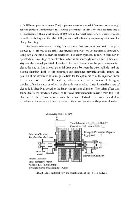
The deceleration system in Fig. 2-8 is a simplified version of that used in the pilot<br />
breeder [2-7]. Instead of the multi-step deceleration, two-step deceleration is adopted by<br />
using two concentric cylindrical electrodes. The outer cylinder, 40 mm in diameter, is<br />
operated as a final stage of deceleration, whereas the inner cylinder, 20 mm in diameter,<br />
stays on the ground potential. Therefore, the main deceleration happens between two<br />
electrodes and further smooth potential drop exists between the outer cylinder and the<br />
plasma chamber. Both of the electrodes are altogether movable axially around the<br />
position of the maximum axial magnetic field for the optimization of the injection under<br />
the influence of the field. The outer cylinder is now removed because of the aging<br />
problem of the insulator on which the electrode was attached. Instead, a similar shape of<br />
electrode is directly attached to the inner tube (plasma chamber). The aging effect was<br />
found due to the irradiation effect of RF wave unintentionally leaking from the ECR<br />
chamber. In the present system, only the ground electrode (i.e. inner cylinder) is<br />
movable and the outer electrode is always on the same potential as the plasma chamber.<br />
Fig. 2-8. Cross-sectional view and specifications of the 18-GHz <strong>KEK</strong>CB<br />
11