TRIAC Progress Report - KEK
TRIAC Progress Report - KEK
TRIAC Progress Report - KEK

You also want an ePaper? Increase the reach of your titles
YUMPU automatically turns print PDFs into web optimized ePapers that Google loves.
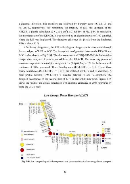
a diagonal direction. The monitors are followed by Faraday cups, FC-LBT01 and<br />
FC-LBT02, respectively. For monitoring the intensity of RIB just upstream of the<br />
<strong>KEK</strong>CB, a plastic scintillator (2 x 2 x 2 cm 3 ), SCI-LBT01 in Fig. 2-34, is installed in<br />
the injection side of the <strong>KEK</strong>CB. It was covered by an aluminum plate of 100-µm thick<br />
where the RIB was implanted. The detection efficiency for β-rays from the implanted<br />
RIBs is about 50 %.<br />
After being charge-bred, the RIB with a higher charge state is transported through<br />
the second part of LBT to ACC. The ion-optical configuration between the <strong>KEK</strong>CB and<br />
ACC is also shown in Fig. 2-34. The first component of 2MQ-MD-2MQ is dedicated to<br />
charge state analysis of ions extracted from the <strong>KEK</strong>CB. The resolving power of<br />
mass-to-charge state ratio (A/q) is designed to be (A/q)/δ(A/q) = 128 for the beams with<br />
emittance of 100π mm•mrad. Three Faraday cups (FC-LBTFi, i = 1, 2, 3) and three<br />
plastic scintillators (SCI-LBTFi, i = 1, 2, 3) are installed at F1, F2 and F3 chambers. A<br />
beam profile monitor, BPM-LBT04, is installed between F1 and F2 chambers. The<br />
designed acceptance of the second part of LBT is also 200π mm•mrad. Figure 2-35<br />
shows the result of ion optical simulation with an initial emittance of 200π mm•mrad by<br />
using the GIOS code.<br />
Fig. 2-34 .Ion transporting optical components and beam monitors for low energy beam transport.<br />
40