TRIAC Progress Report - KEK
TRIAC Progress Report - KEK
TRIAC Progress Report - KEK

You also want an ePaper? Increase the reach of your titles
YUMPU automatically turns print PDFs into web optimized ePapers that Google loves.
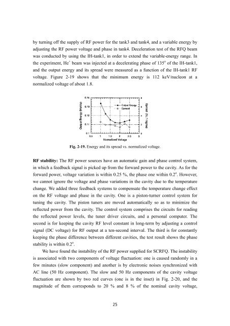
y turning off the supply of RF power for the tank3 and tank4, and a variable energy by<br />
adjusting the RF power voltage and phase in tank4. Deceleration test of the RFQ beam<br />
was conducted by using the IH-tank1, in order to extend the variable-energy range. In<br />
the experiment, He + beam was injected at a decelerating phase of 135 o of the IH-tank1,<br />
and the output energy and its spread were measured as a function of the IH-tank1 RF<br />
voltage. Figure 2-19 shows that the minimum energy is 112 keV/nucleon at a<br />
normalized voltage of about 1.8.<br />
Fig. 2-19. Energy and its spread vs. normalized voltage.<br />
RF stability: The RF power sources have an automatic gain and phase control system,<br />
in which a feedback signal is picked up from the forward power to the cavity. As for the<br />
forward power, voltage variation is within 0.25 %, the phase one within 0.2 o . However,<br />
we cannot ignore the voltage and phase variations in the cavity due to the temperature<br />
change. We added three feedback systems to compensate the temperature change effect<br />
on the RF voltage and phase in the cavity. One is a piston-turner control system for<br />
tuning the cavity. The piston tuners are moved automatically so as to minimize the<br />
reflected power from the cavity. The control system comprises the circuits for reading<br />
the reflected power levels, the tuner driver circuits, and a personal computer. The<br />
second is for keeping the cavity RF level constant in long-term by adjusting a control<br />
signal (DC voltage) for RF output at a ten-second interval. The third is for constantly<br />
keeping the phase difference between different cavities, the test result shows the phase<br />
stability is within 0.2 o .<br />
We have found the instability of the RF power supplied for SCRFQ. The instability<br />
is associated with two components of voltage fluctuation: one is caused randomly in a<br />
few minutes (slow component) and another is by electronic noises synchronized with<br />
AC line (50 Hz component). The slow and 50 Hz components of the cavity voltage<br />
fluctuation are shown by two red curves (one is in the inset) in Fig. 2-20, and the<br />
magnitude of them corresponds to 20 % and 8 % of the nominal cavity voltage,<br />
25