USNO Circular 179 - U.S. Naval Observatory
USNO Circular 179 - U.S. Naval Observatory
USNO Circular 179 - U.S. Naval Observatory
You also want an ePaper? Increase the reach of your titles
YUMPU automatically turns print PDFs into web optimized ePapers that Google loves.
28 CELESTIAL REFERENCE SYSTEM<br />
the precession algorithm assumes a dynamical coordinate system. That is, the above transformation<br />
is a necessary step in obtaining coordinates with respect to the mean equator and equinox of date,<br />
if one starts with ICRS reference data. See Chapter 5 for more information.<br />
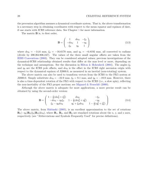
The matrix B is, to first order,<br />
⎛<br />
⎞<br />
B =<br />
⎜<br />
⎝<br />
1 dα0 −ξ0<br />
−dα0 1 −η0<br />
ξ0 η0 1<br />
⎟<br />
⎠ (3.3)<br />
where dα0 = −14.6 mas, ξ0 = −16.6170 mas, and η0 = −6.8192 mas, all converted to radians<br />
(divide by 206 264 806.247). The values of the three small angular offsets are taken from the<br />
IERS Conventions (2003). They can be considered adopted values; previous investigations of the<br />
dynamical-ICRS relationship obtained results that differ at the mas level or more, depending on<br />
the technique and assumptions. See the discussion in Hilton & Hohenkerk (2004). The angles ξ0<br />
and η0 are the ICRS pole offsets, and dα0 is the offset in the ICRS right ascension origin with<br />
respect to the dynamical equinox of J2000.0, as measured in an inertial (non-rotating) system.<br />
The above matrix can also be used to transform vectors from the ICRS to the FK5 system at<br />
J2000.0. Simply substitute dα0 = −22.9 mas, ξ0 = 9.1 mas, and η0 = −19.9 mas. However, there<br />
is also a time-dependent rotation of the FK5 with respect to the ICRS (i.e., a slow spin), reflecting<br />
the non-inertiality of the FK5 proper motions; see Mignard & Frœschlé (2000).<br />
Although the above matrix is adequate for most applications, a more precise result can be<br />
obtained by using the second-order version:<br />
⎛<br />
⎞<br />
B =<br />
⎜<br />
⎝<br />
1 − 1<br />
2 (dα2 0 + ξ2 0 ) dα0 −ξ0<br />
−dα0 − η0ξ0<br />
1 − 1<br />
2 (dα2 0 + η2 0<br />
) −η0<br />
ξ0 − η0dα0 η0 + ξ0dα0 1 − 1<br />
2 (η2 0 + ξ2 0 )<br />
⎟<br />
⎠ (3.4)<br />
The above matrix, from Slabinski (2005), is an excellent approximation to the set of rotations<br />
R1(−η0)R2(ξ0)R3(dα0), where R1, R2, and R3 are standard rotations about the x, y, and z axes,<br />
respectively (see “Abbreviations and Symbols Frequently Used” for precise definitions).


