USNO Circular 179 - U.S. Naval Observatory
USNO Circular 179 - U.S. Naval Observatory
USNO Circular 179 - U.S. Naval Observatory
Create successful ePaper yourself
Turn your PDF publications into a flip-book with our unique Google optimized e-Paper software.
58 MODELING THE EARTH’S ROTATION<br />
right ascension of the object, measured with respect to the true equinox, and λ is the longitude<br />
of the observer (corrected, where necessary, for polar motion). Obviously these quantities must<br />
all be given in the same units. In the CIO-based scheme, the apparent place would be expressed<br />
in the Celestial Intermediate Reference System (Eσ), and h = θ – ασ + λ, where θ is the Earth<br />
Rotation Angle and ασ is the apparent right ascension of the object, measured with respect to the<br />
CIO. (The recommended terminology is intermediate place for the object position in the Eσ and<br />
intermediate right ascension for the quantity ασ, although some people hold that the term right<br />
ascension should refer only to an origin at the equinox.) In the CIO-based formula, precession and<br />
nutation come into play only once, in expressing the object’s right ascension in the Eσ system. See<br />
section 6.5.4 for more details.<br />
6.5 Formulas<br />
The formulas below draw heavily on the developments presented previously. In particular, the<br />
3×3 matrices P, N, and B represent the transformations for precession, nutation, and frame bias,<br />
respectively, and are taken directly from Chapters 5 and 3. The matrices P and N are functions<br />
of time, t. The time measured in Julian centuries of TDB (or TT) from J2000.0 is denoted T and<br />
is given by T = (JD(TDB) – 2451545.0)/36525. The elementary rotation matrices R1, R2, and<br />
R3 are defined in “Abbreviations and Symbols Frequently Used”. Formulas from Chapter 2 for<br />
sidereal time and the Earth Rotation Angle are used. Explanations of, and formulas for the time<br />
scales UT1, TT, and TDB are also found in Chapter 2.<br />
The ultimate objective is to express “local” Earth-fixed vectors, representing geographic positions,<br />
baselines, instrumental axes and boresights, etc., in the GCRS, where they can be related to<br />
the proper coordinates 5 of celestial objects. As mentioned above, the “GCRS” is a reference system<br />
that can be thought of as the “geocentric ICRS”. Celestial coordinates in the GCRS are obtained<br />
from basic ICRS data (which are barycentric) by applying the usual algorithms for proper place;<br />
see section 1.3. In this chapter we will be working entirely in a geocentric system and the GCRS<br />
will be obtained from a series of rotations that start with an ordinary Earth-fixed geodetic system.<br />
6.5.1 Location of Cardinal Points<br />
We will start by establishing the positions of three cardinal points within the GCRS: the Celestial<br />
Intermediate Pole (CIP), the true equinox of date (Υ), and the Celestial Intermediate Origin (CIO).<br />
The unit vectors toward these points will be designated n GCRS , Υ GCRS , and σ GCRS , respectively. As<br />
the Earth precesses and nutates in local inertial space, these points are in continual motion.<br />
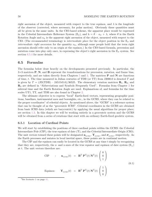
The CIP and the equinox can easily be located in the GCRS at any time t simply by recognizing<br />
that they are, respectively, the z- and x-axes of the true equator and equinox of date system (E Υ )<br />
at t. The unit vectors therefore are:<br />
5 See footnote 1 on page 41.<br />
CIP : n GCRS (t) = B T P T (t) N T (t)<br />
Equinox: Υ GCRS (t) = B T P T (t) N T (t)<br />
⎛<br />
⎜<br />
⎝<br />
⎛<br />
⎜<br />
⎝<br />
0<br />
0<br />
1<br />
1<br />
0<br />
0<br />
⎞<br />
⎟<br />
⎠<br />
⎞<br />
⎟<br />
⎠<br />
(6.1)


