iter structural design criteria for in-vessel components (sdc-ic)
iter structural design criteria for in-vessel components (sdc-ic)
iter structural design criteria for in-vessel components (sdc-ic)
You also want an ePaper? Increase the reach of your titles
YUMPU automatically turns print PDFs into web optimized ePapers that Google loves.
ITER G 74 MA 8 01-05-28 W0.2<br />
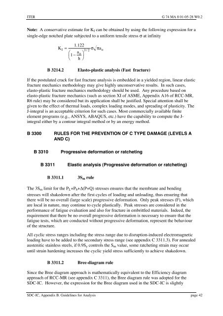
Note: A conservative estimate <strong>for</strong> KI can be obta<strong>in</strong>ed by us<strong>in</strong>g the follow<strong>in</strong>g expression <strong>for</strong> a<br />
s<strong>in</strong>gle-edge notched plate subjected to a uni<strong>for</strong>m tensile stress s at <strong>in</strong>f<strong>in</strong>ity<br />
K<br />
I<br />
1. 122<br />
=<br />
æ ao<br />
1 -<br />
ö<br />
è h ø<br />
3/ 2 s p<br />
a<br />
B 3214.2 Elasto-plast<strong>ic</strong> analysis (Fast fracture)<br />
o<br />
If the postulated crack <strong>for</strong> fast fracture analysis is embedded <strong>in</strong> a yielded region, l<strong>in</strong>ear elast<strong>ic</strong><br />
fracture mechan<strong>ic</strong>s methodology may give highly unconservative results. In such cases,<br />
elasto-plast<strong>ic</strong> fracture mechan<strong>ic</strong>s methodology should be used. Any procedure based on<br />
elasto-plast<strong>ic</strong> fracture mechan<strong>ic</strong>s (such as section XI of ASME, Appendix A16 of RCC-MR,<br />
R6 rule) may be considered but its appl<strong>ic</strong>ation shall be justified. Special attention shall be<br />
given to the effect of thermal loads, complex load<strong>in</strong>g modes, and spread<strong>in</strong>g of plast<strong>ic</strong>ity. The<br />
J-<strong>in</strong>tegral is an acceptable cr<strong>iter</strong>ion <strong>for</strong> such cases. Most commercially available f<strong>in</strong>ite<br />
element programs (e.g., ANSYS, ABAQUS, etc.) have the capability to compute the J<strong>in</strong>tegral<br />
either by a contour <strong>in</strong>tegral method or by an energy method.<br />
B 3300 RULES FOR THE PREVENTION OF C TYPE DAMAGE (LEVELS A<br />
AND C)<br />
B 3310 Progressive de<strong>for</strong>mation or ratchet<strong>in</strong>g<br />
B 3311 Elast<strong>ic</strong> analysis (Progressive de<strong>for</strong>mation or ratchet<strong>in</strong>g)<br />
B 3311.1 3Sm rule<br />
The 3Sm limit <strong>for</strong> the PL+Pb+D(P+Q) stresses ensures that the membrane and bend<strong>in</strong>g<br />
stresses will shakedown after the first cycles of load<strong>in</strong>g and unload<strong>in</strong>g, thus ensur<strong>in</strong>g that<br />
there will be no overall (large scale) progressive de<strong>for</strong>mation. Only peak stresses (F), wh<strong>ic</strong>h<br />
are local <strong>in</strong> nature, may cont<strong>in</strong>ue to cycle plast<strong>ic</strong>ally. Peak stresses are considered <strong>in</strong> the<br />
per<strong>for</strong>mance of fatigue evaluation and also <strong>for</strong> fracture <strong>in</strong> embrittled materials. Indeed, the<br />
requirement that there be no overall progressive de<strong>for</strong>mation is necessary to ensure that the<br />
fatigue tests, wh<strong>ic</strong>h are conducted without progressive de<strong>for</strong>mation, represent the behaviour<br />
of the structure.<br />
All cycl<strong>ic</strong> stress ranges <strong>in</strong>clud<strong>in</strong>g the stress range due to disruption-<strong>in</strong>duced electromagnet<strong>ic</strong><br />
load<strong>in</strong>g have to be added to the secondary stress range (see appendix C 3311.3). For annealed<br />
austenit<strong>ic</strong> sta<strong>in</strong>less steels, if 0.9Sy controls the Sm value, some ratchet<strong>in</strong>g stra<strong>in</strong> may occur<br />
until stra<strong>in</strong> harden<strong>in</strong>g <strong>in</strong>creases the cycl<strong>ic</strong> yield stress suff<strong>ic</strong>iently to achieve shakedown.<br />
B 3311.2 Bree-diagram rule<br />
S<strong>in</strong>ce the Bree diagram approach is mathemat<strong>ic</strong>ally equivalent to the Eff<strong>ic</strong>iency diagram<br />
approach of RCC-MR (see appendix C 3311), the Bree diagram rule was adopted <strong>for</strong> the<br />
SDC-IC. However, the expression <strong>for</strong> the Bree diagram used <strong>in</strong> the SDC-IC is slightly<br />
SDC-IC, Appendix B. Guidel<strong>in</strong>es <strong>for</strong> Analysis page 42


