iter structural design criteria for in-vessel components (sdc-ic)
iter structural design criteria for in-vessel components (sdc-ic)
iter structural design criteria for in-vessel components (sdc-ic)

Create successful ePaper yourself
Turn your PDF publications into a flip-book with our unique Google optimized e-Paper software.
ITER G 74 MA 8 01-05-28 W0.2<br />
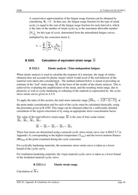
A conservative approximation of the fatigue usage fraction can be obta<strong>in</strong>ed by<br />
consider<strong>in</strong>g Fe = 0 . In that case, the fatigue usage fraction <strong>for</strong> the type of stra<strong>in</strong><br />
cycle j is equal to the sum of the fatigue usage fraction <strong>for</strong> each <strong>in</strong>terval k, wh<strong>ic</strong>h<br />
is the ratio of the number of stra<strong>in</strong> cycles nk to the maximum allowable number<br />
( N j ) <strong>for</strong> this type of cycle, determ<strong>in</strong>ed from the unirradiated fatigue curves,<br />
k<br />
multiplied by the correction factor f k:<br />
N é M j<br />
V = å êå<br />
f<br />
j=<br />
1 ê<br />
ëk<br />
= 1<br />
k<br />
n<br />
N<br />
k<br />
( )<br />
j k<br />
B 3323. Calculation of equivalent stra<strong>in</strong> range De<br />
ù<br />
ú<br />
ú<br />
û<br />
B 3323.1 Elast<strong>ic</strong> analysis (Time-<strong>in</strong>dependent fatigue)<br />
When elast<strong>ic</strong> analysis is used to calculate the response of a structure, the range of stra<strong>in</strong>s<br />
obta<strong>in</strong>ed does not account <strong>for</strong> plast<strong>ic</strong> stra<strong>in</strong>s wh<strong>ic</strong>h would occur if the real behavior of the<br />
material were taken <strong>in</strong>to consideration . The method outl<strong>in</strong>ed below is aimed at provid<strong>in</strong>g an<br />
estimate of the "real" stra<strong>in</strong> range De on the basis of the results of the elast<strong>ic</strong> analysis. This is<br />
achieved by evaluat<strong>in</strong>g the amplif<strong>ic</strong>ation of the stra<strong>in</strong>, and the result<strong>in</strong>g stra<strong>in</strong> range, due to<br />
plast<strong>ic</strong>ity as well as cycl<strong>ic</strong> harden<strong>in</strong>g or soften<strong>in</strong>g of the material as represented by the cycl<strong>ic</strong><br />
stress-stra<strong>in</strong> curves given <strong>in</strong> A.5.9.<br />
( ( ) ) at<br />
To apply the rules of this section, the total stress <strong>in</strong>tensity range Dstot = D P + Q + F<br />
the po<strong>in</strong>t under consideration and <strong>for</strong> each of the cycles must be calculated elast<strong>ic</strong>ally, us<strong>in</strong>g<br />
the procedure given <strong>in</strong> B 2550. This range can be obta<strong>in</strong>ed either by a suff<strong>ic</strong>iently detailed<br />
calculation of the region concerned or by us<strong>in</strong>g an appropriate stress concentration factor.<br />
The value of the total effective stra<strong>in</strong> range De is the sum of four scalar stra<strong>in</strong>s<br />
De , De , De , De<br />
:<br />
1 2 3 4<br />
De = De + De + De + De<br />
1 2 3 4<br />
These four terms are determ<strong>in</strong>ed us<strong>in</strong>g a uniaxial cycl<strong>ic</strong> stress-stra<strong>in</strong> curve (see A.MAT.5.7 <strong>in</strong><br />
Appendix A) correspond<strong>in</strong>g to the highest temperature (Tmax) and the lowest neutron fluence<br />
(Ft)m<strong>in</strong> at the po<strong>in</strong>t exam<strong>in</strong>ed dur<strong>in</strong>g the cycle concerned.<br />
For cycl<strong>ic</strong>ally harden<strong>in</strong>g materials, the monoton<strong>ic</strong> stress-stra<strong>in</strong> curve is taken as a lower<br />
bound of the cycl<strong>ic</strong> curve.<br />
For irradiation harden<strong>in</strong>g materials, the virg<strong>in</strong> material cycl<strong>ic</strong> curve is taken as a lower bound<br />
of the irradiated material cycl<strong>ic</strong> curve.<br />
Calculation of De 1:<br />
B 3323.1.1 Elast<strong>ic</strong> stra<strong>in</strong> range<br />
SDC-IC, Appendix B. Guidel<strong>in</strong>es <strong>for</strong> Analysis page 46