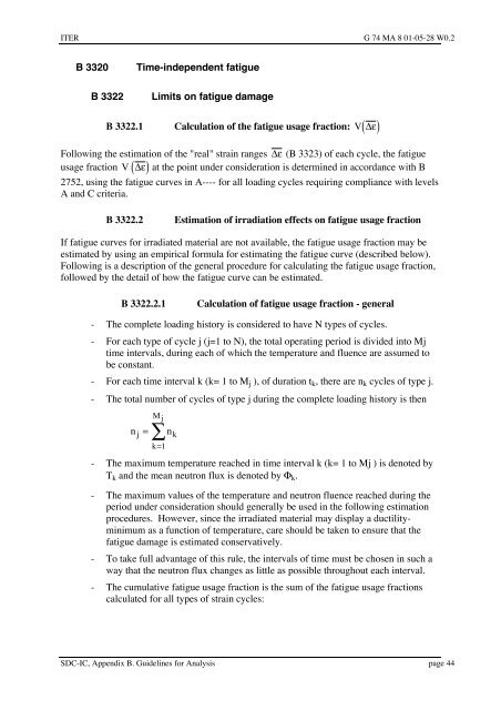
iter structural design criteria for in-vessel components (sdc-ic)
iter structural design criteria for in-vessel components (sdc-ic)
iter structural design criteria for in-vessel components (sdc-ic)
You also want an ePaper? Increase the reach of your titles
YUMPU automatically turns print PDFs into web optimized ePapers that Google loves.
ITER G 74 MA 8 01-05-28 W0.2<br />
B 3320 Time-<strong>in</strong>dependent fatigue<br />
B 3322 Limits on fatigue damage<br />
B 3322.1 Calculation of the fatigue usage fraction: V( De)<br />
Follow<strong>in</strong>g the estimation of the "real" stra<strong>in</strong> ranges De (B 3323) of each cycle, the fatigue<br />
usage fraction V ( De)<br />
at the po<strong>in</strong>t under consideration is determ<strong>in</strong>ed <strong>in</strong> accordance with B<br />
2752, us<strong>in</strong>g the fatigue curves <strong>in</strong> A---- <strong>for</strong> all load<strong>in</strong>g cycles requir<strong>in</strong>g compliance with levels<br />
A and C cr<strong>iter</strong>ia.<br />
B 3322.2 Estimation of irradiation effects on fatigue usage fraction<br />
If fatigue curves <strong>for</strong> irradiated material are not available, the fatigue usage fraction may be<br />
estimated by us<strong>in</strong>g an empir<strong>ic</strong>al <strong>for</strong>mula <strong>for</strong> estimat<strong>in</strong>g the fatigue curve (described below).<br />
Follow<strong>in</strong>g is a description of the general procedure <strong>for</strong> calculat<strong>in</strong>g the fatigue usage fraction,<br />
followed by the detail of how the fatigue curve can be estimated.<br />
BÊ3322.2.1 Calculation of fatigue usage fraction - general<br />
- The complete load<strong>in</strong>g history is considered to have N types of cycles.<br />
- For each type of cycle j (j=1 to N), the total operat<strong>in</strong>g period is divided <strong>in</strong>to Mj<br />
time <strong>in</strong>tervals, dur<strong>in</strong>g each of wh<strong>ic</strong>h the temperature and fluence are assumed to<br />
be constant.<br />
- For each time <strong>in</strong>terval k (k= 1 to Mj ), of duration tk, there are nk cycles of type j.<br />
- The total number of cycles of type j dur<strong>in</strong>g the complete load<strong>in</strong>g history is then<br />
M j<br />
å 1<br />
n = n<br />
j k<br />
k =<br />
- The maximum temperature reached <strong>in</strong> time <strong>in</strong>terval k (k= 1 to Mj ) is denoted by<br />
Tk and the mean neutron flux is denoted by Fk.<br />
- The maximum values of the temperature and neutron fluence reached dur<strong>in</strong>g the<br />
period under consideration should generally be used <strong>in</strong> the follow<strong>in</strong>g estimation<br />
procedures. However, s<strong>in</strong>ce the irradiated material may display a ductilitym<strong>in</strong>imum<br />
as a function of temperature, care should be taken to ensure that the<br />
fatigue damage is estimated conservatively.<br />
- To take full advantage of this rule, the <strong>in</strong>tervals of time must be chosen <strong>in</strong> such a<br />
way that the neutron flux changes as little as possible throughout each <strong>in</strong>terval.<br />
- The cumulative fatigue usage fraction is the sum of the fatigue usage fractions<br />
calculated <strong>for</strong> all types of stra<strong>in</strong> cycles:<br />
SDC-IC, Appendix B. Guidel<strong>in</strong>es <strong>for</strong> Analysis page 44


