iter structural design criteria for in-vessel components (sdc-ic)
iter structural design criteria for in-vessel components (sdc-ic)
iter structural design criteria for in-vessel components (sdc-ic)

You also want an ePaper? Increase the reach of your titles
YUMPU automatically turns print PDFs into web optimized ePapers that Google loves.
ITER G 74 MA 8 01-05-28 W0.2<br />
and a l<strong>in</strong>e <strong>in</strong>tegration through the th<strong>ic</strong>kness is used to calculate the breakdown of stresses at<br />
any position. On the other hand, if the tube is analysed as a beam, then the membrane and<br />
bend<strong>in</strong>g stress apply to the cross-section as a whole, and an area <strong>in</strong>tegral over the total crosssectional<br />
area of the tube would be more appropriate.<br />
Once a determ<strong>in</strong>ation has been made as to wh<strong>ic</strong>h type of <strong>in</strong>tegration (l<strong>in</strong>e <strong>in</strong>tegral or area<br />
<strong>in</strong>tegral) is more appropriate, a membrane stress component can be def<strong>in</strong>ed as the average or<br />
mean value of that stress component along that l<strong>in</strong>e or area. The bend<strong>in</strong>g component of the<br />
stress is a l<strong>in</strong>early vary<strong>in</strong>g stress wh<strong>ic</strong>h can be def<strong>in</strong>ed <strong>in</strong> such a way that its moment about<br />
the centroid of the l<strong>in</strong>e segment or the area is the same as the moment of the total stress<br />
component m<strong>in</strong>us the membrane stress component about the centroid.<br />
BÊ2513 Membrane stress<br />
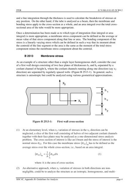
As an example of a structure other than a s<strong>in</strong>gle layer homogeneous shell, consider the case<br />
of a first wall <strong>design</strong> consist<strong>in</strong>g of two face plates of th<strong>ic</strong>knesses h1 and h2 separated by a<br />
coolant channel of height hc where the coolant channels runn<strong>in</strong>g along one direction (say x2<br />
direction) are separated by regularly spaced webs á(Figure B 2513-1). In general, such a<br />
structure is anisotrop<strong>ic</strong> but could be analyzed us<strong>in</strong>g various geometr<strong>ic</strong>al approximations.<br />
X 3<br />
SDC-IC, Appendix B. Guidel<strong>in</strong>es <strong>for</strong> Analysis page 4<br />
X 1<br />
Figure BÊ2513-1: First wall cross-section<br />
(1) At an elementary level, when x3 variation of stresses <strong>in</strong> the x1 direction can be<br />
neglected, a sl<strong>ic</strong>e of the first wall consist<strong>in</strong>g of halves of two adjacent coolant channels<br />
together with their face plates may be analyzed as a one-dimensional stress analysis<br />
problem. The cross-section of <strong>in</strong>terest is like an I-beam and the stress of <strong>in</strong>terest is the<br />
normal stress s22. For this case the membrane stress ( s22 ) has to be def<strong>in</strong>ed as the<br />
m<br />
average stress over the whole cross-section, i.e., based on an area <strong>in</strong>tegral.<br />
1<br />
( s ) = ò s<br />
m A<br />
22 22<br />
A<br />
dA (1)<br />
where A is the area of cross-section.<br />
(2) An alternative approach, when x3 variation of stresses <strong>in</strong> both directions are nonnegligible,<br />
could be to analyze the structure as an isotrop<strong>ic</strong>, homogeneous, and multi-<br />
h 1<br />
h c<br />
h 2