constant/current chopper drive ups stepper/motor ... - Fribotte
constant/current chopper drive ups stepper/motor ... - Fribotte
constant/current chopper drive ups stepper/motor ... - Fribotte

You also want an ePaper? Increase the reach of your titles
YUMPU automatically turns print PDFs into web optimized ePapers that Google loves.
PULSE WIDTH-MODULATED DRIVE IM-<br />
PROVES MOTOR TORQUE AND SPEED<br />
YET ADDS NO COMPLEXITY TO CIRCUIT<br />
Designers opting to use a fractional-horsepower<br />
<strong>stepper</strong> <strong>motor</strong> in applications such as computer<br />
printers can improve the <strong>motor</strong>’s efficiency and its<br />
torque and speed characteristics by using a <strong>constant</strong>-<strong>current</strong><br />
pulse-width-modulated (PWM) <strong>chopper</strong>-<strong>drive</strong><br />
circuit. What’s more, for high-power<br />
<strong>drive</strong>s, dedicated control chips and a <strong>constant</strong>-<strong>current</strong><br />
<strong>chopper</strong><strong>drive</strong> can be as simple to use as direct<br />
<strong>drive</strong>.<br />
A basic problem for a directly <strong>drive</strong>n <strong>stepper</strong> is that<br />
the <strong>motor</strong> winding’s time <strong>constant</strong> (L/R) causes the<br />
<strong>current</strong> to increase slowly in the winding during each<br />
pulsedinput. Itmay, therefore,neverreach full-rated<br />
value, especially at high speed, or high pulsing rates,<br />
unless the voltage (VS) across the terminals is<br />
AN468/0392<br />
APPLICATION NOTE<br />
CONSTANT-CURRENT CHOPPER DRIVE UPS<br />
STEPPER-MOTOR PERFORMANCE<br />
The most efficient and performant way to <strong>drive</strong> a <strong>stepper</strong> <strong>motor</strong> is to use a ”<strong>chopper</strong>” <strong>drive</strong> circuit.<br />
This note explains some basic theory then presents practical circuits based on power ICs.<br />
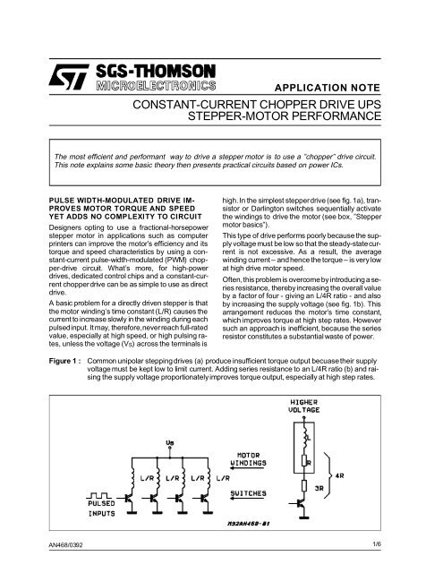
high.In the simplest <strong>stepper</strong><strong>drive</strong> (see fig. 1a), transistor<br />
or Darlington switches sequentially activate<br />
the windings to <strong>drive</strong> the <strong>motor</strong> (see box, ”Stepper<br />
<strong>motor</strong> basics”).<br />
This type of <strong>drive</strong> performs poorly because the supply<br />
voltage must be low so that the steady-state<strong>current</strong><br />
is not excessive. As a result, the average<br />
winding <strong>current</strong> – and hence the torque – is very low<br />
at high <strong>drive</strong> <strong>motor</strong> speed.<br />
Often,this problem is overcomeby introducing a series<br />
resistance, therebyincreasing the overall value<br />
by a factor of four - giving an L/4R ratio - and also<br />
by increasing the supply voltage (see fig. 1b). This<br />
arrangement reduces the <strong>motor</strong>’s time <strong>constant</strong>,<br />
which improves torque at high step rates. However<br />
such an approach is inefficient, because the series<br />
resistor constitutes a substantial waste of power.<br />
Figure 1 : Common unipolar stepping <strong>drive</strong>s (a) produce insufficient torque output becuasetheir supply<br />
voltage must be kept low to limit <strong>current</strong>. Adding series resistance to an L/4R ratio (b) and raising<br />
the supply voltage proportionatelyimproves torque output, especially at high step rates.<br />
1/6
APPLICATION NOTE<br />
Figure 2 : A Pulse-width-modulated, or <strong>chopper</strong>,<br />
<strong>drive</strong> overcomes most of the problems<br />
of the simpler direct <strong>drive</strong> or<br />
even linear <strong>constant</strong>-<strong>current</strong><strong>drive</strong>s.<br />
CONSTANT CURRENT IS BEST<br />
Introducing a feedback loop to control the winding<br />
<strong>current</strong> is a better solution. Linear <strong>constant</strong>-<strong>current</strong><br />
control is possiblebut is rarely used becauseof high<br />
power losses in the power stage. However, a pulsewidth-modulation<br />
scheme – a <strong>chopper</strong> circuit – not<br />
only solves the L/R time-<strong>constant</strong> problem but cuts<br />
power dissipation too (see fig. 2).<br />
A four-phase bifilar/hybrid unipolar <strong>stepper</strong> <strong>motor</strong><br />
could use a quad Darlington like the ULN2075B as<br />
a <strong>chopper</strong><strong>drive</strong>r and a chip like the L6506 as a <strong>current</strong><br />
controller (see fig. 3).<br />
The L6506, which contains all the <strong>chopper</strong>circuitry,<br />
is simple to use. An external RC network sets the<br />
oscillator frequency, and a voltage divider (or trimmer)<br />
sets the reference voltages, and hence the<br />
phase <strong>current</strong>s. Normally an oscillator frequency of<br />
over 20 KHz is chosen to avoid <strong>motor</strong> noise. The<br />
maximum usable frequency depends on the L/R<br />
time <strong>constant</strong> of the <strong>motor</strong>.<br />
Controlsignals for the four-phaseinputs can be provided<br />
by a micro-computer chip or a simple repetitive<br />
sequencefrom a logic circuit. Note thattheL6506<br />
contains just two independent <strong>chopper</strong>-control loops<br />
- sufficient for a four-phase unipolar stepping<br />
<strong>motor</strong> because opposing windings never energize<br />
together.<br />
DRIVING BIPOLAR MOTORS<br />
Bipolar <strong>stepper</strong> <strong>motor</strong>s, preferred for their better<br />
torque/weightratio, however, are normally <strong>drive</strong>n by<br />
H-bridge output stages. They enable a single-polarity<br />
supply to <strong>drive</strong> each <strong>motor</strong> winding end sequentially<br />
to achieve a polarity-reversal effect on the<br />
windings.<br />
Figure 3 : A simple <strong>chopper</strong> <strong>drive</strong> for a unipolar stepping <strong>motor</strong>, can be assembled with just two chips :<br />
a Quad Darlington output <strong>drive</strong>r IC and <strong>constant</strong>-<strong>current</strong> feedback controller IC.<br />
2/6
STEPPER-MOTOR BASICS<br />
In computer-peripheral office-equipment applications,<br />
the most popular <strong>stepper</strong> <strong>motor</strong>s are permanent-magnet<br />
types with two-phase bipolar windings<br />
or bifilar-wound unipolar windings. Stripped to the<br />
essentials, both types consist of a permanent-magnet<br />
rotor surrounded by stator poles carrying the<br />
windings.<br />
A two-pole <strong>motor</strong> would have a step angle of 90 °.<br />
However, most <strong>motor</strong>s have multiple poles to reduce<br />
the step angle to a few degrees.<br />
A bipolar permanent-magnet <strong>stepper</strong> <strong>motor</strong> has a<br />
single winding for each phase – and the <strong>current</strong><br />
must be reversed to reverse the stator field. Bifilar/hybrid<br />
unipolar <strong>motor</strong>s, however, have two windings<br />
wound in opposite directions for each phase,<br />
so that the field can be reversed with a single-polarity<br />
<strong>drive</strong>. Unipolar <strong>motor</strong>s were once popular because<br />
the <strong>drive</strong> was simpler. But with today’s dual<br />
bridge (H-bridge) ICs, it is just as easy to <strong>drive</strong> a bipolar<br />
<strong>motor</strong>.<br />
In the most popular <strong>drive</strong> technique - two-phase-on<br />
- both phases are always energized. In anothermethod<br />
– called the wave <strong>drive</strong> – one phase is energized<br />
at a time.<br />
APPLICATION NOTE<br />
A third technique combines the two sequences and<br />
<strong>drive</strong>s the <strong>motor</strong> one half-step at a time. Half-stepping<br />
is very useful because<strong>motor</strong> mechanically designed<br />
for very small step angles are much more<br />
complex –and costly– to built. Itis moreeconomical<br />
to use a 100-step <strong>motor</strong> in half steps rather than a<br />
200-step <strong>motor</strong> in full step.<br />
Recently designers have started microstepping, or<br />
driving the <strong>motor</strong> at one-quarter stepping rather or<br />
less. This type of operationcanobtain fine step control<br />
without usingmechanically complex <strong>motor</strong>s with<br />
small step angles.<br />
A two-phase bipolar <strong>motor</strong> needing up to 2A/phase<br />
can be <strong>drive</strong>n by a single IC - the L298N dual<br />
bridge (see fig. 4). It contains two H-bridges with all<br />
the necessary level shifters and gates to directly interface<br />
low-level input logic signals.<br />
As before, a complete <strong>chopper</strong> <strong>drive</strong> can be built by<br />
adding a <strong>current</strong>-controller chip and the necessary<br />
protectivediodes, an RCnetworkto define the oscillator<br />
frequency and a reference-voltage divider to<br />
set the <strong>current</strong> level. Four-phasesignals to the controller<br />
are provided by a controlling microcomputer<br />
or by another dedicated controller chip - the L297<br />
<strong>stepper</strong>-<strong>motor</strong> controller.<br />
Figure 4 : A Dual-bridge IC provides a simple power-stage design solution for a bipolar <strong>stepper</strong> <strong>motor</strong>.<br />
3/6
APPLICATION NOTE<br />
Containingan internaltranslator circuit controlled by<br />
step-and-directioninputs, the L297 <strong>motor</strong> controller<br />
(see fig. 5) allows operation in three modes : twophase-on,<br />
half-step and wave-<strong>drive</strong>.<br />
The normal two-phase-onmode is selected by a low<br />
level on the half/full input when the device has been<br />
reset to start.<br />
Half-step <strong>drive</strong> is selected by a high level on the<br />
half/fullstep input.To initialize the wave-<strong>drive</strong> mode,<br />
the user disables the output stage (brings enable<br />
low), resets the device, steps the translator one<br />
step, bringshalf/full low, andthen reenablestheoutputs.<br />
The L297 also lets the designer select either phase<br />
or inhibit chopping. Phase chopping provides lower<br />
ripple and is suitable four unipolar <strong>motor</strong>, whereas<br />
inhibit chopping returns energy to the supply and is<br />
better for bipolar <strong>motor</strong>s.<br />
In applicationssuch as printer-paperfeed, the<strong>motor</strong><br />
is often at rest. Sincethe full torque isnot usuallynecessary<br />
to hold the <strong>motor</strong> in position, designerscan<br />
save power by switching the <strong>current</strong> to a lower level<br />
between runs. With an L297 or L6506 control chip,<br />
this task can be done by simply switching the reference<br />
input between two levels.<br />
Where several <strong>chopper</strong><strong>drive</strong>s are used in the same<br />
system, they should be synchronized prevent intermodulation<br />
effects. This is done by connecting the<br />
sync pins to one another and omitting the oscillator<br />
RC network on all but one device.<br />
Figure 5 : controlled by step, direction, and mode inputs, the L297 <strong>stepper</strong>-<strong>motor</strong> controller chip performs<br />
some of the functions of a controlling microcomputer.<br />
4/6
HANDLING HIGH CURRENT<br />
For <strong>current</strong> <strong>drive</strong>s greater than 2A/phase, the two<br />
bridgesin an L298N IC can be paralleled by connecting<br />
inputs to the corresponding outputs. However,<br />
for a more equal distribution of the load and chip<br />
heating, <strong>drive</strong>r 1 should be paralleled with <strong>drive</strong>r 4,<br />
and <strong>drive</strong>r 2 with <strong>drive</strong>r 3. Additionally, total <strong>current</strong><br />
shouldbe deratedby 0.5 Ato allow for the maximum<br />
possible imbalance between the <strong>current</strong> in each<br />
bridge.Thus twoL298scan <strong>drive</strong> <strong>motor</strong>sratedat 3.5<br />
A/phase.<br />
A different configuration for microstepping <strong>stepper</strong><br />
<strong>motor</strong>s is employed in the PBL3717Acontrol circuit.<br />
It contains all of the control and power circuitry for<br />
APPLICATION NOTE<br />
one phase of a <strong>motor</strong>. An H-bridge outputstage can<br />
<strong>drive</strong> <strong>motor</strong>s rated at up to 1A/phase. Two of these<br />
devicesareneededto <strong>drive</strong> a two-phasebipolar <strong>motor</strong>.<br />
The output <strong>current</strong> level from the PBL3717Ais set<br />
both by an analog-reference input and two logic inputs<br />
(I1 and I0), which select one of three preset <strong>current</strong><br />
levels (the fourth combination disables the<br />
outputs stage). This feature implements the microstepping,in<br />
which several <strong>current</strong> levels are used to<br />
obtain very small step angles for even more precise<br />
control (but at theexpenseof a less regular torque).<br />
Unlike the L297 and L6506, the PBL3717A has a<br />
<strong>constant</strong> off-time <strong>chopper</strong> <strong>drive</strong>r which is ideal for<br />
microstepping.<br />
5/6
APPLICATION NOTE<br />
Information furnished is believed to be accurate and reliable. However, SGS-THOMSON Microelectronics assumes no responsibility for<br />
the consequences of use of such information nor for any infringement of patents or other rights of third parties which may result from its<br />
use. No license is granted by implication or otherwise under any patent or patent rights of SGS-THOMSON Microelectronics. Specifications<br />
mentioned in this publication are subject to change without notice. This publication supersedes and replaces all information previously<br />
supplied. SGS-THOMSON Microelectronics products are not authorized for use as critical components in life support devices or<br />
systems without express written approval of SGS-THOMSON Microelectronics.<br />
© 1995 SGS-THOMSON Microelectronics - All Rights Reserved<br />
SGS-THOMSON Microelectronics GROUP OF COMPANIES<br />
Australia - Brazil - France - Germany - Hong Kong - Italy - Japan - Korea - Malaysia - Malta - Morocco - The Netherlands - Singapore -<br />
Spain - Sweden - Switzerland - Taiwan - Thaliand - United Kingdom - U.S.A.<br />
6/6