The University of Evansville LTSpice IV Component Library
The University of Evansville LTSpice IV Component Library
The University of Evansville LTSpice IV Component Library

Create successful ePaper yourself
Turn your PDF publications into a flip-book with our unique Google optimized e-Paper software.
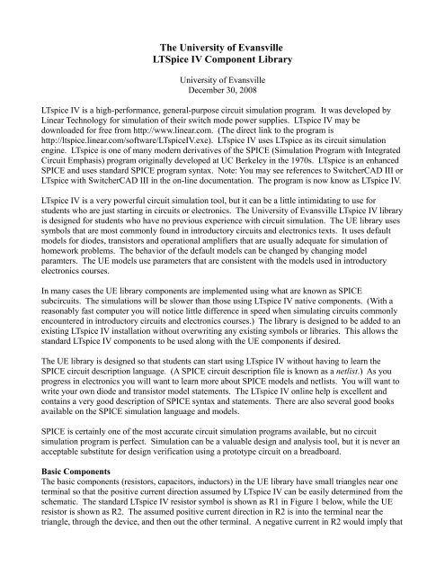
<strong>The</strong> <strong>University</strong> <strong>of</strong> <strong>Evansville</strong><br />
<strong>LTSpice</strong> <strong>IV</strong> <strong>Component</strong> <strong>Library</strong><br />
<strong>University</strong> <strong>of</strong> <strong>Evansville</strong><br />
December 30, 2008<br />
LTspice <strong>IV</strong> is a high-performance, general-purpose circuit simulation program. It was developed by<br />
Linear Technology for simulation <strong>of</strong> their switch mode power supplies. LTspice <strong>IV</strong> may be<br />
downloaded for free from http://www.linear.com. (<strong>The</strong> direct link to the program is<br />
http://ltspice.linear.com/s<strong>of</strong>tware/LTspice<strong>IV</strong>.exe). LTspice <strong>IV</strong> uses LTspice as its circuit simulation<br />
engine. LTspice is one <strong>of</strong> many modern derivatives <strong>of</strong> the SPICE (Simulation Program with Integrated<br />
Circuit Emphasis) program originally developed at UC Berkeley in the 1970s. LTspice is an enhanced<br />
SPICE and uses standard SPICE program syntax. Note: You may see references to SwitcherCAD III or<br />
LTspice with SwitcherCAD III in the on-line documentation. <strong>The</strong> program is now know as LTspice <strong>IV</strong>.<br />
LTspice <strong>IV</strong> is a very powerful circuit simulation tool, but it can be a little intimidating to use for<br />
students who are just starting in circuits or electronics. <strong>The</strong> <strong>University</strong> <strong>of</strong> <strong>Evansville</strong> LTspice <strong>IV</strong> library<br />
is designed for students who have no previous experience with circuit simulation. <strong>The</strong> UE library uses<br />
symbols that are most commonly found in introductory circuits and electronics texts. It uses default<br />
models for diodes, transistors and operational amplifiers that are usually adequate for simulation <strong>of</strong><br />
homework problems. <strong>The</strong> behavior <strong>of</strong> the default models can be changed by changing model<br />
paramters. <strong>The</strong> UE models use parameters that are consistent with the models used in introductory<br />
electronics courses.<br />
In many cases the UE library components are implemented using what are known as SPICE<br />
subcircuits. <strong>The</strong> simulations will be slower than those using LTspice <strong>IV</strong> native components. (With a<br />
reasonably fast computer you will notice little difference in speed when simulating circuits commonly<br />
encountered in introductory circuits and electronics courses.) <strong>The</strong> library is designed to be added to an<br />
existing LTspice <strong>IV</strong> installation without overwriting any existing symbols or libraries. This allows the<br />
standard LTspice <strong>IV</strong> components to be used along with the UE components if desired.<br />
<strong>The</strong> UE library is designed so that students can start using LTspice <strong>IV</strong> without having to learn the<br />
SPICE circuit description language. (A SPICE circuit description file is known as a netlist.) As you<br />
progress in electronics you will want to learn more about SPICE models and netlists. You will want to<br />
write your own diode and transistor model statements. <strong>The</strong> LTspice <strong>IV</strong> online help is excellent and<br />
contains a very good description <strong>of</strong> SPICE syntax and statements. <strong>The</strong>re are also several good books<br />
available on the SPICE simulation language and models.<br />
SPICE is certainly one <strong>of</strong> the most accurate circuit simulation programs available, but no circuit<br />
simulation program is perfect. Simulation can be a valuable design and analysis tool, but it is never an<br />
acceptable substitute for design verification using a prototype circuit on a breadboard.<br />
Basic <strong>Component</strong>s<br />
<strong>The</strong> basic components (resistors, capacitors, inductors) in the UE library have small triangles near one<br />
terminal so that the positive current direction assumed by LTspice <strong>IV</strong> can be easily determined from the<br />
schematic. <strong>The</strong> standard LTspice <strong>IV</strong> resistor symbol is shown as R1 in Figure 1 below, while the UE<br />
resistor is shown as R2. <strong>The</strong> assumed positive current direction in R2 is into the terminal near the<br />
triangle, through the device, and then out the other terminal. A negative current in R2 would imply that
the current is flowing in the opposite direction. (To determine the assumed positive current direction in<br />
the default LTspice <strong>IV</strong> R1 component you must examine the Spice netlist.) UE library basic<br />
components have default values whereas the LTspice <strong>IV</strong> components do not. (You will normally need<br />
to change the values from the defaults regardless.) <strong>The</strong> default values <strong>of</strong> UE library resistors,<br />
capacitors, and inductors is 1 kΩ (1000 Ohms), 1 μF (1 x 10 -6 Farads), and 1 mH (1 x 10 -3 Henrys)<br />
respectively.<br />
Figure 1: LTspice <strong>IV</strong> and UE Resistor Symbols<br />
Dependent Sources<br />
<strong>The</strong>re are four types <strong>of</strong> dependent sources. <strong>The</strong>re are voltages source whose voltage is a multiple <strong>of</strong><br />
either a voltage or current elsewhere in the circuit. <strong>The</strong>se are known as voltage-dependent voltage<br />
sources (or V <strong>of</strong> V sources) and current-dependent voltage sources (or V <strong>of</strong> I sources) respectively.<br />
<strong>The</strong>re are also current course whose current is a multiple <strong>of</strong> either a current or voltage elsewhere in the<br />
circuit. <strong>The</strong>se sources are known as current-dependent current sources (I <strong>of</strong> I sources) and voltagedependent<br />
current sources (I <strong>of</strong> V sources).<br />
Dependent sources in the UE library (and in LTspice <strong>IV</strong>) look different than the standard dependent<br />
source symbols. <strong>The</strong> standard symbol for a dependent source is the same as that used for an<br />
independent source (or <strong>of</strong>ten a diamond symbol is used for the dependent source). Algebraic notation<br />
is used to indicate the dependent relationship. For example, next to an independent voltage source you<br />
may see notation such as 10 V or 10 sin(2000 t) which indicates that the generated voltage does not<br />
depend on any other voltage or current in the circuit. Next to a dependent voltage source you might see<br />
notation like 100 vA (for a voltage-dependent source) or 20 iB (for a current-dependent source). Instead<br />
<strong>of</strong> this algebraic notation the UE library voltage-dependent symbols include a pair <strong>of</strong> terminals that<br />
must be wired to the corresponding voltage dependency (vA) and the current-dependent symbols<br />
include a wire through which the sensed current must be routed.<br />
<strong>The</strong> default LTspice <strong>IV</strong> and UE Voltage-Dependent Voltage Source symbols are shown in Figure 2.<br />
<strong>The</strong> LTspice <strong>IV</strong> symbol name for this component is “e” while the UE name is “v_<strong>of</strong>_v_1”. <strong>The</strong> two<br />
components are very similar in the way in which they are used. <strong>The</strong> voltage at the generating pair <strong>of</strong><br />
terminals is a constant multiple <strong>of</strong> the voltage present at the sensing pair <strong>of</strong> terminals. Right-click on<br />
the symbol to bring up the <strong>Component</strong> Attribute Editor window in which the gain value (Av) can be<br />
changed. <strong>The</strong> UE library dependent sources are implemented as SPICE subcircuits and the standard<br />
SPICE subcircuit parameter passing mechanism is used to set the multiplier value for the dependent<br />
source. <strong>The</strong> multiplier must be written as Av=1, Av=2k, Av=1/500, etc. (You must specify the<br />
parameter name and value with an equal sign in between.) An error will occur during simulation if you<br />
try to use just 1, 2k, 1/500, etc.
Figure 2: LTspice <strong>IV</strong> and UE Voltage Dependent Voltage Source Symbols<br />
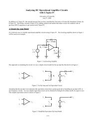
Figure 3 shows a circuit that uses a voltage-dependent voltage source. (This circuit uses the<br />
“v_<strong>of</strong>_v_2” source in which the voltage polarity <strong>of</strong> the sensing terminals is opposite that <strong>of</strong> the<br />
“v_<strong>of</strong>_v_1” source. Either source can be used with equivalent results in any circuit. Using the<br />
“v_<strong>of</strong>_v_2” source in this schematic allows the schematic to be drawn without crossing any wires.)<br />
<strong>The</strong> voltage produced by the dependent source is twice the voltage across resistor R1 (as measure from<br />
the left side <strong>of</strong> the resistor to the right side <strong>of</strong> the resistor). Note that making connections to the sensing<br />
pair <strong>of</strong> terminals has no effect on the rest <strong>of</strong> the circuit.<br />
Figure 3: Example Use <strong>of</strong> the Voltage Dependent Voltage Source<br />
<strong>The</strong> LTspice <strong>IV</strong> and UE voltage-dependent current sources are shown in Figure 4. <strong>The</strong> LTspice <strong>IV</strong><br />
symbol name is “g” while that for the UE symbol is “i_<strong>of</strong>_v_1”. <strong>The</strong>y produce a current which is a<br />
multiple <strong>of</strong> the voltage at the sensing pair <strong>of</strong> terminals. Connections to the sensing pair <strong>of</strong> terminals are<br />
made similarly to the voltage-dependent voltage source.<br />
Figure 4: LTspice <strong>IV</strong> and UE Voltage Dependent Current Source Symbols<br />
<strong>The</strong> LTspice <strong>IV</strong> and UE current-dependent current sources are shown in Figure 5. <strong>The</strong> LTspice <strong>IV</strong><br />
name for this symbol is “f” while the UE symbol name is “i_<strong>of</strong>_i_1”. <strong>The</strong>se sources produce a current<br />
that is a constant multiple <strong>of</strong> another current in the circuit. <strong>The</strong> UE component is much simpler to use<br />
than the LTspice <strong>IV</strong> component and only its operation will be described here. <strong>The</strong> UE symbol includes
a sensing wire. <strong>The</strong> current gain is changed by right-clicking on the source and changing the value Ai<br />
in the <strong>Component</strong> Attribute Editor.<br />
Figure 5: LTspice <strong>IV</strong> and UE Current Dependent Current Source Symbols<br />
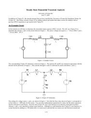
Figure 6 shows an example circuit using the current dependent current source. In this example the<br />
current source is producing a current equal to twice the current flowing (from left-to-right) through<br />
resistor R1. (Note that the assumed positive direction <strong>of</strong> the sensing current is in the direction <strong>of</strong> the<br />
arrow next to the sensing wire.) <strong>The</strong> sensing wire is a short circuit and must be placed in series with<br />
whichever component whose current you are sensing.<br />
Figure 6: Example Use <strong>of</strong> the Current-Dependent Current Source<br />
<strong>The</strong> LTspice <strong>IV</strong> and UE current-dependent voltage sources are shown in Figure 7. <strong>The</strong> LTspice <strong>IV</strong><br />
symbol name is “h” while that for the UE symbol is “v_<strong>of</strong>_i_1”. <strong>The</strong>y produce a voltage which is a<br />
multiple <strong>of</strong> the current flowing elsewhere in the circuit. <strong>The</strong> UE symbol includes a sensing wire.<br />
Connections the sensing wire are made similarly to the current-dependent current source.<br />
Diodes<br />
Figure 7: LTspice <strong>IV</strong> and UE Current Dependent Voltage Source Symbols
Transistors<br />
Op Amps