Modeling Diode Circuits with MicroCap 7.0 - csserver - University of ...
Modeling Diode Circuits with MicroCap 7.0 - csserver - University of ...
Modeling Diode Circuits with MicroCap 7.0 - csserver - University of ...

You also want an ePaper? Increase the reach of your titles
YUMPU automatically turns print PDFs into web optimized ePapers that Google loves.
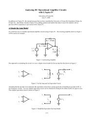
Figure 4: <strong>MicroCap</strong> Simple <strong>Diode</strong> Test Results<br />
<strong>Modeling</strong> the Reverse Bias Region<br />
The Reverse Breakdown Parameters: BV and IBV<br />
The default reverse breakdown (Zener) voltage is infinite. Obviously we need to change<br />
this if we are trying to accurately model a Zener diode. There are two parameters that<br />
need to be set to model the Zener breakdown region: BV is the breakdown voltage and<br />
IBV is current at the breakdown voltage. To model an 8 V Zener diode, typical values<br />
for these parameters might be:<br />
BV = 8 V<br />
IBV = 20 mA<br />
Note that BV is set to a positive value although on a typical characteristic curve the<br />
breakdown voltage is negative. These values were used in the diode in Figure 3. A DC<br />
analysis was performed and the source voltage was swept from -60 V to 50 V. Figure 5<br />
shows the result.<br />
A.M. Richardson Page 4 <strong>of</strong> 8 September 2, 2002