ATtiny2313 Datasheet - DCE FEL ČVUT v Praze
ATtiny2313 Datasheet - DCE FEL ČVUT v Praze
ATtiny2313 Datasheet - DCE FEL ČVUT v Praze

You also want an ePaper? Increase the reach of your titles
YUMPU automatically turns print PDFs into web optimized ePapers that Google loves.
Timer/Counter<br />
Interrupt Flag Register<br />
– TIFR<br />
112<br />
<strong>ATtiny2313</strong><br />
When this bit is written to one, and the I-flag in the Status Register is set (interrupts globally<br />
enabled), the Timer/Counter1 Input Capture interrupt is enabled. The corresponding Interrupt<br />
Vector (See “Interrupts” on page 46.) is executed when the ICF1 flag, located in TIFR, is set.<br />
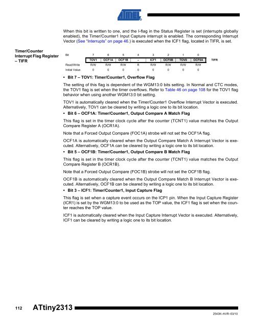
Bit 7 6 5 4 3 2 1 0<br />
TOV1 OCF1A OCF1B – ICF1 OCF0B TOV0 OCF0A TIFR<br />
Read/Write R/W R/W R/W R R/W R/W R/W R/W<br />
Initial Value 0 0 0 0 0 0 0 0<br />
• Bit 7 – TOV1: Timer/Counter1, Overflow Flag<br />
The setting of this flag is dependent of the WGM13:0 bits setting. In Normal and CTC modes,<br />
the TOV1 flag is set when the timer overflows. Refer to Table 46 on page 108 for the TOV1 flag<br />
behavior when using another WGM13:0 bit setting.<br />
TOV1 is automatically cleared when the Timer/Counter1 Overflow Interrupt Vector is executed.<br />
Alternatively, TOV1 can be cleared by writing a logic one to its bit location.<br />
• Bit 6 – OCF1A: Timer/Counter1, Output Compare A Match Flag<br />
This flag is set in the timer clock cycle after the counter (TCNT1) value matches the Output<br />
Compare Register A (OCR1A).<br />
Note that a Forced Output Compare (FOC1A) strobe will not set the OCF1A flag.<br />
OCF1A is automatically cleared when the Output Compare Match A Interrupt Vector is executed.<br />
Alternatively, OCF1A can be cleared by writing a logic one to its bit location.<br />
• Bit 5 – OCF1B: Timer/Counter1, Output Compare B Match Flag<br />
This flag is set in the timer clock cycle after the counter (TCNT1) value matches the Output<br />
Compare Register B (OCR1B).<br />
Note that a Forced Output Compare (FOC1B) strobe will not set the OCF1B flag.<br />
OCF1B is automatically cleared when the Output Compare Match B Interrupt Vector is executed.<br />
Alternatively, OCF1B can be cleared by writing a logic one to its bit location.<br />
• Bit 3 – ICF1: Timer/Counter1, Input Capture Flag<br />
This flag is set when a capture event occurs on the ICP1 pin. When the Input Capture Register<br />
(ICR1) is set by the WGM13:0 to be used as the TOP value, the ICF1 flag is set when the counter<br />
reaches the TOP value.<br />
ICF1 is automatically cleared when the Input Capture Interrupt Vector is executed. Alternatively,<br />
ICF1 can be cleared by writing a logic one to its bit location.<br />
2543K–AVR–03/10