ATtiny2313 Datasheet - DCE FEL ČVUT v Praze
ATtiny2313 Datasheet - DCE FEL ČVUT v Praze
ATtiny2313 Datasheet - DCE FEL ČVUT v Praze

Create successful ePaper yourself
Turn your PDF publications into a flip-book with our unique Google optimized e-Paper software.
Oscillator Calibration<br />
Register – OSCCAL<br />
28<br />
<strong>ATtiny2313</strong><br />
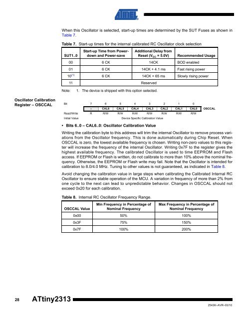
When this Oscillator is selected, start-up times are determined by the SUT Fuses as shown in<br />
Table 7.<br />
Table 7. Start-up times for the internal calibrated RC Oscillator clock selection<br />
SUT1..0<br />
Start-up Time from Powerdown<br />
and Power-save<br />
Note: 1. The device is shipped with this option selected.<br />
Additional Delay from<br />
Reset (V CC = 5.0V) Recommended Usage<br />
00 6 CK 14CK BOD enabled<br />
01 6 CK 14CK + 4.1 ms Fast rising power<br />
10 (1)<br />
6 CK 14CK + 65 ms Slowly rising power<br />
11 Reserved<br />
Bit 7 6 5 4 3 2 1 0<br />
– CAL6 CAL5 CAL4 CAL3 CAL2 CAL1 CAL0 OSCCAL<br />
Read/Write R R/W R/W R/W R/W R/W R/W R/W<br />
Initial Value Device Specific Calibration Value<br />
• Bits 6..0 – CAL6..0: Oscillator Calibration Value<br />
Writing the calibration byte to this address will trim the internal Oscillator to remove process variations<br />
from the Oscillator frequency. This is done automatically during Chip Reset. When<br />
OSCCAL is zero, the lowest available frequency is chosen. Writing non-zero values to this register<br />
will increase the frequency of the internal Oscillator. Writing 0x7F to the register gives the<br />
highest available frequency. The calibrated Oscillator is used to time EEPROM and Flash<br />
access. If EEPROM or Flash is written, do not calibrate to more than 10% above the nominal frequency.<br />
Otherwise, the EEPROM or Flash write may fail. Note that the Oscillator is intended for<br />
calibration to 8.0/4.0 MHz. Tuning to other values is not guaranteed, as indicated in Table 8.<br />
Avoid changing the calibration value in large steps when calibrating the Calibrated Internal RC<br />
Oscillator to ensure stable operation of the MCU. A variation in frequency of more than 2% from<br />
one cycle to the next can lead to unpredictable behavior. Changes in OSCCAL should not<br />
exceed 0x20 for each calibration.<br />
Table 8. Internal RC Oscillator Frequency Range.<br />
OSCCAL Value<br />
Min Frequency in Percentage of<br />
Nominal Frequency<br />
Max Frequency in Percentage of<br />
Nominal Frequency<br />
0x00 50% 100%<br />
0x3F 75% 150%<br />
0x7F 100% 200%<br />
2543K–AVR–03/10