weld 1100 - shielded metal arc welding - College of Eastern Utah
weld 1100 - shielded metal arc welding - College of Eastern Utah
weld 1100 - shielded metal arc welding - College of Eastern Utah

Create successful ePaper yourself
Turn your PDF publications into a flip-book with our unique Google optimized e-Paper software.
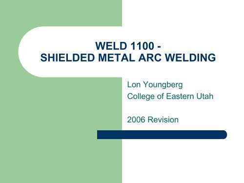
WELD <strong>1100</strong> -<br />
SHIELDED METAL ARC WELDING<br />
Lon Youngberg<br />
<strong>College</strong> <strong>of</strong> <strong>Eastern</strong> <strong>Utah</strong><br />
2006 Revision
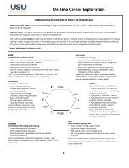
Main Areas <strong>of</strong> Study<br />
Welding Safety<br />
Intro to Welding Power<br />
Shielded Metal Arc Welding - Chapter 2<br />
Electrode Classification and Selection<br />
Common Terminology<br />
Oxy-Fuel Cutting - Chapter 14
Input Power<br />
Common household power is single phase 120 volts,<br />
alternating current (120VAC) at 60 hertz frequency. Most<br />
households also contain single phase 220 VAC for heavy duty<br />
appliances (clothes dryers and furnaces).<br />
Heavy industry also has single phase 120 and 220 VAC for<br />
running lights and low-power appliances. However, most<br />
heavy industrial equipment operates from 3-phase power at<br />
voltages ranging from 220 to 480 VAC.<br />
A <strong>weld</strong>ing power source must convert high voltage/low current<br />
input power to low voltage/high amperage <strong>weld</strong>ing current.
Output Power<br />
The electricity coming out <strong>of</strong> <strong>weld</strong>ing power<br />
sources can be either Alternating Current<br />
(AC), Direct Current Electrode Positive<br />
(DCEP also called Reverse Polarity), or<br />
Direct Current Electrode Negative (DCEN<br />
also called Straight Polarity).<br />
– REPublican SENator<br />
(handout or demo for switching polarity.)
Output Power (cont.)<br />
Typical open circuit voltage for the SMAW process is 60 to<br />
80 Volts.<br />
Typical <strong>arc</strong> voltage (while <strong>weld</strong>ing) is 23 to 27 volts. A<br />
short <strong>arc</strong> gap will cause the number to be lower and a long<br />
<strong>arc</strong> gap will cause it to be higher.<br />
The amperage is set by the knob on the SMAW machine<br />
and typically ranges from about 60 amps to 200 amps.<br />
A recommended amperage range is available for every<br />
type and size <strong>of</strong> rod. Then you adjust up or down from the<br />
middle <strong>of</strong> the range depending on <strong>weld</strong>ing position,<br />
desired depth <strong>of</strong> penetration, joint type, etc..
Output Power (cont.)<br />
Welding machines are designed to deliver<br />
constant current output, constant voltage<br />
output, or some can provide both at the turn<br />
<strong>of</strong> a switch/knob.<br />
– Constant Current (CC) - Is used for SMAW<br />
and GTAW processes.<br />
– Constant Voltage (CV) – Is used for GMAW<br />
and FCAW processes.
Welding Machine Types<br />
1. AC Transformer<br />
2. Transformer / Rectifier<br />
3. Motor Generator (obsolete)<br />
4. Inverter<br />
5. Engine Generator<br />
– Notice that machines are not classified by <strong>weld</strong>ing process<br />
because most will do more than one process. The<br />
advanced SMAW class will discuss <strong>weld</strong>ing power in<br />
greater depth.
Shielded Metal Arc Welding<br />
“Shielded Metal Arc Welding (SMAW) is an <strong>arc</strong><br />
<strong>weld</strong>ing process in which coalescence <strong>of</strong> <strong>metal</strong>s<br />
is produced between the tip <strong>of</strong> a covered<br />
electrode and the surface <strong>of</strong> the base <strong>metal</strong> in the<br />
joint being <strong>weld</strong>ed.” (AWS Handbook, vol. 2)<br />
SMAW is the most widely used <strong>of</strong> all the <strong>arc</strong><br />
<strong>weld</strong>ing processes.<br />
Temperatures above 9,000F are produced at the<br />
<strong>arc</strong> center.
SMAW
Functions <strong>of</strong> the Electrode<br />
Covering (flux):<br />
Decomposition <strong>of</strong> the electrode cover (during <strong>weld</strong>ing)<br />
provides a shielding gas (generally CO, CO 2, H 2 or even H 2O)<br />
to prevent air from contaminating the <strong>weld</strong> pool.<br />
Provides scavenging, deoxidizing and fluxing agents to<br />
cleanse <strong>weld</strong>, prevent excessive grain growth and improve<br />
wetting action. (See next slide)<br />
Determines the electrical characteristics <strong>of</strong> the electrode<br />
(ionization potential <strong>of</strong> the shielding gas determines AC/DC).<br />
Produces a slag blanket to protect the solidified <strong>weld</strong>.<br />
Influences the mechanical properties and bead shape.<br />
Provides a method for introducing alloying elements and<br />
thereby effect the mechanical and/or corrosion properties.
Example <strong>of</strong> Composition and Function <strong>of</strong><br />
Electrode Covering:
The Primary Effects <strong>of</strong> Common Alloying Elements<br />
in Carbon Steel:<br />
Carbon (C)- Increases strength, hardness and cracking tendency.<br />
Chromium (Cr)- Increases corrosion resistance and hardenability.<br />
Manganese (Mn)- Improves strength and hardenability, deoxidizes.<br />
Aluminum (Al), Silicon (Si) & Titanium (Ti)- Serve as a deoxidizers.<br />
Nickel (Ni)- Improves toughness while mildly increasing strength!<br />
Molybdenum (Mo)- Improves stength at elevated temperatures,<br />
increases hardenability.<br />
Sulfur (S), Selenium (Se), Lead (Pb) and Phosphorus (P) - Are not<br />
intentionally added to <strong>weld</strong> <strong>metal</strong> or steel intended for <strong>weld</strong>ing. The<br />
elements may be present as impurities and should not be present in<br />
<strong>weld</strong>ments at levels above about 0.04%. These elements are <strong>of</strong>ten<br />
intentionally added to improve machinabilty in “free machining steels”.
Covered Electrode Quick Facts:<br />
Iron Powder is <strong>of</strong>ten included in the electrode covering to<br />
increase deposition. Electrodes with heavy iron powder<br />
coatings (E7024) require less skill because the <strong>weld</strong>er can<br />
simply “drag” the rod along the joint.<br />
Electrode coverings are applied to the core-rod by extrusion or<br />
dipping. Extrusion is most common.<br />
Some rods convert their covering into mostly gas (E6010) and<br />
produce a light slag. Other rods produce less gas and a heavy<br />
slag (E6013). Thus a spectrum exists from primarily gas to<br />
primarily slag shielding.<br />
Electrode Lengths <strong>of</strong> 9 to 18 inches are available.
SMAW Capabilities and<br />
Limitations:<br />
Simple, inexpensive and portable equipment.<br />
Covered electrode provides both filler <strong>metal</strong> and shielding<br />
method.<br />
Less sensitive to drafts/wind than gas-<strong>shielded</strong> processes.<br />
Can be used in areas with limited access.<br />
Suitable for most common alloys.<br />
Suitable for sheet <strong>metal</strong> (1/16” min.) or thick sections.<br />
Operator duty cycle and deposition rates are lower than with wire<br />
feed processes.<br />
Slag must be removed, (unlike GMAW or GTAW).
SMAW Equipment<br />
Review the CC volt-ampere curve (see next slide), Open circuit<br />
voltage, and power source selection from chapter 2 and the prior<br />
power source notes.<br />
Welding Cables- The size (diameter) is determined by the cable<br />
length and maximum amperage to be used. Table 2.1 provides<br />
recommended sizes.<br />
Electrode Holder- Select the smallest, most comfortable holder<br />
that is rated for required amperage.<br />
Ground Clamp- Spring or screw mechanism?<br />
Personal Equipment- Helment, dark lenses, safety glasses,<br />
gloves, chipping hammer, wire brush and protective clothing.
Constant Current<br />
Volt-Ampere Curve:
Base Metals and Electrodes:<br />
Base Metal Example<br />
Base Metal<br />
Carbon Steel AISI 1018,<br />
ASTM A36, A516<br />
Low-Alloy Steel AISI 4140, 8620<br />
ASTM A514, A519<br />
Stainless Steel AISI 304, 316,<br />
410, ASTM A240<br />
Cast Iron Ductile Iron<br />
Grey Iron<br />
Aluminum A356, 5052,<br />
3003, 6061-T6<br />
Copper Alloys B505 UNS C95400<br />
Brass, Bronze,<br />
Nickel Alloys Inconel 625,<br />
Hastelloy C22<br />
AWS Electrode Example<br />
Specification Electrodes<br />
A5.1 E6010, E6013,<br />
E7018, E7024<br />
A5.5 E8018-C1<br />
E9018-B2<br />
A5.4 E308L, E316L,<br />
E410NiMo<br />
A5.15 ENi-CI<br />
EniCu-A<br />
A5.3 E<strong>1100</strong><br />
E4043<br />
A5.6 ECuAl-A2<br />
ECuMnNiAl<br />
A5.11 ERNiCrMo-3<br />
ERNiFe-1
Base Metals and Electrodes<br />
Continued:<br />
Surfacing Electrodes (per AWS A5.13) are commonly used for special<br />
applications such as Corrosion, Wear or Impact resistant deposits.<br />
Special <strong>metal</strong>lurgical or dimensional properties can also be achieved by<br />
strategically selecting your electrode.<br />
Electrode Coverings are “Hygroscopic” --- They will absorb moisture<br />
from the atmosphere. Some electrodes are intended to be “lowhydrogen”<br />
and must be properly packaged and stored to prevent<br />
moisture absorption. As the humidity level and base <strong>metal</strong>/electrode<br />
strength increase, the likelihood <strong>of</strong> hydrogen cracking (due to damp<br />
electrodes) also increase. Low-alloy electrodes ending with 15, 16 or<br />
18 (E7018) are low-hydrogen types. Rod ovens are typically<br />
maintained at 250F.<br />
Most SMAW is performed on <strong>metal</strong> between 1/8” and 1.5” thick. Thicker<br />
materials are more economically <strong>weld</strong>ed with FCAW or SAW
Welding Positions:<br />
- Fillet Welds on Plate
Welding Positions:<br />
- Fillet Welds on Pipe
Welding Positions:<br />
- Butt Welds on Plate
Welding<br />
Positions:
Basic Weld Joints
Weld Backing - Supports Weld Pool and<br />
Provides Root Contour.<br />
4 Types <strong>of</strong> Backing:<br />
– Backing Strip - Usually made from the same material as the<br />
<strong>weld</strong> joint. The root pass <strong>weld</strong>s the backing strip to the back <strong>of</strong><br />
the joint. Can be left in place or removed later.<br />
– Copper Backing Bar - Does not fuse (<strong>weld</strong>) to the joint.<br />
Supports the molten <strong>weld</strong> puddle. Used for its high thermal<br />
conductivity. (Aluminum is also sometimes used.)<br />
– Non<strong>metal</strong>lic Backing - Usually consists <strong>of</strong> ceramic segments<br />
or a granular flux.<br />
– Backing Weld - A <strong>weld</strong> made from the back-side <strong>of</strong> the joint<br />
before the groove is filled from the face side.
Joint Geometry and Fit-Up<br />
Fit-Up - Refers to the quality <strong>of</strong> joint dimensions and alignment.<br />
You cannot make a high quality <strong>weld</strong> with poor quality fit-up.<br />
Joint Geometry - Refers to the shape and dimensions <strong>of</strong> a joint<br />
prior to <strong>weld</strong>ing.<br />
– The book provides numerous examples <strong>of</strong> common joint<br />
geometry (dimensions/angles).<br />
– See Joint Geometry and terminology handout.<br />
Run<strong>of</strong>f Tabs - See figure 2.9<br />
Preheat - Heating the joint area prior/during <strong>weld</strong>ing.
Electrode Factors<br />
Electrode Diameter Depends on:<br />
– Base Metal Thickness >Welding Position<br />
– Type <strong>of</strong> Weld Joint >Power Source Rating<br />
The proper electrode diameter will produce a <strong>weld</strong><br />
<strong>of</strong> the required size and quality in the minimum<br />
amount <strong>of</strong> time.<br />
Deposition rate (lbs/hr) increases as the electrode<br />
diameter increases.<br />
Electrode Orientation - Study Table 2.3
Welding Technique<br />
Striking the Arc: >Tap or Scratch technique<br />
Strike E7018 ahead <strong>of</strong> the intended start location then quickly<br />
move to the start position and <strong>weld</strong> over where the <strong>arc</strong> was<br />
struck.<br />
Breaking the Arc: When you run out <strong>of</strong> rod, push the stub down<br />
tight on the puddle, then quickly pull it aside. This leaves a<br />
clean crater to start the next rod.<br />
When starting from a crater, strike the <strong>arc</strong> at the front end <strong>of</strong> the<br />
crater, then quickly move to the back and proceed forward to<br />
continue the <strong>weld</strong>.
Slag Removal<br />
Slag inclusions are <strong>of</strong>ten caused by inadequate slag removal.<br />
Each bead must be thoroughly cleaned prior to <strong>weld</strong>ing over it.<br />
Slag removal is easier when there is a smooth transition from<br />
bead to bead or the base material to the bead(s).<br />
Slag entrapment <strong>of</strong>ten occurs where sharp notches are formed.<br />
Undercutting, overlapping and excessive bead convexity promote<br />
slag entrapment and inclusions.<br />
Complete removal <strong>of</strong> slag is required to achieve high quality<br />
<strong>weld</strong>s.
Weld Quality<br />
Arc Blow – Colliding magnetic fields.<br />
– A magnetic field in the base <strong>metal</strong>, table or fixture interacts<br />
with the magnetic field surrounding the <strong>weld</strong> rod. Can cause<br />
porosity, slag inclusions, lack <strong>of</strong> fusion and other flaws.<br />
– Corrective Actions: 1. Short <strong>arc</strong> gap, 2. Change rod angle to<br />
counteract, 3. move work clamp, 4. Change <strong>weld</strong>ing<br />
direction, 5. Use back-step technique, 6. Change from DC to<br />
AC, 7. Add run<strong>of</strong>f plates & Tabs, 8. Last Resort: Wrap work<br />
cable around work piece a few times.<br />
Porosity – Gas bubbles<br />
– Usually caused by contaminated rod or base <strong>metal</strong>.<br />
Slag Inclusions – Non-<strong>metal</strong>lic inclusions<br />
– Causes: poor cleaning, rod angle (drag), amperage (too low),<br />
and bead placement.
Weld Quality (cont.)<br />
Incomplete Fusion – Failure to join/fuse<br />
– Causes: poor bead placement, convex beads,<br />
large “rolling” puddle, wrong amperage<br />
Undercut – “Ditched” at toes<br />
– Causes: excessive current, poor rod angle.<br />
Cracks –Numerous types.<br />
– As a <strong>weld</strong>er, you need to take care <strong>of</strong> crater<br />
cracks by filling your crater at <strong>weld</strong> completion.