

Chapter 15 Pulse-Width Modulation Subsystem (PWMSS).
Chapter 15 Pulse-Width Modulation Subsystem (PWMSS).
Chapter 15 Pulse-Width Modulation Subsystem (PWMSS).

Create successful ePaper yourself
Turn your PDF publications into a flip-book with our unique Google optimized e-Paper software.
<strong>Pulse</strong>-<strong>Width</strong> <strong>Modulation</strong> <strong>Subsystem</strong> (<strong>PWMSS</strong>) www.ti.com<br />
<strong>15</strong>.1 <strong>Pulse</strong>-<strong>Width</strong> <strong>Modulation</strong> <strong>Subsystem</strong> (<strong>PWMSS</strong>)<br />
<strong>15</strong>.1.1 Introduction<br />
<strong>15</strong>.1.1.1 Features<br />
The general features of the <strong>PWMSS</strong> are:<br />
eHRPWM<br />
• Dedicated 16 bit time-base with Period / Frequency control<br />
• Can support 2 independent PWM outputs with Single edge operation<br />
• Can support 2 independent PWM outputs with Dual edge symmetric operation<br />
• Can support 1 independent PWM output with Dual edge asymmetric operation<br />
• Supports Dead-band generation with independent Rising and Falling edge delay control<br />
• Provides asynchronous over-ride control of PWM signals during fault conditions<br />
• Supports “trip zone” allocation of both latched and un-latched fault conditions<br />
• Allows events to trigger both CPU interrupts and start of ADC conversions<br />
• Support PWM chopping by high frequency carrier signal, used for pulse transformer gate drives.<br />
• High-resolution module with programmable delay line.<br />
eCAP<br />
– Programmable on a per PWM period basis.<br />
– Can be inserted either on the rising edge or falling edge of the PWM pulse or both or not at all.<br />
• Dedicated input Capture pin<br />
• 32 bit Time Base (counter)<br />
• 4 x 32 bit Time-stamp Capture registers (CAP1-CAP4)<br />
• 4 stage sequencer (Mod4 counter) which is synchronized to external events (ECAPx pin edges)<br />
• Independent Edge polarity (Rising / Falling edge) selection for all 4 events<br />
• Input Capture signal pre-scaling (from 1 to 16)<br />
• One-shot compare register (2 bits) to freeze captures after 1 to 4 Time-stamp events<br />
• Control for continuous Time-stamp captures using a 4 deep circular buffer (CAP1-CAP4) scheme<br />
• Interrupt capabilities on any of the 4 capture events<br />
eQEP<br />
• Input Synchronization<br />
• Three Stage/Six Stage Digital Noise Filter<br />
• Quadrature Decoder Unit<br />
• Position Counter and Control unit for position measurement<br />
• Quadrature Edge Capture unit for low speed measurement<br />
• Unit Time base for speed/frequency measurement<br />
• Watchdog Timer for detecting stalls<br />
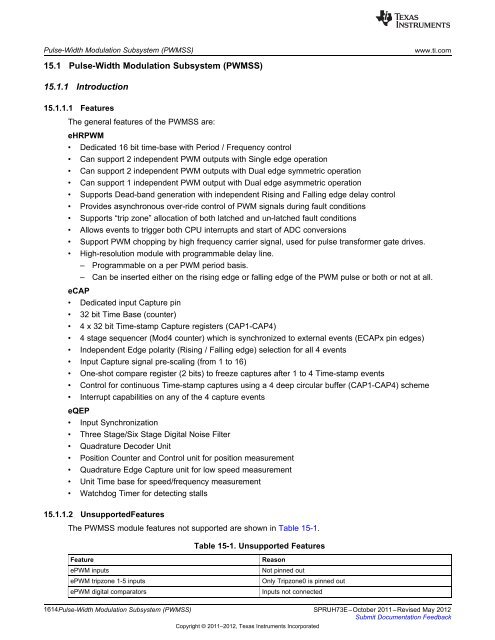
<strong>15</strong>.1.1.2 UnsupportedFeatures<br />
The <strong>PWMSS</strong> module features not supported are shown in Table <strong>15</strong>-1.<br />
Table <strong>15</strong>-1. Unsupported Features<br />
Feature Reason<br />
ePWM inputs Not pinned out<br />
ePWM tripzone 1-5 inputs Only Tripzone0 is pinned out<br />
ePWM digital comparators Inputs not connected<br />
1614<strong>Pulse</strong>-<strong>Width</strong> <strong>Modulation</strong> <strong>Subsystem</strong> (<strong>PWMSS</strong>) SPRUH73E–October 2011–Revised May 2012<br />
Submit Documentation Feedback<br />
Copyright © 2011–2012, Texas Instruments Incorporated


