Working Model - MAELabs UCSD
Working Model - MAELabs UCSD
Working Model - MAELabs UCSD

You also want an ePaper? Increase the reach of your titles
YUMPU automatically turns print PDFs into web optimized ePapers that Google loves.
WM52ProductGuide.fm Page 22 Tuesday, March 2, 2004 12:04 PM<br />
22<br />
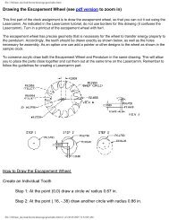
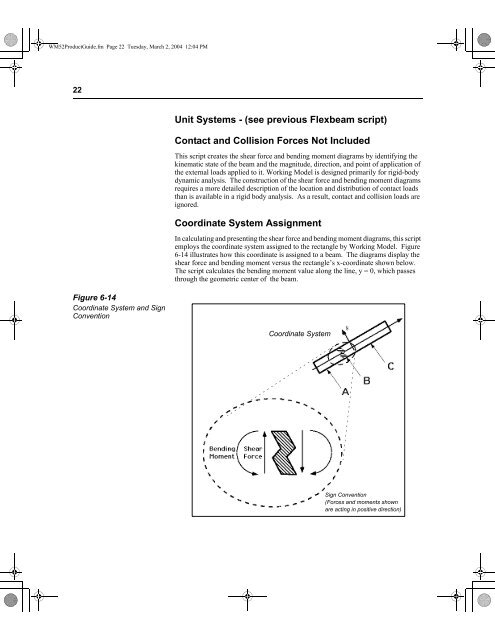
Figure 6-14<br />
Coordinate System and Sign<br />
Convention<br />
Unit Systems - (see previous Flexbeam script)<br />
Contact and Collision Forces Not Included<br />
This script creates the shear force and bending moment diagrams by identifying the<br />
kinematic state of the beam and the magnitude, direction, and point of application of<br />
the external loads applied to it. <strong>Working</strong> <strong>Model</strong> is designed primarily for rigid-body<br />
dynamic analysis. The construction of the shear force and bending moment diagrams<br />
requires a more detailed description of the location and distribution of contact loads<br />
than is available in a rigid body analysis. As a result, contact and collision loads are<br />
ignored.<br />
Coordinate System Assignment<br />
In calculating and presenting the shear force and bending moment diagrams, this script<br />
employs the coordinate system assigned to the rectangle by <strong>Working</strong> <strong>Model</strong>. Figure<br />
6-14 illustrates how this coordinate is assigned to a beam. The diagrams display the<br />
shear force and bending moment versus the rectangle’s x-coordinate shown below.<br />
The script calculates the bending moment value along the line, y = 0, which passes<br />
through the geometric center of the beam.<br />
Coordinate System<br />
Sign Convention<br />
(Forces and moments shown<br />
are acting in positive direction)