Working Model - MAELabs UCSD
Working Model - MAELabs UCSD
Working Model - MAELabs UCSD

Create successful ePaper yourself
Turn your PDF publications into a flip-book with our unique Google optimized e-Paper software.
WM52ProductGuide.fm Page 1 Tuesday, March 2, 2004 12:04 PM<br />
<strong>Working</strong> <strong>Model</strong><br />
Version 5.2<br />
For Windows ® 95/98/ME/2000/XP/NT ® 4.0 and later<br />
Product Guide<br />
Contents:<br />
TM<br />
• What’s in This Package?<br />
• System Requirements<br />
• Installing and Launching Interactive Physics<br />
• Concurrent Network Licenses<br />
• Technical Support and Other Services<br />
• Troubleshooting and Helpful Suggestions<br />
• Limitations<br />
• New Features<br />
• Version Comparison<br />
1
WM52ProductGuide.fm Page 2 Tuesday, March 2, 2004 12:04 PM<br />
2<br />
Information in this document is subject to change without notice and does not represent a commitment on the part of<br />
MSC.Software Corporation. The software described in this document is furnished under a license agreement or nondisclosure<br />
agreement. The software may be used or copied only in accordance with the terms of the agreement. It is<br />
against the law to copy the software on any medium except as specifically allowed in the license or non-disclosure<br />
agreement. No part of this manual may be reproduced or transmitted in any form or by any means, electronic or<br />
mechanical, including photocopying and recording, for any purpose without the express written permission of<br />
MSC.Software Corporation.<br />
© Copyright MSC.Software Corporation 2001. All rights reserved. Published and printed in the U.S.A.<br />
Portions © 1992-1995 Summit Software Company.<br />
Interactive Physics, Interactive Physics II, Interactive Physics Player, Smart Editor, <strong>Working</strong> <strong>Model</strong>, <strong>Working</strong> <strong>Model</strong><br />
Basic and WM Basic are trademarks of MSC.Software Corporation.<br />
MSC, the MSC.Software logo, and Knowledge Revolution are registered trademarks of MSC.Software Corporation.<br />
Apple, Macintosh, Mac, and QuickTime are registered trademarks of Apple Computer, Incorporated.<br />
AppleGuide is a trademark of Apple Computer, Incorporated.<br />
Microsoft, Windows, and Windows NT are registered trademarks of Microsoft Corporation.<br />
WinHelp is a trademark of Microsoft Corporation.<br />
PowerPC, Lotus, and 1-2-3 are registered trademarks of International Business Machines Corporation.<br />
MATLAB is a registered trademark of the MathWorks, Incorporated.<br />
Quattro Pro is a registered trademark of Corel Corporation.<br />
AutoCAD is a registered trademark of AutoDesk, Incorporated.<br />
DXF is a trademark of AutoDesk, Incorporated.<br />
Claris and FileMaker are registered trademarks of Claris Corporation.<br />
MacroMind Three-D is a trademark of Macromedia, Inc.<br />
Wavefront Technology’s Advanced Visualizer is a trademark of Alias|Wavefront, a division of Silicon Graphics Limited.<br />
Electric Image is a trademark of Electric Image, Inc.<br />
All other brand or product names are trademarks or registered trademarks of their respective holders.<br />
http://www.workingmodel.com
WM52ProductGuide.fm Page 3 Tuesday, March 2, 2004 12:04 PM<br />
<strong>Working</strong> <strong>Model</strong> Product Guide<br />
Congratulations on your purchase of <strong>Working</strong> <strong>Model</strong>!<br />
1. What’s in This Package? 3<br />
<strong>Working</strong> <strong>Model</strong>, the world’s most popular CAE tool, changes the way engineers<br />
design and develop mechanical systems.<br />
Please Register!<br />
Please make sure to either fax or mail the registration card enclosed. Once you have<br />
registered, we will notify you about periodic software updates.<br />
This Product Guide covers the following areas:<br />
• What’s in This Package?<br />
• System Requirements<br />
• Installing and Launching <strong>Working</strong> <strong>Model</strong><br />
• Scripts<br />
• Technical Support and Other Services<br />
• Troubleshooting and Helpful Suggestions<br />
• Limitations<br />
• New Features<br />
1. What’s in This Package?<br />
This package contains the following:<br />
• <strong>Working</strong> <strong>Model</strong> CD-ROM for installation<br />
• Product Registration Card<br />
• MSC.Software Software License Agreement<br />
• Product Guide (this document, with new feature documentation)<br />
The <strong>Working</strong> <strong>Model</strong> CD-ROM contains:<br />
• Windows ® version 5.2 and MacOS version 4.0 of <strong>Working</strong> <strong>Model</strong><br />
• Windows ® version 5.2 of <strong>Working</strong> <strong>Model</strong> in Japanese
WM52ProductGuide.fm Page 4 Tuesday, March 2, 2004 12:04 PM<br />
4<br />
2. System Requirements<br />
Windows System Requirements<br />
• Windows 95/98/Me/2000/XP or Windows NT 4.0 (or later)<br />
• 64 MB of RAM<br />
• 60 MB of hard disk space for a full installation<br />
• CD-ROM drive (for installation)<br />
• Sound card (for audio effects)<br />
MacOS System Requirements<br />
• PowerPC-based systems<br />
• MacOS System 7.1 or above<br />
• 64 MB of RAM<br />
• 60 MB of hard disk space for a full installation<br />
• CD-ROM drive (for installation)<br />
3. Installing and Launching <strong>Working</strong><br />
<strong>Model</strong><br />
NOTE: If you are installing on Windows NT or Windows 2000, you must be logged<br />
in with administrator-level privilege.<br />
Insert the CD-ROM in your drive. If the Windows AutoRun utility is activated, the<br />
Installation Screen will automatically appear. If AutoRun is not activated, doubleclick<br />
the Setup.exe file located on the CD-ROM to launch the Installation Screen.<br />
Select the language you want.<br />
You will need a valid serial number to complete the installation. You may install a<br />
demo version of the software by typing Demo in the serial number box. The demo<br />
version does not permit saving, printing, or exporting of files.<br />
See “Concurrent Network Licenses” for network installation instructions.
WM52ProductGuide.fm Page 5 Tuesday, March 2, 2004 12:04 PM<br />
3. Installing and Launching <strong>Working</strong> <strong>Model</strong> 5<br />
3.1 Attaching the Hardware Key (Professional<br />
Product)<br />
Before you launch <strong>Working</strong> <strong>Model</strong>, please make sure to attach the hardware key to the<br />
parallel port of your computer. You can attach the hardware key between your parallel<br />
port and printer cable.<br />
The following figure shows an example of the 25-pin parallel port.<br />
The hardware key needs to be attached at all times while running <strong>Working</strong> <strong>Model</strong>. If<br />
the hardware key is removed, <strong>Working</strong> <strong>Model</strong> prompts you to reattach the key or quit<br />
the application. (NOTE: The hardware key is NOT required during installation).<br />
If you do not have a hardware key, you can run <strong>Working</strong> <strong>Model</strong> in demo mode. All<br />
of the program’s features will be available, but you will not be able to save, print, or<br />
export<br />
If you have multiple parallel ports, attach the hardware key to LPT1. If <strong>Working</strong><br />
<strong>Model</strong> does not find the key, restart your computer and try another port. In the<br />
unlikely event that you need to configure the hardware key driver, see the document<br />
Readme.txt located in the Install\Setup\Sysadmin\Sentinel\ folder of the <strong>Working</strong><br />
<strong>Model</strong> CD-ROM.<br />
3.2 Launching <strong>Working</strong> <strong>Model</strong><br />
After the installation:<br />
25- pin Parallel Port<br />
• On Windows 95/98/Me/2000/XP or Windows NT 4.0: Both the Windows<br />
Desktop and the Start->Programs menu provides access to the “<strong>Working</strong><strong>Model</strong>”<br />
program icon.<br />
• On MacOS: Double-click the “<strong>Working</strong> <strong>Model</strong> 4.0” icon in the <strong>Working</strong> <strong>Model</strong><br />
2D folder. Please enter the registration information and proceed.<br />
NOTE: Macintosh users installing <strong>Working</strong> <strong>Model</strong> 4.0 should use the serial number<br />
W2E40-9999-0A023510, instead of the serial number shown on the license<br />
agreement, registration card, or back cover of the User’s Manual.
WM52ProductGuide.fm Page 6 Tuesday, March 2, 2004 12:04 PM<br />
6<br />
When <strong>Working</strong> <strong>Model</strong> launches, you will see a blank new document.<br />
A step-by-step introductory tutorial is available by clicking Start, then Programs,<br />
<strong>Working</strong><strong>Model</strong>, WMIntroduction. Double-click on WMGetttingStarted.pdf.<br />
You are strongly encouraged to go over the introductory tutorial. The tutorial<br />
shows you useful tips and features that make your experience with <strong>Working</strong> <strong>Model</strong><br />
more effortless and productive.<br />
4. Concurrent Network Licenses for<br />
Windows<br />
The <strong>Working</strong> <strong>Model</strong> executable can be installed anywhere on the network. The files<br />
need not be located on the NetSentinel server or a file server. The diagram below<br />
summarizes the operating principle of the network licensing with NetSentinel server.<br />
This section contains important information for network system administrators who<br />
wish to make <strong>Working</strong> <strong>Model</strong> accessible on a local area network (LAN).<br />
4.1 How does the Concurrent Network<br />
Licensing Work?<br />
<strong>Working</strong> <strong>Model</strong> employs the robust, versatile network licensing mechanism called<br />
NetSentinel, developed by Rainbow Technologies, Incorporated. The concurrent<br />
network licenses allow each copy of <strong>Working</strong> <strong>Model</strong> to poll your local area network<br />
to look for authorization to run.<br />
NetSentinel Server—Monitoring Agent for Your Network<br />
You need to assign one PC (in your network) to act as the NetSentinel server. This<br />
PC always runs a small software program to authorize any new request and to keep<br />
track of how many copies of <strong>Working</strong> <strong>Model</strong> are running concurrently. You can<br />
designate any PC on the network as the NetSentinel server by installing and running<br />
the necessary software.<br />
Note: The <strong>Working</strong> <strong>Model</strong> network licensing mechanism does not work<br />
over a subnet.
WM52ProductGuide.fm Page 7 Tuesday, March 2, 2004 12:04 PM<br />
4. Concurrent Network Licenses for Windows 7<br />
How Concurrent Network Licensing Works<br />
Supported Network Protocols<br />
1<br />
File Server (Optional)<br />
PC Acting as NetSentinel Server<br />
(NetSentinel Hardware Key Attached)<br />
2 3<br />
PCs on which <strong>Working</strong> <strong>Model</strong> Runs<br />
Network protocols supported by <strong>Working</strong> <strong>Model</strong> include NetBEUI, IPX/SPX, and<br />
TCP/IP. See “Enabling and Disabling Network Protocols” for more information.<br />
What If I Already Have Stand-alone License(s)?<br />
Stand-alone licenses and concurrent network licenses can co-exist without interfering<br />
each other. For example, suppose you had a single stand-alone license in your office,<br />
and at a later time you purchased a 10-user network licences. Then you have a total<br />
of 11 licenses, where one copy can always run on the machine that has the Sentinel<br />
Pro hardware key attached, and 10 other copies can run anywhere on the network.<br />
NOTE: The hardware keys used in stand-alone licenses and network licenses are of<br />
different types. When you purchase the network licenses, you will receive the<br />
hardware key specifically designed to implement the network licenses.<br />
Can I Add More Concurrent Network Licenses?<br />
4<br />
1. The User runs the <strong>Working</strong> <strong>Model</strong> located on the File Server or on a local disk drive.<br />
2. <strong>Working</strong> <strong>Model</strong> is loaded from the server to the local machine.<br />
3. <strong>Working</strong> <strong>Model</strong> polls the network and asks for authorization from the NetSentinel server.<br />
4. NetSentinel server, keeping track of concurrent licenses, provides or denies authorization.<br />
You can install multiple NetSentinel servers, or increase the purchased licenses<br />
monitored by a single NetSentinel server. Please contact your sales agent or<br />
MSC.Software for more information.<br />
You cannot “cascade” or connect multiple NetSentinel hardware keys in sequence on<br />
a single parallel port.<br />
Once you upgrade the NetSentinel server(s) to increase the licenses, each copy of<br />
<strong>Working</strong> <strong>Model</strong> automatically polls your network until all the NetSentinel servers
WM52ProductGuide.fm Page 8 Tuesday, March 2, 2004 12:04 PM<br />
8<br />
and licenses are exhausted.<br />
4.2 Installing the Hardware Key Driver<br />
The PC designated as a NetSentinel server must have the hardware key attached in<br />
order to run the server software. In addition, you need to install the driver for the<br />
hardware key on the PC. The <strong>Working</strong> <strong>Model</strong> CD-ROM has the installers located in<br />
the Install\Setup\Sysadmin\Sentinel\ folder.<br />
Installing the hardware key driver on Windows NT<br />
The <strong>Working</strong> <strong>Model</strong> CD-ROM provides separate hardware key driver installer for<br />
Windows NT systems based on 80x86, Alpha, MIPS, and PowerPC architectures.<br />
NOTE: <strong>Working</strong> <strong>Model</strong> only runs on 80x86 architecture, but the NetSentinel server<br />
software can run on any Windows NT system.<br />
1. Make sure you have the administrator-level privilege to your system.<br />
2. Locate the folder Install\Setup\Sysadmin\Sentinel\Win_nt\ on the<br />
CD-ROM.<br />
The folder contains separate applications for Windows NT architectures.<br />
3. Launch one of Setupx86.exe (for 80x86), Setupaxp (for Alpha), Setupmps<br />
(for MIPS), or Setupppc.exe (for PowerPC), depending on your CPU<br />
architecture.<br />
A window with the title bar “Sentinel Driver Setup Program” is<br />
displayed.<br />
4. Choose Install Sentinel Driver in the Function menu.<br />
A dialog box with the default path for the NT driver is displayed.<br />
5. Change the drive letter if necessary and click OK.<br />
Upon successful driver installation, a dialog with the message “Sentinel Driver<br />
Files Copied Successfully” is displayed, followed a dialog with the message<br />
“Driver Installed! Restart your system” is displayed.<br />
6. Click OK to terminate the installation program.
WM52ProductGuide.fm Page 9 Tuesday, March 2, 2004 12:04 PM<br />
4. Concurrent Network Licenses for Windows 9<br />
7. Restart your computer.<br />
Installing the Hardware Key Driver on Windows 95<br />
To install the hardware key driver on a Windows 95 computer:<br />
1. Choose Run from the Start Menu and run the file<br />
Install\Setup\Sysadmin\Sentinel\win_95\SENTW95.EXE on the <strong>Working</strong><br />
<strong>Model</strong> CD-ROM.<br />
The installation software launches and shows a blank window.<br />
2. Choose Install Sentinel Driver in the Functions menu.<br />
3. Click OK when the “Driver installed! Restart your system.” message<br />
appears.<br />
4. Restart Windows 95.<br />
Installing the Hardware Key Driver on Novell<br />
A Novell server communicates with the hardware key directly through the parallel<br />
port and does not require any driver software.<br />
Installing the Driver on Windows 3.11, DOS, OS/2<br />
Please refer to the document Install\Setup\Sysadmin\Sentinel\Readme.txt on the<br />
<strong>Working</strong> <strong>Model</strong> CD-ROM for instructions.<br />
4.3 Attaching the Hardware Key to NetSentinel<br />
Server<br />
If the PC designated as the NetSentinel server has multiple parallel ports, attach the<br />
hardware key to LPT1. Proceed to “Installing and Running the NetSentinel<br />
Server”, and if the server software does not find the key, try another port. In the<br />
unlikely event that you need to configure the hardware key driver, see the document<br />
README.TXT located in the Install\Setup\Sysadmin\Sentinel\ folder of the<br />
<strong>Working</strong> <strong>Model</strong> CD-ROM.
WM52ProductGuide.fm Page 10 Tuesday, March 2, 2004 12:04 PM<br />
10<br />
4.4 Installing and Running the NetSentinel<br />
Server<br />
NetSentinel supports most of the many PC network platforms and protocols in use<br />
today. This section provides installation instructions for some of the most popular<br />
network platforms and protocols. For complete instructions on all supported<br />
platforms and protocols, see the document<br />
Install\Setup\Sysadmin\NetSenti\Ns_guide.doc on the CD-ROM.<br />
Windows NT<br />
Copy Install\Setup\Sysadmin\NetSenti\Server\Win32\Nsrvgx.exe located<br />
on the CD-ROM and launch it. Make sure to install the hardware key driver<br />
and attach the hardware key.<br />
Windows 95<br />
Copy Install\Setup\Sysadmin\NetSenti\Server\Win32\Nsrvgx.exe and<br />
launch it. Make sure to install the hardware key driver and attach the<br />
hardware key<br />
Currently, NetSentinel only supports the NetBIOS protocol on Windows 95. The<br />
NetBEUI protocol must be installed on the NetSentinel server, using the Network<br />
Control Panel item on Windows 95.<br />
Novell NetWare<br />
Copy and load the Novell Loadable Module NSRVNI.NLM located in<br />
Install\Setup\Sysadmin\NetSenti\Server\Nlm\. You do not need to restart the<br />
operating system<br />
If you are running NetWare on other operating systems, such as Windows NT/95, OS/<br />
2, and Windows for Workgroups, see<br />
Install\Setup\Sysadmin\NetSenti\Ns_guide.doc for instructions.<br />
Windows 3.11, DOS, OS/2, and Other Network Configurations<br />
See Install\SetupSysadmin\NetSenti\Ns_guide.doc for instructions.<br />
4.5 Diagnostic Tools<br />
The <strong>Working</strong> <strong>Model</strong> CD-ROM contains several diagnostic tools to verify that the<br />
NetSentinel servers are functional. The tools are located in<br />
Install\Setup\Sysadmin\NetSenti\Tools\. See the document<br />
Install\Setup\Sysadmin\NetSenti\NS_guide.doc for more information.
WM52ProductGuide.fm Page 11 Tuesday, March 2, 2004 12:04 PM<br />
5. Concurrent Network Licenses for MacOS 11<br />
4.6 Enabling and Disabling Network Protocols<br />
When <strong>Working</strong> <strong>Model</strong> launches on a client PC, the program polls the network<br />
in search of a NetSentinel server in the following order by default:<br />
• Local parallel port (to look for a stand-alone license hardware key)<br />
• IPX/SPX protocol<br />
• NetBIOS protocol<br />
• NetBEUI protocol<br />
• TCP/IP protocol<br />
This search order is given by the default setting in the file krevreg.ini. The<br />
file is located in the Program folder of <strong>Working</strong> <strong>Model</strong> installation and<br />
includes the following line:<br />
Network Protocols=XNBT<br />
This line specifies the search order of the network protocols (the local parallel<br />
port is always polled first). The alphabet letters on the right side of the equal<br />
sign are protocol designators, which include the following:<br />
• A:NetBIOS/ACSNETB protocol (OS/2 clients only)<br />
• B: NetBEUI protocol<br />
• P: Named Pipes protocol (OS/2 clients only)<br />
• N: NetBIOS/NETAPI protocol<br />
• T: TCP/IP protocol (for Windows 95 and NT clients only)<br />
• X: IPX/SPX protocol<br />
You could reorder or eliminate the protocol designators to match your<br />
network setup. For example:<br />
Network Protocols=X<br />
designates that <strong>Working</strong> <strong>Model</strong> searches for NetSentinel server only through<br />
IPX/SPX.<br />
5. Concurrent Network Licenses for<br />
MacOS<br />
Concurrent network licenses employed in the MacOS version of <strong>Working</strong><br />
<strong>Model</strong> is fairly simple. Each running copy of <strong>Working</strong> <strong>Model</strong> polls the<br />
network, counts the number of running copies with the same serial number,
WM52ProductGuide.fm Page 12 Tuesday, March 2, 2004 12:04 PM<br />
12<br />
and continues if the number of licenses has not reached the purchased limit.<br />
The mechanism runs on any AppleTalk network, including Open Transport<br />
(version 1.1 or above).<br />
Copies of <strong>Working</strong> <strong>Model</strong> can be installed anywhere on the network.<br />
However, you must launch and register each installed copy with your serial<br />
number first.<br />
Supporting Multiple Workstations with Different Processor Types<br />
If your network consists of multiple workstations with different processor types (such<br />
as PowerPC, 680x0 with floating point unit, and 680x0 without floating point unit),<br />
you can install the appropriate version of <strong>Working</strong> <strong>Model</strong> on each machine (Easy<br />
Install option is recommended), and register each copy with the given serial number.<br />
Regardless of the processor type, each copy of <strong>Working</strong> <strong>Model</strong> keeps track of the<br />
running copies.<br />
6. Scripts<br />
<strong>Working</strong> <strong>Model</strong> provides several scripts described below. In the future, we<br />
plan to make additional scripts available to further extend <strong>Working</strong> <strong>Model</strong>’s<br />
functionality.<br />
6.1 The Flexbeam Script<br />
Flexbeam enables users to simulate the behavior of flexible beams.<br />
Introduction<br />
Flexbeam replaces a selected rectangular body with a set of smaller rectangular elements<br />
attached with rotational springs. Flexbeam chooses values for the spring constants,<br />
which depend on the material and geometry of the selected rectangular beam,<br />
and creates an assembly that approximates a flexible beam. Figure 6-1 and Figure 6-<br />
2 show a sample document before and after running Flexbeam respectively. Notice<br />
that Flexbeam works on beams with an arbitrary orientation and maintains constraint<br />
relationships. An undo script, called Unflex, restores beams to their original rigid<br />
form.
WM52ProductGuide.fm Page 13 Tuesday, March 2, 2004 12:04 PM<br />
Figure 6-1<br />
Before Running Flexbeam<br />
Figure 6-2<br />
After Running Flexbeam<br />
Unit Systems<br />
6. Scripts 13<br />
Flexbeam works with the SI and English unit systems only. Flexbeam automatically<br />
selects the mass and distance units to be consistent with the current force unit. If the<br />
user selects the force unit to be Newtons, the script selects meters for the distance<br />
unit and kilograms for the mass unit. If the user selects the force unit to be pounds,<br />
the script selects inches for the distance unit and pounds mass for the mass unit. If<br />
the user selects another unit for force, dynes for example, the user is notified that this<br />
system of units is unavailable and the program terminates.<br />
Running Flexbeam<br />
To use Flexbeam:
WM52ProductGuide.fm Page 14 Tuesday, March 2, 2004 12:04 PM<br />
14<br />
Figure 6-3<br />
Dialog Provided by Flexbeam<br />
1. Select the rectangular body within your <strong>Working</strong> <strong>Model</strong> document<br />
which is to be modeled as a flexible beam.<br />
2. Choose Flexbeam from the Script menu.<br />
3. Enter the values for the structural stiffness of the beam (EI) and the<br />
number of elements (n) with which to model the beam.<br />
The structural stiffness can be chosen through either the highly stiff, minimally stiff,<br />
or custom option. The highly stiff and minimally stiff options provide a specified<br />
deflection for a load based on the weight of the beam. The highly stiff option specifies<br />
roughly a 3% deflection, while the minimally stiff option specifies roughly a<br />
10% deflection.<br />
The first input quantity, the structural stiffness, is the product of E, Young’s modulus<br />
of elasticity, and I, the area moment of inertia. I is a geometric property of the cross<br />
section of the beam and it is given by the equation:<br />
∫∫<br />
I y 2 = dA<br />
where dA is a differential element of area and y is the distance of dA from the centroid<br />
axis (see Figure 6-4 for an example). <strong>Working</strong> <strong>Model</strong> is unable to calculate I because<br />
it simulates in the xy plane, while the beam cross section lies on the yz plane.
WM52ProductGuide.fm Page 15 Tuesday, March 2, 2004 12:04 PM<br />
Figure 6-4<br />
Centroid Axis<br />
6. Scripts 15<br />
The second input quantity is n, the number of rectangular elements with which to<br />
approximate the flexible body. A larger value of n, produces a more accurate approximation<br />
to the flexible beam. However, as the warning message in Figure 6-3 indicates,<br />
the user should be careful to avoid using more elements than necessary.<br />
Assigning Values for the Rotational Spring Constants<br />
Flexbeam replaces the selected rigid rectangular body with a set of smaller rectangular<br />
elements attached by rotational springs. The spring constants are given by the<br />
formulas discussed in the technical paper, “Determination of Spring Constraints for<br />
<strong>Model</strong>ing Flexible Beams,” by Paul Mitiguy and Arun Banerjee.<br />
For all springs, other than those which model cantilever supports, the value of k is<br />
given by:<br />
where L is the length of the smaller rectangular element.<br />
Beam Constraints<br />
k<br />
=<br />
The constraints one can impose on a beam are termed fixed, pinned, roller and free.<br />
The fixed constraint confines a point on the beam to no translational movement in<br />
any direction, and it restricts the beam from rotating about that point. The pinned<br />
constraint imposes the same translational confinement but allows the body to rotate.<br />
The roller constraint confines a point to translational movement in only one direction.<br />
The roller can have either a fixed or a pinned attachment which would determine<br />
whether or not rotation of the beam about that point could occur. The free constraint,<br />
which really is no constraint at all, allows a point to move in any direction and there<br />
are no restrictions to the rotation of the body about that point. In the rest of this section,<br />
the construction of two of the more standard beam types is discussed.<br />
EI<br />
-----<br />
L
WM52ProductGuide.fm Page 16 Tuesday, March 2, 2004 12:04 PM<br />
16<br />
Figure 6-5<br />
A Pinned-Roller Beam<br />
Figure 6-6<br />
Before Running Flexbeam<br />
Figure 6-7<br />
After Running Flexbeam<br />
The Pinned Roller Beam<br />
The left end of the pinned-roller beam shown in Figure 6-5 is pinned and the right end<br />
is attached to a pin-roller. To model the pinned-roller beam, use the circular pin for<br />
the pinned constraint and the slot joint to represent the end attached to the roller.<br />
The Fixed-Free (Cantilever) Beam<br />
The left end of the cantilever beam shown in Figure 6-8 is fixed and the right end is<br />
free. To model a cantilever beam, use a square pin to attach the beam to the<br />
background or to another body. As Figure 6-10 indicates, Flexbeam replaces the<br />
square-pin cantilever constraint with a rotational spring whose spring constant is<br />
defined by the equation:<br />
EI<br />
k -----<br />
6n<br />
= ⎛-------------- ⎞<br />
L ⎝3n– 1⎠
WM52ProductGuide.fm Page 17 Tuesday, March 2, 2004 12:04 PM<br />
Figure 6-8<br />
A Cantilever Beam<br />
Figure 6-9<br />
A Cantilever Beam (before<br />
Flexbeam)<br />
6. Scripts 17<br />
This replacement accommodates the transition from the zero rotation constraint<br />
imposed by the square pin at the left end of the first element to the finite rotation at the<br />
right end.<br />
Notice that, in Figure 6-10, Flexbeam automatically replaces the square pin at the base<br />
of the beam with a rotational spring.
WM52ProductGuide.fm Page 18 Tuesday, March 2, 2004 12:04 PM<br />
18<br />
Figure 6-10<br />
A Cantilever Beam (after<br />
Flexbeam)<br />
Restoring Flexible Bodies to Their Original Rigid<br />
Form<br />
The script Unflex undoes the alterations that Flexbeam made to the original document.<br />
To use Unflex on a single beam, select one or more of the elements of the beam and<br />
run Unflex to restore the beam to its original rigid form. If no beams are selected,<br />
Unflex will ask you whether you wish to simultaneously restore all the beams in your<br />
document.<br />
Name Convention For Beam Elements within the<br />
<strong>Working</strong> <strong>Model</strong> Document<br />
Unflex identifies the bodies modified by Flexbeam by examining the name of each<br />
body in the workspace. Flexbeam assigns a name to each of the rectangular elements<br />
of the following form:<br />
name = flexbeam[3 digit number][3 digit number].<br />
The first 3 digit number refers to the identification number of the flexible body. The<br />
second 3 digit number expresses the identification number of a particular element in a<br />
particular flexible body. The fourth element of the second flexible body, therefore,<br />
would have the name flexbeam002004.
WM52ProductGuide.fm Page 19 Tuesday, March 2, 2004 12:04 PM<br />
Sample Scripts and Documents<br />
Flexbeam includes the following sample scripts and documents.<br />
Type Filename Description<br />
References<br />
6. Scripts 19<br />
Sample Scripts flexbeam.wbs The Script which creates flexible<br />
representations of beams<br />
unflex.wbs The script which undoes the effect<br />
of Flexbeam<br />
flexbeam.hlp The help file for Flexbeam<br />
Documents bridge.wm Truck driving over a flexible bridge<br />
fixfree.wm Accuracy of a fixed-free (cantilever)<br />
beam<br />
fixroll.wm Accuracy of a fixed-roller beam<br />
pinroll.wm Accuracy of a pinned-roller beam<br />
The spring constants provided by Flexbeam are determined by the formulas in<br />
Determination of Spring Constants for <strong>Model</strong>ing Flexible Beams, by Paul Mitiguy<br />
and Arun Banerjee.<br />
The effectiveness of this formulation is discussed in MSC.Software’s technical<br />
document, <strong>Model</strong>ing Uniform Flexible Bodies in <strong>Working</strong> <strong>Model</strong>, by Keith<br />
Reckdahl.<br />
Copies of these documents may be obtained by sending e-mail to<br />
info@workingmodel.com or by contacting MSC.Software’s technical support at<br />
(800) 732-7284.<br />
6.2 Shear Force and Bending Moment<br />
Shear Force and Bending Moment creates shear force and bending moment diagrams<br />
for rectangular beams in <strong>Working</strong> <strong>Model</strong> simulations. These diagrams are useful for<br />
predicting structural failure in beams.
WM52ProductGuide.fm Page 20 Tuesday, March 2, 2004 12:04 PM<br />
20<br />
Figure 6-11<br />
Shear & Bending Moment<br />
Example<br />
Introduction<br />
In general, the shear force and bending moment vary along the length of the beam and<br />
can be strongly affected by the beam’s motion. Using a graphics window as shown in<br />
Figure 6-11, this script displays shear force and bending moment versus the position<br />
along the length of the beam and updates these diagrams at each frame. This script<br />
also records and displays maximum and minimum values of both the shear force and<br />
bending moment over the history of the simulation. In addition, this script provides for<br />
the export of shear force and bending moment data to a text file for any time frame.<br />
Operation Instructions<br />
Before running the script, select the rectangular beam within your WM document to<br />
be analyzed. Invoke Shear & Bending Moment from the script menu.<br />
The script creates a window, like that shown below, which displays both shear force<br />
and bending moment diagrams. It shows the shear force diagram in red and the<br />
bending moment in blue and is updated each time frame. The numbers to the left of<br />
the diagrams are the maximum and minimum values of the shear force; the numbers<br />
to the right are the maximum and minimum values of the bending moment.
WM52ProductGuide.fm Page 21 Tuesday, March 2, 2004 12:04 PM<br />
Figure 6-12<br />
Shear Force and Bending<br />
Moment Diagram<br />
Figure 6-13<br />
Maximum / Minimum Table<br />
6. Scripts 21<br />
There are six buttons which control various aspects of the simulation. The Run/Stop<br />
button starts and stops the simulation. While the simulation is running, this button has<br />
the word Stop on it, and only this button is enabled. The > and < buttons allow for<br />
forward or backward stepping through the simulation. The Max/Min button reports<br />
the maximum and minimum value of the shear force and bending moment over the<br />
entire history of the simulation. When the Max/Min button is selected, the diagrams<br />
are replaced by the dialogue box shown below. Selection of any of the other control<br />
buttons will bring back the shear-moment diagrams<br />
The Export button provides for the export of the shear force and bending moment data<br />
of the current time frame to a data file. With the > and < buttons, you can step forward<br />
and backward to any frame of interest. This may be used, for example, to record the<br />
profile associated with the maximum bending moment. The script automatically<br />
names the file according to the format Shear###.dta. The triple pound sign ###<br />
symbolizes the numeric characters between 001 and 999 and reflects the order in<br />
which this file was written. For example, the first profile exported is written to the file<br />
Shear001.dta. The files are written in the directory in which <strong>Working</strong> <strong>Model</strong> resides,<br />
e.g., C:\Program Files\<strong>Working</strong> <strong>Model</strong>.
WM52ProductGuide.fm Page 22 Tuesday, March 2, 2004 12:04 PM<br />
22<br />
Figure 6-14<br />
Coordinate System and Sign<br />
Convention<br />
Unit Systems - (see previous Flexbeam script)<br />
Contact and Collision Forces Not Included<br />
This script creates the shear force and bending moment diagrams by identifying the<br />
kinematic state of the beam and the magnitude, direction, and point of application of<br />
the external loads applied to it. <strong>Working</strong> <strong>Model</strong> is designed primarily for rigid-body<br />
dynamic analysis. The construction of the shear force and bending moment diagrams<br />
requires a more detailed description of the location and distribution of contact loads<br />
than is available in a rigid body analysis. As a result, contact and collision loads are<br />
ignored.<br />
Coordinate System Assignment<br />
In calculating and presenting the shear force and bending moment diagrams, this script<br />
employs the coordinate system assigned to the rectangle by <strong>Working</strong> <strong>Model</strong>. Figure<br />
6-14 illustrates how this coordinate is assigned to a beam. The diagrams display the<br />
shear force and bending moment versus the rectangle’s x-coordinate shown below.<br />
The script calculates the bending moment value along the line, y = 0, which passes<br />
through the geometric center of the beam.<br />
Coordinate System<br />
Sign Convention<br />
(Forces and moments shown<br />
are acting in positive direction)
WM52ProductGuide.fm Page 23 Tuesday, March 2, 2004 12:04 PM<br />
Figure 6-15<br />
Definition of the Area Moment of<br />
Inertia<br />
Sign Convention<br />
6. Scripts 23<br />
The bottom half of Figure 6-14 shows an exploded view of the beam element B. The<br />
shear force and bending moment are the internal loads which hold the beam together<br />
and ensure the rigid connection between the element B and the remainder of the beam,<br />
or the two elements A and C.<br />
Figure 6-14 also shows the sign convention for positive shear force and bending<br />
moment. As explained in the figure:<br />
• The shear force is positive when element A exerts a force in the positive ydirection<br />
on the element B and when element C exerts a force in the negative ydirection<br />
on the element B.<br />
• The bending moment is positive when element A exerts a moment in the positive<br />
z-direction (coming out of the page) on element B and when element C exerts a<br />
moment in the negative z-direction on element B.<br />
Normal Stress Induced by Bending Moment<br />
This choice of sign convention determines that a beam with a positive bending<br />
moment has its top surface in tension and its bottom surface in compression. The<br />
formula which relates σ, the stress, to the bending moment M, is:<br />
My<br />
σ = ----------- ,<br />
I area<br />
where y is the distance from the beam’s neutral axis and I area, is the area moment of<br />
inertia of the beam cross section. I area, is defined and shown below:<br />
I area<br />
y 2 = ∫∫<br />
dydz
WM52ProductGuide.fm Page 24 Tuesday, March 2, 2004 12:04 PM<br />
24<br />
Figure 6-16<br />
Falling Smoke Stack<br />
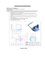
Example: the Falling Smoke Stack<br />
The falling smoke stack is a well-known example where dynamic loads lead to a<br />
structural failure. A falling smoke stack is known to break in two before it hits the<br />
ground because of high tensile stresses caused by a bending moment during the fall.<br />
Figure 6-16 shows a simple representation of the falling smoke stack in <strong>Working</strong><br />
<strong>Model</strong>.<br />
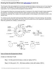
In Figure 6-17, we show both the static and dynamic analyses of this event. In the<br />
static beam analysis, the beam is rigidly attached to the background. In the dynamic<br />
analysis, the connection is made with a circular pin, which allows the beam to rotate.<br />
Figure 6-17 shows that the difference between the two analyses is substantial. Figure<br />
6-17 also highlights that in the dynamic analysis, the peak bending moment occurs in<br />
the middle of the beam which is consistent with the notion that a falling smoke stack<br />
breaks into two pieces before hitting the ground.
WM52ProductGuide.fm Page 25 Tuesday, March 2, 2004 12:04 PM<br />
Figure 6-17<br />
Analysis of Static and Dynamic<br />
Beams<br />
6.3 The Optimize Script<br />
6. Scripts 25<br />
This script will adjust a user-specified parameter to minimize a user-specified cost.<br />
When invoked, choose the "Optimization Demo" option to see some example uses for<br />
this script.<br />
The script needs:<br />
Static Beam<br />
Dynamic Beam<br />
• An input parameter to vary, named "P0".<br />
• A meter named “COST” that measures the cost function to minimize.<br />
To inform <strong>Working</strong> <strong>Model</strong> of the length of your simulation run, add a pause control.<br />
If you need to stop the optimization at any time, use Ctrl-C.<br />
6.4 The Create Constraint Script<br />
Create Constraint allows you to create constraints between points. The type of<br />
constraint that you can create depends on the number of points selected:<br />
A. One point (Force, Torque)
WM52ProductGuide.fm Page 26 Tuesday, March 2, 2004 12:04 PM<br />
26<br />
B. Two Points (Actuator, Damper, Pin, Rod, Rope, Separator, Spring, Spring/<br />
Damper)<br />
C. Three or more points (Pin)<br />
Create and/or select the point(s) where you would like to add a constraint. Run the<br />
script and specify the desired constraint.<br />
6.5 The Document <strong>Model</strong> Script<br />
This script enables you to completely document a model. Running this script produces<br />
a text file that lists information (e.g., units, properties, bodies, constraints, integration<br />
settings, etc.) that describes the model.<br />
6.6 The Zoom to Extent Script<br />
Zoom to Extent adjusts the zoom so you can view your entire model in the simulation<br />
window. Simply select this script from the menu to run it.<br />
6.7 The Measure Between Points Script<br />
Running this script creates a meter that measures the distance between the two selected<br />
points. The distance is displayed once you run (or re-run) your model.<br />
6.8 The Flip Polygon Script<br />
Flip Polygon allows you to flip a polygon into a mirror-image position. Before<br />
running this script, create and select a polygon. Run the script, then specify whether<br />
you want to flip the polygon horizontally or vertically.<br />
6.9 The Pin Friction Script<br />
This script allows you to simulate friction on pin joints. Before running the script,<br />
create and select a pin joint. Run the script to create two input controls: one for the<br />
effective pin radius and the other for the coefficient of friction in the joint. Adjust the<br />
values and run your model to simulate the friction.
WM52ProductGuide.fm Page 27 Tuesday, March 2, 2004 12:04 PM<br />
7. Technical Support and Other Services 27<br />
6.10 The Slot Friction Script<br />
The Slot Friction script allows you to model friction in your slot joints. Before<br />
running the script, create and select a slot joint. Run the script to create the applied<br />
forces that are programmed to model friction in the slot. An input control is created<br />
for you to assign the friction coefficient.<br />
6.11 The Slot Damping Script<br />
The Slot Damping script allows you to model damping in your slot joints. Before<br />
running the script, create and select a slot joint. Run the script to create the applied<br />
forces that are programmed to model damping in the slot. An input control is created<br />
for you to assign the damping coefficient. The units for the damping coefficient are<br />
consistent with those currently assigned to your simulation. For example, if you<br />
currently have selected force to be represented in lbf and velocity in feet/second, then<br />
the damping coefficient has units of lbf-second/foot.<br />
7. Technical Support and Other Services<br />
7.1 Technical Support<br />
Technical support for the use of <strong>Working</strong> <strong>Model</strong> is provided by <strong>Working</strong> <strong>Model</strong><br />
agents, authorized dealers, and MSC.Software. Support for cducational customers is<br />
restricted to the first four months of ownership, and is limited to questions on<br />
installation and basic operations.<br />
If you purchased <strong>Working</strong> <strong>Model</strong> through a reseller, contact the reseller directly for<br />
technical support.<br />
If you purchased <strong>Working</strong> <strong>Model</strong> through MSC.Software, contact MSC.Software for<br />
technical support:<br />
• E-mail: wm.support@mscsoftware.com<br />
• Fax: (650) 574-7541, Attention: <strong>Working</strong> <strong>Model</strong> 2D Support.<br />
• Phone: (800) 732-7284, M-F 7 AM to 3 PM Pacific Standard Time.
WM52ProductGuide.fm Page 28 Tuesday, March 2, 2004 12:04 PM<br />
28<br />
7.2 Contacting Technical Support<br />
Before contacting your technical support provider, please refer first to the Index, Table<br />
of Contents, and Appendix C in the <strong>Working</strong> <strong>Model</strong> User’s Manual. If you cannot find<br />
the answer to your question, please make sure to have the following information when<br />
contacting us or your sales agent:<br />
• Serial number of the product<br />
• Product name (e.g., <strong>Working</strong> <strong>Model</strong> version 5.2)<br />
• Operating system and version (e.g., Windows 95)<br />
• Hardware configuration (RAM and free hard disk space)<br />
• Specific descriptions of the problem and a way to reproduce it<br />
7.3 Consulting Services<br />
MSC.Software and its authorized dealers and agents provide consulting services on<br />
the construction, modeling, and analysis of mechanical systems using <strong>Working</strong><br />
<strong>Model</strong>. For more information, call MSC.Software at (650) 574-7777.<br />
7.4 World Wide Web<br />
http://www.workingmodel.com/<br />
The website features free demo files, technical notes, and periodic updates to the<br />
product. Also, please check the FAQ page of our website for answers to frequently<br />
asked questions.<br />
8. Troubleshooting and Helpful<br />
Suggestions<br />
8.1 <strong>Working</strong> <strong>Model</strong> Cannot Find Hardware Key<br />
Several issues can contribute to this error message.<br />
• If you have a Compaq Deskpro or Presario, and you are running Windows 95,<br />
the parallel ports are often hard-wired into “ECP Mode”. Currently, the hardware<br />
key does not support ECP Mode (Rainbow is working on drivers which<br />
allow ECP Mode, but at present time have given no release date.). In order to<br />
fix this problem, you must change the configuration of your computer via a<br />
jumper cable to Standard Mode. Please consult your computer owner’s manual.
WM52ProductGuide.fm Page 29 Tuesday, March 2, 2004 12:04 PM<br />
9. Limitations 29<br />
Note: printer drivers that require ECP Mode will still work properly because the<br />
software is capable of switching the parallel port into ECP Mode.<br />
• If you are running <strong>Working</strong> <strong>Model</strong> with a stand-alone license, make sure you<br />
either have a hardware key attached to the parallel port (see “Attaching the<br />
Hardware Key (Professional Product)”). If you have concurrent network<br />
licenses, make sure the NetSentinel server is running (see “Installing and Running<br />
the NetSentinel Server”) and all the network functions are operational.<br />
• You may be running <strong>Working</strong> <strong>Model</strong> over the network and failed to install the<br />
appropriate hardware key driver on the local machine. See “Attaching the<br />
Hardware Key (Professional Product)” for more information.<br />
• If you have multiple parallel ports, try attaching the hardware key on a different<br />
port.<br />
• All the available network licenses for <strong>Working</strong> <strong>Model</strong> may be in use. Either<br />
wait for other users to exit <strong>Working</strong> <strong>Model</strong>, or contact MSC.Software to purchase<br />
more licenses.<br />
• If all else fails, restart your computer and try again.<br />
8.2 Simulation Generates Jaggy Plots<br />
Decrease the Positional Error and/or Animation Step (in Accuracy dialog) to increase<br />
accuracy.<br />
8.3 My AVI Export Does Not Work Well for RLE<br />
Compression (Windows only)<br />
Some systems may experience problems while exporting Video for Windows files<br />
from Interactive Physics with the RLE compression mode. Try using another<br />
compression mode, such as Microsoft ® Video 1.<br />
9. Limitations<br />
This section provides addenda to the documentation and known problems and<br />
incompatibilities.<br />
9.1 <strong>Working</strong> <strong>Model</strong> Basic<br />
<strong>Working</strong> <strong>Model</strong> Basic featured in <strong>Working</strong> <strong>Model</strong> 4.0 and 5.0 is slightly different<br />
from the previous version. If you encounter a script that ceases to compile or run<br />
under version 4.0 or 5.0, please refer to the following information.
WM52ProductGuide.fm Page 30 Tuesday, March 2, 2004 12:04 PM<br />
30<br />
AppFileName<br />
The function AppFileName is no longer supported.<br />
Save As Binary<br />
The “Save As Binary” functionality, supported under the Script Editor with<br />
<strong>Working</strong> <strong>Model</strong> 3.0, is no longer supported. Scripts saved as binary under version 3.0<br />
are incompatible with version 4.0. Run all scripts as text.<br />
Double Precision<br />
<strong>Working</strong> <strong>Model</strong> 3.0 left unchecked small, fractional errors accumulated in double<br />
precision numbers. Therefore, the following script:<br />
Sub Main()<br />
end sub<br />
dim i as double<br />
for i = 0.5 to 1.0 step 0.1<br />
Msgbox i<br />
next<br />
ran up to “1.0” in version 3.0. In <strong>Working</strong> <strong>Model</strong> 4.0, the loop terminates after<br />
showing the value “0.9”. This new behavior is consistent with Microsoft<br />
Visual Basic ® .<br />
9.2 Curved Bodies<br />
For curved bodies, the snap points are available only at the frame of reference (FOR).<br />
However, you can find the snap points on a curved body by temporarily turning off the<br />
“Curved Body” checkbox in the Geometry window.<br />
The boundary of a curved body may appear “jaggy” when you zoom in, because<br />
<strong>Working</strong> <strong>Model</strong> approximates the splined boundary with linear segments for<br />
rendering purposes only. The simulation engine, on the other hand, treats each curved<br />
body’s boundary as a true NURB representation.<br />
9.3 Double Clicking on a .WM File Launches<br />
Windows Media Player<br />
<strong>Working</strong> <strong>Model</strong> files and Windows Media Player files share the same “.wm”<br />
file extension. Double-clicking on a file that has a “.wm” file extension<br />
prompts the Operating System to open the selected file with the default<br />
application, which is usually the Windows Media Player. To open <strong>Working</strong>
WM52ProductGuide.fm Page 31 Tuesday, March 2, 2004 12:04 PM<br />
9. Limitations 31<br />
<strong>Model</strong> files with the “.wm” file extension you should launch the <strong>Working</strong><br />
<strong>Model</strong> 2D 5.0 application and then use the File->Open command. Newer<br />
versions of <strong>Working</strong> <strong>Model</strong> will use the “.wm2” file extension.<br />
9.4 Dynamic Data Exchange (Windows Only)<br />
The filename of a Microsoft Excel file needs to match 8.3 format. This limitation does<br />
not apply to the directory path. For example, the pathname:<br />
C:\my folder\data files\project1.xls<br />
is acceptable, whereas:<br />
C:\my folder\data files\My_Project.xls<br />
is unacceptable, because the filename does not match the 8.3 format.<br />
9.5 Apple Guide Conflicts (Macintosh only)<br />
There is also an interaction between “7.0/7.1 Apple Guide Enabler” and “Dragging<br />
Enabler,” which prevents Apple Guide 2.0 from working properly if “Macintosh Drag<br />
and Drop” is installed by the user. The work-around is to remove “Dragging Enabler”<br />
from your System Extensions Folder. The “7.0/7.1 Apple Guide Enabler” contains the<br />
patches that “Macintosh Drag and Drop” needs to work properly; thus, “Dragging<br />
Enabler” is not needed.<br />
9.6 Degraded Redraw Speed on a Large<br />
Window<br />
You may experience a graphics speed loss if you have a very large document window<br />
(for example, a maximized window on a 1024-by-768 resolution screen). For<br />
optimum performance in playback, resize the window smaller
WM52ProductGuide.fm Page 32 Tuesday, March 2, 2004 12:04 PM<br />
32<br />
10. New Features<br />
10.1 Script Button<br />
<strong>Working</strong> <strong>Model</strong> 2D allows you to create a button that invokes a script written in<br />
<strong>Working</strong> <strong>Model</strong> Basic. The script button serves as a flexible alternative to menu<br />
buttons, since it allows you to invoke a script file that could accomplish far more than<br />
a single menu command. For example, you can create a <strong>Working</strong> <strong>Model</strong> file that<br />
shows several script buttons that guide the user to different simulation scenarios.<br />
To create a script button:<br />
1. Choose Define->New Button->Script Button in the menu.<br />
File open dialog appears.<br />
2. Select the <strong>Working</strong> <strong>Model</strong> Basic script file in the dialog, and click Open.<br />
The script button appears in the <strong>Working</strong> <strong>Model</strong> document, with the file name (minus<br />
the.WBS suffix) as the default button name. You can change the button name in the<br />
Appearance window.<br />
For additional information, see “8.6. Running Scripts” in the <strong>Working</strong> <strong>Model</strong> 2D<br />
User's Manual. For details on <strong>Working</strong> <strong>Model</strong> Basic, see the <strong>Working</strong> <strong>Model</strong> Basic<br />
User's Manual (this can be found on the CD-ROM in<br />
\WM2D\Manuals\WMBasic.pdf).<br />
10.2 Rotating Pictures<br />
Attaching picture images to bodies is discussed in the <strong>Working</strong> <strong>Model</strong> User’s<br />
Manual, “7.6. Pictures,” page 7-27. In Section 7.6, a note indicates that<br />
pictures do not zoom or rotate with the body. <strong>Working</strong> <strong>Model</strong> now allows the<br />
following new functions:<br />
• Pictures attached to bodies may rotate with the body.<br />
• The frame of the picture may be offset and rotated from the frame of the body.<br />
NOTE: The imported picture will not zoom with the body. Therefore, attaching<br />
pictures to bodies is best accomplished by first zooming in or out to a view where the<br />
entire simulation can be seen and then attaching the image to the body.<br />
To create picture objects and attach them to bodies, follow the instructions listed on<br />
page 7-28 of the <strong>Working</strong> <strong>Model</strong> 2D User’s Manual.
WM52ProductGuide.fm Page 33 Tuesday, March 2, 2004 12:04 PM<br />
Figure 10-1<br />
A body and a picture of an<br />
apple, unattached<br />
10. New Features 33<br />
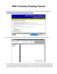
Figure 10-1 of this document shows a polygonal body, a picture of an apple, and a<br />
wedge-shaped platform that is anchored to the ground. After the polygon and the<br />
apple are attached, they translate and rotate together, as shown in Figure 10-2.<br />
In Figure 10-2, the picture is attached to the body using the directions listed in the<br />
<strong>Working</strong> <strong>Model</strong> 2D User’s Manual, page 7-28. The picture is attached to the body so<br />
that the origin and orientation of the picture coincide with those of the body. This is<br />
the default behavior.<br />
Alternatively, the picture can be attached to the body so that it is offset and rotated<br />
away from the body. To offset and rotate the picture from the body:<br />
1. Select the picture (which also selects the body, since the picture is still<br />
attached to the body).<br />
The picture appears selected.<br />
2. Choose Geometry from the Window menu.<br />
The Geometry window appears, as shown in Figure 10-3.<br />
3. Choose Picture from the drop box in the Geometry window.<br />
4. Enter a 1.0 meter and 0.4 radian offset, as shown in Figure 10-3.<br />
5. Run the simulation.
WM52ProductGuide.fm Page 34 Tuesday, March 2, 2004 12:04 PM<br />
34<br />
Figure 10-2<br />
The picture attached to the<br />
body, falling down a wedge<br />
Figure 10-3<br />
Geometry window for the<br />
body and the picture<br />
Because the picture is offset from the body, a gap between the wedge-shaped platform<br />
appears on the first bounce, as shown in Figure 10-4. This offset also causes the<br />
penetration of the picture into the platform on the second bounce.
WM52ProductGuide.fm Page 35 Tuesday, March 2, 2004 12:04 PM<br />
Figure 10-4<br />
The attached picture with a<br />
1.0m and 0.4 radian offset<br />
Figure 10-5<br />
A body and picture,<br />
unattached, with a cyan<br />
background<br />
10. New Features 35<br />
10.3 Transparent or Non-Rectangular Pictures<br />
In Figure 10-2 and Figure 10-4, the picture includes the white, rectangular boundary<br />
around the apple. The simulation would look better if this boundary were transparent.<br />
To obtain a transparent boundary, color the boundary with cyan (red=0, green=255,<br />
blue=255), as shown in Figure 10-5.
WM52ProductGuide.fm Page 36 Tuesday, March 2, 2004 12:04 PM<br />
36<br />
Figure 10-6<br />
Picture with transparent<br />
background attached to<br />
body<br />
Attach the picture to the body following the steps in the <strong>Working</strong> <strong>Model</strong> User’s<br />
Manual, page 7-28. Notice how the cyan background on the picture becomes<br />
transparent once the picture is attached to the body. The simulation appears in Figure<br />
10-6. Notice that only the apple is seen. The rectangular white background is now<br />
transparent. Compare the visual improvements present in Figure 10-6 to Figure 10-2.<br />
10.4 Showing and Hiding Text Objects<br />
The Appearance window for a Text Object now provides a means for showing the text<br />
only when a certain condition is met. Assuming the “Show” box in the Appearance<br />
window is checked, the Text Object will be shown only when the expression in the<br />
box labeled “Exists when:” evaluates to a non-zero value. Unchecking the “Show”<br />
box will still hide the text permanently, regardless of the expression in the “Exists<br />
when:” box.<br />
Note that entering the constant “0.0” for the expression will not permanently hide the<br />
text unless it is entered as “(0.0)”. This is necessary to create a <strong>Working</strong> <strong>Model</strong><br />
formula out of the constant value of zero.<br />
For more documentation on the Text Object, see “7.5. Text” in the<br />
<strong>Working</strong> <strong>Model</strong> 2D User's Manual.
WM52ProductGuide.fm Page 37 Tuesday, March 2, 2004 12:04 PM<br />
11. Version Comparison<br />
11. Version Comparison 37<br />
Upgrading from version 2.0 to version 5.2<br />
• Improved accuracy of calculations<br />
• Step-by-step introductory demonstration for first-time users<br />
• Vastly improved simulation speed<br />
• Improved interface that is more user-friendly<br />
• Runs on Windows 95, 98, ME, XP, NT, 2000<br />
• RunAllDemoFile script to help you evaluate <strong>Working</strong> <strong>Model</strong><br />
• New and/or enhanced demo files<br />
• DXF import can now import more complex DXF models (i.e., models<br />
with much higher number of points/segments)<br />
• Audio sound has been added to the program<br />
• Sound files (.wav) included<br />
• Streamlined installer<br />
• New picture library with bitmap pictures<br />
• Rotating Pictures: Pictures attached to bodies rotate when the body<br />
rotates.<br />
• Non-Rectangular or Transparent Pictures<br />
• Showing and Hiding of Text Objects: Appearance window for a text<br />
object allows you to show text only when a certain condition is met.<br />
• Slot Friction: Script that allows you to model friction in your slot joints.<br />
• Slot Damping: Script that allows you to model damping in your slot<br />
joints.<br />
• Option to prevent a simulation from running faster than real time<br />
• Showing and hiding text objects<br />
• Available in Homework and Textbook editions<br />
• More ready-to-run simulations in a wider range of physics topics for your<br />
curriculum<br />
• Picture Library<br />
• New Tools:<br />
Curved Polygons<br />
Closed Curved Slot Joints<br />
Square Point element<br />
Slot elements<br />
Curved Slot elements
WM52ProductGuide.fm Page 38 Tuesday, March 2, 2004 12:04 PM<br />
38<br />
Closed Curved Slot elements<br />
Join/Split Command<br />
• Zoom to Extent button<br />
• Script that measures the distance between points<br />
• Create a button that runs any of the scripts under the Script Menu<br />
• Specify overlap error, assembly error, and significant digits<br />
• Better organized two-column palette makes modeling tools more<br />
accessible<br />
• Resize and reshape objects while they are still joined<br />
• External Application Link to software packages such as Excel and<br />
Matlab<br />
• Measure the position, velocity, and acceleration of the center of mass<br />
• Geometry window: specify an object’s geometric properties<br />
• Export simulations to .avi video format for classroom presentations<br />
• Program translated into Japanese<br />
• Japanese user manual, tutorial, and Getting Started Guide are included on<br />
the CD<br />
Upgrading from version 3.0 to version 5.2<br />
• Improved accuracy of calculations<br />
• Runs on Windows 95, 98, ME, XP, NT, 2000<br />
• Step-by-step introductory demonstration for first-time users<br />
• RunAllDemoFile script to help you evaluate <strong>Working</strong> <strong>Model</strong><br />
• New and/or enhanced demo files<br />
• DXF import can now import more complex DXF models (i.e., models<br />
with much higher number of points/segments)<br />
• Audio sound has been added to the program<br />
• Streamlined installer<br />
• New picture library with bitmap pictures<br />
• Zoom to Extent button<br />
• Script Button: Create a button that invokes a script.<br />
• Rotating Pictures: Pictures attached to bodies rotate when the body<br />
rotates.<br />
• Non-Rectangular or Transparent Pictures<br />
• Showing and Hiding of Text Objects: Appearance window for a text<br />
object allows you to show text only when a certain condition is met.
WM52ProductGuide.fm Page 39 Tuesday, March 2, 2004 12:04 PM<br />
11. Version Comparison 39<br />
• Slot Friction: Script that allows you to model friction in your slot joints.<br />
• Slot Damping: Script that allows you to model damping in your slot<br />
joints.<br />
• Program translated into Japanese<br />
• Japanese user manual, tutorial, and Getting Started Guide are included on<br />
the CD<br />
Upgrading from version 5.0 to version 5.2<br />
• Improved accuracy of calculations<br />
• Runs on Windows 95, 98, ME, XP, NT, 2000<br />
• Step-by-step introductory demonstration for first-time users<br />
• RunAllDemoFile script to help you evaluate <strong>Working</strong> <strong>Model</strong><br />
• New and/or enhanced demo files<br />
• DXF import can now import more complex DXF models (i.e., models<br />
with much higher number of points/segments)<br />
• Audio sound has been added to the program<br />
• Streamlined installer<br />
• New picture library with bitmap pictures<br />
• Zoom to Extent button<br />
• Program translated into Japanese<br />
• Japanese user manual, tutorial, and Getting Started Guide are included on<br />
the CD
WM52ProductGuide.fm Page 40 Tuesday, March 2, 2004 12:04 PM<br />
40