MTS/MDA Sensor Board Users Manual
MTS/MDA Sensor Board Users Manual
MTS/MDA Sensor Board Users Manual

You also want an ePaper? Increase the reach of your titles
YUMPU automatically turns print PDFs into web optimized ePapers that Google loves.
<strong>MTS</strong>/<strong>MDA</strong> <strong>Sensor</strong> <strong>Board</strong> User’s <strong>Manual</strong><br />
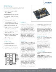
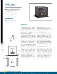
resistance, while in dark conditions, is 520 kΩ. In order to use the light sensor, digital control<br />
signal PW1 must be turned on. The output of the sensor is connected to the analog-digital<br />
converter channel 6 (ADC6, U1 Pin 37). See the circuit below.<br />
R2 Photoresistor<br />
R3, 10 k, 5%<br />
Page 4 Doc. # 7430-0020-05 Rev. A<br />
PW1<br />
Gnd_analog<br />
ADC6<br />
Figure 2-3. Schematic of the light sensor.<br />
Table 2-3. Light <strong>Sensor</strong> Specifications.<br />
Type Clairex CL94L<br />
RON 2 kΩ<br />
ROFF 520 kΩ<br />
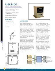
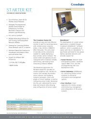
2.4 Prototyping Area<br />
The prototyping area is a series of solder holes and connection points for connecting other<br />
sensors and devices to the Mote. The prototyping area layout is shown in the diagram and tables<br />
below.<br />
Table 2-4. Connection Table for <strong>MTS</strong>101CA. Use the photo (top view) below the table to locate the pins.<br />
a1-a12 No Connect, Bare Hole c1-c12 No Connect, Bare Hole<br />
b1 PW4 (U1-33) b9 I2C_BUS_DATA (U1-22)<br />
b2 PW5 (U1-34) b10 I2C_BUS_CLK (U1-21)<br />
b3 PW6 (U1-35) b11 FLASH_SO (U1-19)<br />
b4 ADC3 (U1-36) b12 FLASH_SI (U1-20)<br />
d1 GND_ANALOG (U1-1) d9 GND (U1-51)<br />
d2 VDD_ANALOG (U1-2) d10 VCC (U1-50)<br />
d3 ADC1 (U1-42) d11 No Connect, Bare Hole<br />
d4 ADC2 (U1-41) d12 No Connect, Bare Hole<br />
e9 PW3 (U1-32) e11 ADC0 (U1-43)<br />
e10 ADC4 (U1-39) e12 GND_ANALOG (U1-1)<br />
a b c d e<br />
a b c d e<br />
1<br />
2<br />
3<br />
4<br />
5<br />
6<br />
7<br />
8<br />
9<br />
10<br />
11<br />
12<br />
Thermistor<br />
Light <strong>Sensor</strong>