MTS/MDA Sensor Board Users Manual
MTS/MDA Sensor Board Users Manual
MTS/MDA Sensor Board Users Manual

You also want an ePaper? Increase the reach of your titles
YUMPU automatically turns print PDFs into web optimized ePapers that Google loves.
<strong>MTS</strong>/<strong>MDA</strong> <strong>Sensor</strong> <strong>Board</strong> User’s <strong>Manual</strong><br />
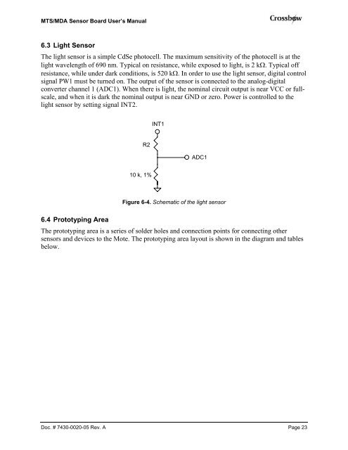
6.3 Light <strong>Sensor</strong><br />
The light sensor is a simple CdSe photocell. The maximum sensitivity of the photocell is at the<br />
light wavelength of 690 nm. Typical on resistance, while exposed to light, is 2 kΩ. Typical off<br />
resistance, while under dark conditions, is 520 kΩ. In order to use the light sensor, digital control<br />
signal PW1 must be turned on. The output of the sensor is connected to the analog-digital<br />
converter channel 1 (ADC1). When there is light, the nominal circuit output is near VCC or fullscale,<br />
and when it is dark the nominal output is near GND or zero. Power is controlled to the<br />
light sensor by setting signal INT2.<br />
R2<br />
10 k, 1%<br />
INT1<br />
ADC1<br />
Figure 6-4. Schematic of the light sensor<br />
6.4 Prototyping Area<br />
The prototyping area is a series of solder holes and connection points for connecting other<br />
sensors and devices to the Mote. The prototyping area layout is shown in the diagram and tables<br />
below.<br />
Doc. # 7430-0020-05 Rev. A Page 23