MTS/MDA Sensor Board Users Manual
MTS/MDA Sensor Board Users Manual
MTS/MDA Sensor Board Users Manual

Create successful ePaper yourself
Turn your PDF publications into a flip-book with our unique Google optimized e-Paper software.
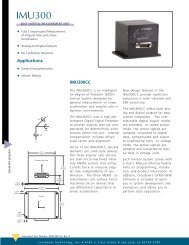
Figure 6-2(b). Schematic of the Thermistor on <strong>MDA</strong>100CB<br />
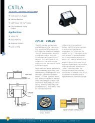
Table 6-2. Resistance vs. Temperature, ADC1 Reading<br />
Temperature<br />
(°C)<br />
Resistance<br />
(Ohms)<br />
<strong>MTS</strong>/<strong>MDA</strong> <strong>Sensor</strong> <strong>Board</strong> User’s <strong>Manual</strong><br />
ADC5 Reading<br />
(% of VCC)<br />
-40 239,800 4%<br />
-20 78,910 11%<br />
0 29,940 25%<br />
25 10,000 50%<br />
40 5592 64%<br />
60 2760 78%<br />
70 1990 83%<br />
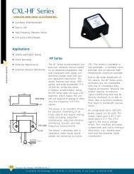
300,000<br />
250,000<br />
200,000<br />
150,000<br />
100,000<br />
50,000<br />
0<br />
Resistance (RT1 Ohms)<br />
-60 -40 -20 0 20 40 60 80 100 120<br />
Temperature (Deg. C)<br />
Figure 6-3. Resistance vs. Temperature Graph<br />
6.2 Conversion to Engineering Units<br />
The Mote’s ADC output can be converted to Kelvin using the following approximation over 0 to<br />
50 °C:<br />
1/T(K) = a + b × ln(Rthr) + c × [ln(Rthr)] 3<br />
where:<br />
Rthr = R1(ADC_FS-ADC)/ADC<br />
a = 0.001010024<br />
b = 0.000242127<br />
c = 0.000000146<br />
R1 = 10 kΩ<br />
ADC_FS = 1023, and<br />
ADC = output value from Mote’s ADC measurement.<br />
Page 22 Doc. # 7430-0020-05 Rev. A