MTS/MDA Sensor Board Users Manual
MTS/MDA Sensor Board Users Manual
MTS/MDA Sensor Board Users Manual

Create successful ePaper yourself
Turn your PDF publications into a flip-book with our unique Google optimized e-Paper software.
<strong>MTS</strong>/<strong>MDA</strong> <strong>Sensor</strong> <strong>Board</strong> User’s <strong>Manual</strong><br />
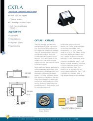
7.1 Theory of Operation<br />
This section briefly describes the operation of the pins available on the <strong>MDA</strong>300CA. A drawing<br />
of the pin-outs and their description is shown in Figure 7-2 below.<br />
Figure 7-2. Pin configuration and assignments of the <strong>MDA</strong>300CA<br />
7.1.1 Single Ended Analog Operation (Channels A0 to A6).<br />
A0 or A11+<br />
Single-ended analog channel 0 or<br />
differential analog channel 11 positive side<br />
Single-ended analog channel 1 or<br />
A1 or A11- differential analog channel 11 negative<br />
side<br />
A2 or A12+<br />
Single-ended analog channel 2 or<br />
differential analog channel 12 positive side<br />
A3 or A12-<br />
Single-ended analog channel 3 or<br />
differential analog channel 12 negative side<br />
A4 or A13+<br />
Single-ended analog channel 4 or<br />
differential analog channel 13 positive side<br />
A5 or A13-<br />
Single-ended analog channel 5 or<br />
differential analog channel 13 negative side<br />
A6 Single-ended analog channel 6<br />
A7+ A7- Differential analog channels 7<br />
A8+ A8- Differential analog channels 8<br />
A9+ A9- Differential analog channels 9<br />
A10+ A10- Differential analog channels 10<br />
DATA I2C Data<br />
CLK I2C Clock<br />
D0 - D6 Digital Lines D0 to D6<br />
C Counter Channel<br />
LED1 RED LED<br />
LED2 GREEN LED<br />
E5.0 5.0 V excitation<br />
E3.3 3.3 V excitation<br />
E2.5 2.5 V excitation<br />
Vcc Vcc of the Mote<br />
RL1 Relay one sides (Normally-Open)<br />
RL2 Relay two sides (Normally-Closed)<br />
NOTE: These channels are shared with differential channels A11–A13 and both of them cannot be<br />
used at the same time.<br />
Signals with dynamic range of 0 to 2.5 V can be plugged to these channels. The least significant<br />
bit value is 0.6 mV. The result of ADC can be converted to voltage knowing that<br />
Voltage = 2.5 × ADC_READING / 4096<br />
Resistors need to be added (soldered) to the <strong>MDA</strong>300CA board to properly scale the voltage<br />
levels of external analog sensors so that the maximum voltage is 2.5 VDC. There are two<br />
scaling-resistors—RA and RB—associated with each ADC channel. These resistors form a simple<br />
two-resistor voltage divider. Therefore, choose values for RA and RB such that the quantity<br />
RB/(RA+RB) multiplied by the maximum output of the sensor is ≤ 2.5 V. The resistors<br />
corresponding to a specific ADC channel are listed in Table 7-2 and the area on the board is<br />
shown in Figure 7-3 below.<br />
Page 26 Doc. # 7430-0020-05 Rev. A