MTS/MDA Sensor Board Users Manual
MTS/MDA Sensor Board Users Manual
MTS/MDA Sensor Board Users Manual

You also want an ePaper? Increase the reach of your titles
YUMPU automatically turns print PDFs into web optimized ePapers that Google loves.
<strong>MTS</strong>/<strong>MDA</strong> <strong>Sensor</strong> <strong>Board</strong> User’s <strong>Manual</strong><br />
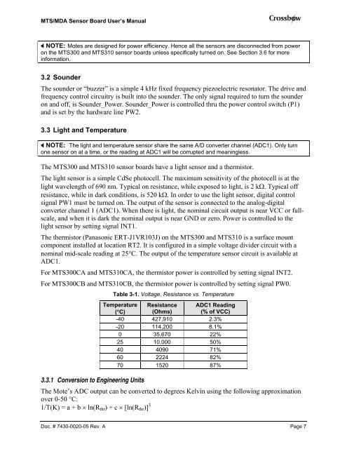
NOTE: Motes are designed for power efficiency. Hence all the sensors are disconnected from power<br />
on the <strong>MTS</strong>300 and <strong>MTS</strong>310 sensor boards unless specifically turned on. See Section 3.6 for more<br />
information.<br />
3.2 Sounder<br />
The sounder or “buzzer” is a simple 4 kHz fixed frequency piezoelectric resonator. The drive and<br />
frequency control circuitry is built into the sounder. The only signal required to turn the sounder<br />
on and off, is Sounder_Power. Sounder_Power is controlled thru the power control switch (P1)<br />
and is set by the hardware line PW2.<br />
3.3 Light and Temperature<br />
NOTE: The light and temperature sensor share the same A/D converter channel (ADC1). Only turn<br />
one sensor on at a time, or the reading at ADC1 will be corrupted and meaningless.<br />
The <strong>MTS</strong>300 and <strong>MTS</strong>310 sensor boards have a light sensor and a thermistor.<br />
The light sensor is a simple CdSe photocell. The maximum sensitivity of the photocell is at the<br />
light wavelength of 690 nm. Typical on resistance, while exposed to light, is 2 kΩ. Typical off<br />
resistance, while in dark conditions, is 520 kΩ. In order to use the light sensor, digital control<br />
signal PW1 must be turned on. The output of the sensor is connected to the analog-digital<br />
converter channel 1 (ADC1). When there is light, the nominal circuit output is near VCC or fullscale,<br />
and when it is dark the nominal output is near GND or zero. Power is controlled to the<br />
light sensor by setting signal INT1.<br />
The thermistor (Panasonic ERT-J1VR103J) on the <strong>MTS</strong>300 and <strong>MTS</strong>310 is a surface mount<br />
component installed at location RT2. It is configured in a simple voltage divider circuit with a<br />
nominal mid-scale reading at 25°C. The output of the temperature sensor circuit is available at<br />
ADC1.<br />
For <strong>MTS</strong>300CA and <strong>MTS</strong>310CA, the thermistor power is controlled by setting signal INT2.<br />
For <strong>MTS</strong>300CB and <strong>MTS</strong>310CB, the thermistor power is controlled by setting signal PW0.<br />
Table 3-1. Voltage, Resistance vs. Temperature<br />
Temperature Resistance ADC1 Reading<br />
(°C) (Ohms)<br />
(% of VCC)<br />
-40 427,910 2.3%<br />
-20 114,200 8.1%<br />
0 35,670 22%<br />
25 10,000 50%<br />
40 4090 71%<br />
60 2224 82%<br />
70 1520 87%<br />
3.3.1 Conversion to Engineering Units<br />
The Mote’s ADC output can be converted to degrees Kelvin using the following approximation<br />
over 0-50 °C:<br />
1/T(K) = a + b × ln(Rthr) + c × [ln(Rthr)] 3<br />
Doc. # 7430-0020-05 Rev. A Page 7