MTS/MDA Sensor Board Users Manual
MTS/MDA Sensor Board Users Manual
MTS/MDA Sensor Board Users Manual

You also want an ePaper? Increase the reach of your titles
YUMPU automatically turns print PDFs into web optimized ePapers that Google loves.
<strong>MTS</strong>/<strong>MDA</strong> <strong>Sensor</strong> <strong>Board</strong> User’s <strong>Manual</strong><br />
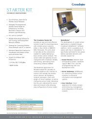
8.1 Theory of Operation<br />
This section briefly describes the operation of the pins available on the <strong>MDA</strong>320CA. A drawing<br />
of the pin-outs and their description is shown in Figure 8-2 below.<br />
PIN CONFIGURATION<br />
A7<br />
A6<br />
E5.0<br />
A5<br />
A4<br />
E2.5<br />
GND<br />
A3<br />
A2<br />
VBAT<br />
GND<br />
A1<br />
A0<br />
GND<br />
E3.3<br />
J5<br />
TOP VIEW<br />
J8<br />
DATA<br />
CLK<br />
LED2<br />
VCC<br />
LED1<br />
GND<br />
D0<br />
D1<br />
D2<br />
D3<br />
D4<br />
D5<br />
D6<br />
D7<br />
C<br />
A7<br />
Single-ended analog channel 7 or<br />
differential analog channel 11 positive side<br />
Single-ended analog channel 6 or<br />
A6 differential analog channel 11 negative<br />
side<br />
E5.0 5.0 V excitation<br />
A5<br />
Single-ended analog channel 5 or<br />
differential analog channel 10 negative side<br />
A4<br />
Single-ended analog channel 4 or<br />
differential analog channel 10 positive side<br />
E2.5 2.5 V excitation<br />
GND Electrical ground<br />
A3<br />
Single-ended analog channel 3 or<br />
differential analog channel 9 negative side<br />
A2<br />
Single-ended analog channel 2 or<br />
differential analog channel 9 positive side<br />
VBAT Voltage of battery on positive terminal<br />
A1<br />
Single-ended analog channel 1 or<br />
differential analog channel 8 negative side<br />
A0<br />
Single-ended analog channel 0 or<br />
differential analog channel 8 positive side<br />
GND Electrical ground<br />
E3.3 3.3 V excitation<br />
DATA I2C Data<br />
CLK I2C Clock<br />
LED2 GREEN LED<br />
Vcc Vcc of the Mote<br />
LED1 RED LED<br />
GND Electrical ground<br />
D0 – D7 Digital Lines D0 to D7<br />
C Counter Channel<br />
Figure 8-2. Pin configuration and assignments of the <strong>MDA</strong>300CA<br />
8.1.1 Single Ended Analog Operation (Channels A0 to A7).<br />
Signals with dynamic range of 0 to 2.5 V can be plugged to these channels. The analog to digital<br />
converter has 16-bit resolution. The least significant bit value is 0.6 mV. The result of ADC can<br />
be converted to voltage knowing that<br />
Voltage = 2.5 × ADC_READING / 65536<br />
Resistors need to be added (soldered) to the <strong>MDA</strong>320CA board to properly scale the voltage<br />
levels of external analog sensors so that the maximum voltage is 2.5 VDC. There are two<br />
scaling-resistors—RA and RB—associated with each ADC channel. These resistors form a simple<br />
two-resistor voltage divider. Therefore, choose values for RA and RB such that the quantity<br />
RB/(RA+RB) multiplied by the maximum output of the sensor is ≤ 2.5 V. The resistors<br />
corresponding to a specific ADC channel are listed in Table 8-2 and the area on the board is<br />
shown in Figure 8-3 below.<br />
Page 30 Doc. # 7430-0020-05 Rev. A