MTS/MDA Sensor Board Users Manual
MTS/MDA Sensor Board Users Manual
MTS/MDA Sensor Board Users Manual

Create successful ePaper yourself
Turn your PDF publications into a flip-book with our unique Google optimized e-Paper software.
<strong>MTS</strong>/<strong>MDA</strong> <strong>Sensor</strong> <strong>Board</strong> User’s <strong>Manual</strong><br />
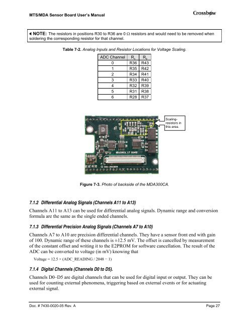
NOTE: The resistors in positions R30 to R36 are 0 Ω resistors and would need to be removed when<br />
soldering the corresponding resistor for that channel.<br />
Table 7-2. Analog Inputs and Resistor Locations for Voltage Scaling.<br />
ADC Channel R A R B<br />
0 R36 R43<br />
1 R35 R42<br />
2 R34 R41<br />
3 R33 R40<br />
4 R32 R39<br />
5 R31 R38<br />
6 R28 R37<br />
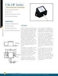
Figure 7-3. Photo of backside of the <strong>MDA</strong>300CA.<br />
7.1.2 Differential Analog Signals (Channels A11 to A13)<br />
Channels A11 to A13 can be used for differential analog signals. Dynamic range and conversion<br />
formula are the same as the single ended channels.<br />
7.1.3 Differential Precision Analog Signals (Channels A7 to A10)<br />
Channels A7 to A10 are precision differential channels. They have a sensor front end with gain<br />
of 100. Dynamic range of these channels is ±12.5 mV. The offset is cancelled by measurement<br />
of the constant offset and writing it to the E2PROM for software cancellation. The result of the<br />
ADC can be converted to voltage (in mV) knowing that<br />
Voltage = 12.5 × (ADC_READING / 2048 − 1)<br />
Scalingresistors<br />
in<br />
this area.<br />
7.1.4 Digital Channels (Channels D0 to D5).<br />
Channels D0–D5 are digital channels that can be used for digital input or output. They can be<br />
used for counting external phenomena, triggering based on external events or for actuating<br />
external signal.<br />
Doc. # 7430-0020-05 Rev. A Page 27