MTS/MDA Sensor Board Users Manual
MTS/MDA Sensor Board Users Manual
MTS/MDA Sensor Board Users Manual

Create successful ePaper yourself
Turn your PDF publications into a flip-book with our unique Google optimized e-Paper software.
<strong>MTS</strong>/<strong>MDA</strong> <strong>Sensor</strong> <strong>Board</strong> User’s <strong>Manual</strong><br />
6 <strong>MDA</strong>100CA/<strong>MDA</strong>100CB<br />
MD100CA and <strong>MDA</strong>100CB have the same content in this chapter except for some minor<br />
changes.<br />
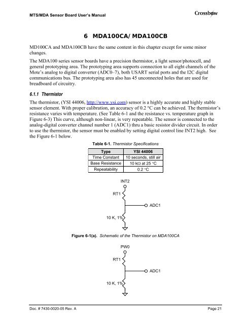
The <strong>MDA</strong>100 series sensor boards have a precision thermistor, a light sensor/photocell, and<br />
general prototyping area. The prototyping area supports connection to all eight channels of the<br />
Mote’s analog to digital converter (ADC0–7), both USART serial ports and the I2C digital<br />
communications bus. The prototyping area also has 45 unconnected holes that are used for<br />
breadboard of circuitry.<br />
6.1.1 Thermistor<br />
The thermistor, (YSI 44006, http://www.ysi.com) sensor is a highly accurate and highly stable<br />
sensor element. With proper calibration, an accuracy of 0.2 °C can be achieved. The thermistor’s<br />
resistance varies with temperature. (See Table 6-1 and the resistance vs. temperature graph in<br />
Figure 6-3) This curve, although non-linear, is very repeatable. The sensor is connected to the<br />
analog-digital converter channel number 1 (ADC1) thru a basic resistor divider circuit. In order<br />
to use the thermistor, the sensor must be enabled by setting digital control line INT2 high. See<br />
the Figure 6-1 below.<br />
Table 6-1. Thermistor Specifications<br />
Type YSI 44006<br />
Time Constant 10 seconds, still air<br />
Base Resistance 10 kΩ at 25 °C<br />
Repeatability 0.2 °C<br />
RT1<br />
10 K, 1%<br />
INT2<br />
ADC1<br />
Figure 6-1(a). Schematic of the Thermistor on <strong>MDA</strong>100CA<br />
RT1<br />
10 K, 1%<br />
PW0<br />
ADC1<br />
Doc. # 7430-0020-05 Rev. A Page 21