Fault Diagnostic System for Cascaded H-Bridge Multilevel Inverter ...
Fault Diagnostic System for Cascaded H-Bridge Multilevel Inverter ...
Fault Diagnostic System for Cascaded H-Bridge Multilevel Inverter ...

You also want an ePaper? Increase the reach of your titles
YUMPU automatically turns print PDFs into web optimized ePapers that Google loves.
Mendes introduced a monitoring technique <strong>for</strong> fault diagnosis in a CID based on Park’<br />
vector approach [17, 18], namely average Park’s vector. Peuget also proposed a fault<br />
detection and isolation on a CID [19], called current-vector trajectory. Basically, Mendes<br />
and Peuget used input motor currents as diagnostic signals and modified the original<br />
Clark and Park trans<strong>for</strong>m method as fault feature extraction to rate input motor current<br />
signals as an important characteristic in order to classify a fault location in an inverter.<br />
The difference between Mendes’s work and Peuget’s work is the diagnostic paradigm to<br />
indicate fault locations (power switch of an inverter).<br />
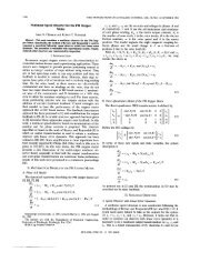
First, Mendes used average current Park’s vector ( Ia,av , Ib,av , and Ic,av ) to detect a fault.<br />
The corresponding Park’s vector can be expressed as follows:<br />
I<br />
I<br />
I<br />
d , av<br />
d , av<br />
q,<br />
av<br />
∠θ<br />
=<br />
=<br />
av<br />
2<br />
3<br />
1<br />
2<br />
= I<br />
I<br />
I<br />
a,<br />
av<br />
a,<br />
av<br />
d , av<br />
−<br />
−<br />
+<br />
28<br />
1<br />
6<br />
1<br />
2<br />
j I<br />
I<br />
q<br />
I<br />
,<br />
b,<br />
av<br />
c,<br />
av<br />
.<br />
−<br />
1<br />
6<br />
I<br />
c,<br />
av<br />
,<br />
(2.6)<br />
The input motor currents are average value over one period. The magnitude and phase<br />
angle of the average vector (Id,av , Iq,av) can be calculated in the complex coordinate.<br />
Obviously, the average current vector in orthogonal space runs in a circuit will be zero<br />
<strong>for</strong> a normal condition of a CID. In contrast, the magnitude of the vector will not be zero<br />
if a fault occurs; normally, the magnitude will exceed some threshold value. The average<br />
phase angle can be used to identify a fault location. Trajectories of Park’s vector<br />
corresponding with the inverter switch locations (Figure 2.3) are illustrated in Figure 2.5.