Fault Diagnostic System for Cascaded H-Bridge Multilevel Inverter ...
Fault Diagnostic System for Cascaded H-Bridge Multilevel Inverter ...
Fault Diagnostic System for Cascaded H-Bridge Multilevel Inverter ...

You also want an ePaper? Increase the reach of your titles
YUMPU automatically turns print PDFs into web optimized ePapers that Google loves.
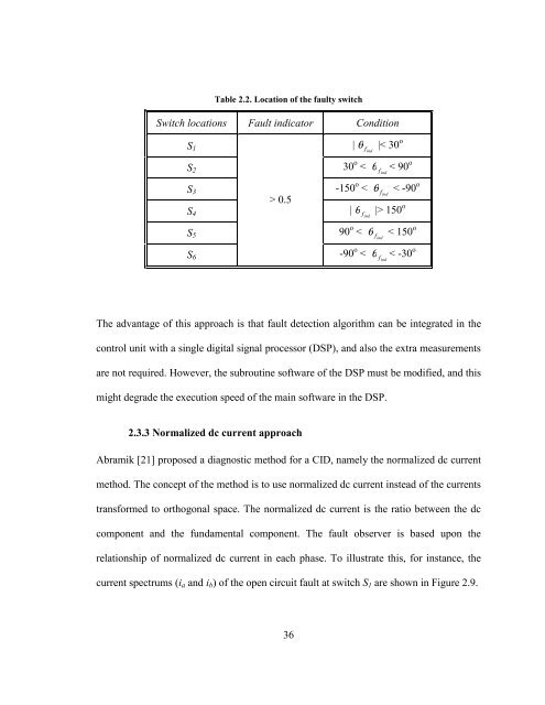
Table 2.2. Location of the faulty switch<br />
Switch locations <strong>Fault</strong> indicator Condition<br />
S1 | θ f |< 30 ind<br />
o<br />
S2 30 o < θ f < 90 ind<br />
o<br />
S3 -150 o < θ f < -90 ind<br />
o<br />
S4 | find<br />
36<br />
θ |> 150 o<br />
S5 90 o < θ f < 150 ind<br />
o<br />
S6<br />
> 0.5<br />
-90 o < θ f < -30 ind<br />
o<br />
The advantage of this approach is that fault detection algorithm can be integrated in the<br />
control unit with a single digital signal processor (DSP), and also the extra measurements<br />
are not required. However, the subroutine software of the DSP must be modified, and this<br />
might degrade the execution speed of the main software in the DSP.<br />
2.3.3 Normalized dc current approach<br />
Abramik [21] proposed a diagnostic method <strong>for</strong> a CID, namely the normalized dc current<br />
method. The concept of the method is to use normalized dc current instead of the currents<br />
trans<strong>for</strong>med to orthogonal space. The normalized dc current is the ratio between the dc<br />
component and the fundamental component. The fault observer is based upon the<br />
relationship of normalized dc current in each phase. To illustrate this, <strong>for</strong> instance, the<br />
current spectrums (ia and ib) of the open circuit fault at switch S1 are shown in Figure 2.9.