Fault Diagnostic System for Cascaded H-Bridge Multilevel Inverter ...
Fault Diagnostic System for Cascaded H-Bridge Multilevel Inverter ...
Fault Diagnostic System for Cascaded H-Bridge Multilevel Inverter ...

You also want an ePaper? Increase the reach of your titles
YUMPU automatically turns print PDFs into web optimized ePapers that Google loves.
Current (A)<br />
30<br />
20<br />
10<br />
0<br />
-10<br />
-20<br />
Ic Ib<br />
Ia<br />
-30<br />
0 50 100 150 200 250 300 350 400 450<br />
Sampling points<br />
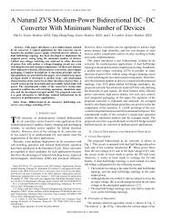
Figure 2.8. Line currents during open circuit faults at S1.<br />
Figure 2.8 shows the plot of line currents during open circuit at switch S1. Obviously, the<br />
currents in orthogonal space are related with the switch locations as shown in Figure 2.7.<br />
The several locus curves at the same plot of each current trajectory are the current cycles<br />
of the motor. Obviously, slope detection and Park’s average vector method may have a<br />
problem to detect the faults when the CID is running at light load or at low modulation<br />
index. As represented in Figure 2.7, the vector angle in orthogonal space is dependent<br />
with the load currents; <strong>for</strong> instance, if the fault occurs at S6 during light load operation,<br />
the vector angle of S3 and S6 is located at the same interval as depicted in Figure 2.7 (d)<br />
and (f). Also, the switch S3 and S6 are placed in different inverter legs so that the<br />
detection system using slope detection and Park’s average vector method would be<br />
incorrectly detected.<br />
34